Page 1551 of 1690
H42657
H42659
60±14
±
SUPPLEMENTAL RESTRAINT SYSTEM SUPPLEMENTAL RESTRAINT SYSTEM
AVENSIS REPAIR MANUAL (RM1018E)
10. INSTRUMENT PANEL AIRBAG ASSY (VEHICLE IN- VOLVED IN COLLISION AND AIRBAG IS NOT
DEPLOYED)
(a)Do a diagnostic system check (See page 05±1184).
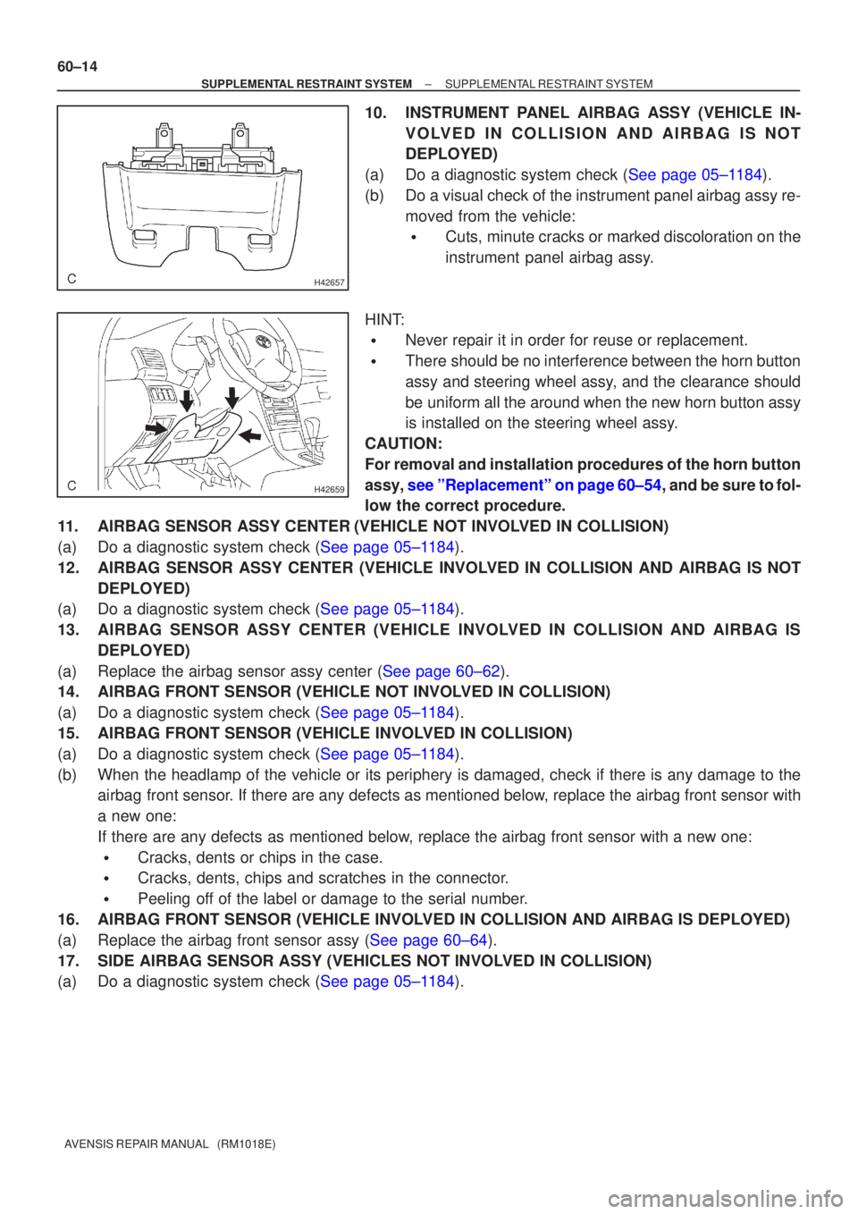
(b) Do a visual check of the instrument panel airbag assy re- moved from the vehicle:
�Cuts, minute cracks or marked discoloration on the
instrument panel airbag assy.
HINT:
�Never repair it in order for reuse or replacement.
�There should be no interference between the horn button
assy and steering wheel assy, and the clearance should
be uniform all the around when the new horn button assy
is installed on the steering wheel assy.
CAUTION:
For removal and installation procedures of the horn button
assy, see ºReplacementº on page 60±54, and be sure to fol-
low the correct procedure.
11. AIRBAG SENSOR ASSY CENTER (VEHICLE NOT INVOLVED IN COLLISION)
(a)Do a diagnostic system check (See page 05±1184).
12. AIRBAG SENSOR ASSY CENTER (VEHICLE INVOLVED IN COLLISION AND AIRBAG IS NOT DEPLOYED)
(a)Do a diagnostic system check (See page 05±1184).
13. AIRBAG SENSOR ASSY CENTER (VEHICLE INVOLVED IN COLLISION AND AIRBAG IS
DEPLOYED)
(a)Replace the airbag sensor assy center (See page 60±62).
14. AIRBAG FRONT SENSOR (VEHICLE NOT INVOLVED IN COLLISION)
(a)Do a diagnostic system check (See page 05±1184).
15. AIRBAG FRONT SENSOR (VEHICLE INVOLVED IN COLLISION)
(a)Do a diagnostic system check (See page 05±1184).
(b) When the headlamp of the vehicle or its periphery is damaged, check if t\
here is any damage to the airbag front sensor. If there are any defects as mentioned below, replace the airbag front sensor with
a new one:
If there are any defects as mentioned below, replace the airbag front sensor with a new one:
�Cracks, dents or chips in the case.
�Cracks, dents, chips and scratches in the connector.
�Peeling off of the label or damage to the serial number.
16. AIRBAG FRONT SENSOR (VEHICLE INVOLVED IN COLLISION AND AIRBAG IS DEPLOYED)
(a)Replace the airbag front sensor assy (See page 60±64).
17. SIDE AIRBAG SENSOR ASSY (VEHICLES NOT INVOLVED IN COLLISION)
(a)Do a diagnostic system check (See page 05±1184).
Page 1590 of 1690
80027±04
F44171
±
VEHICLE CONTROL SYSTEM IGNITION OR STARTER SWITCH ASSY
80±1
AVENSIS REPAIR MANUAL (RM1018E)
IGNITION OR STARTER SWITCH ASSY
REPLACEMENT
HINT:
The installation is in the reverse order of the removal.
1.REMOVE STEERING COLUMN COVER LWR (See page 50±9)
2.REMOVE STEERING COLUMN COVER UPR (See page 50±9)
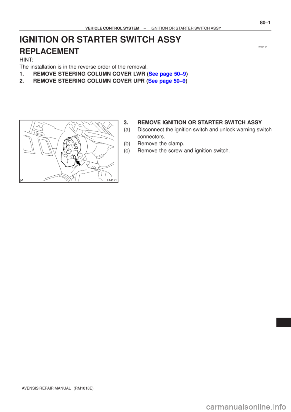
3. REMOVE IGNITION OR STARTER SWITCH ASSY
(a) Disconnect the ignition switch and unlock warning switchconnectors.
(b) Remove the clamp.
(c) Remove the screw and ignition switch.
Page 1670 of 1690
660CR±01
I35801:Claw
66±24
±
WIPER & WASHER WINDSHIELD WIPER SWITCH ASSY
AVENSIS REPAIR MANUAL (RM1018E)
WINDSHIELD WIPER SWITCH ASSY
REPLACEMENT
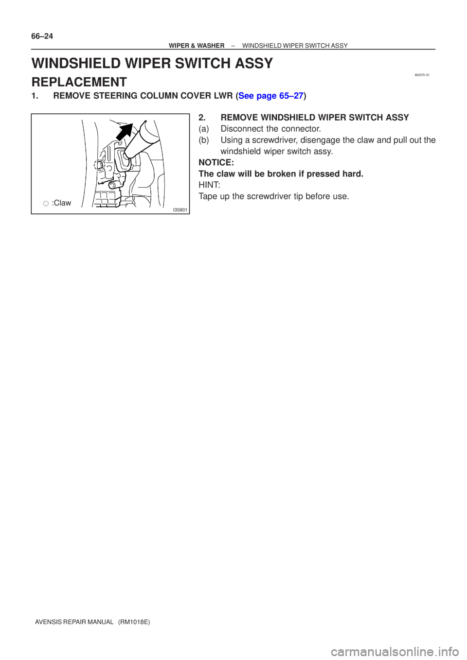
1.REMOVE STEERING COLUMN COVER LWR (See page 65±27) 2. REMOVE WINDSHIELD WIPER SWITCH ASSY
(a) Disconnect the connector.
(b) Using a screwdriver, disengage the claw and pull out thewindshield wiper switch assy.
NOTICE:
The claw will be broken if pressed hard.
HINT:
Tape up the screwdriver tip before use.
Page 1678 of 1690
E67353
A
B
C
D
Rain Sensor Adjust Switch
E34081
66±8
± WIPER & WASHERWIPER AND WASHER SYSTEM
AVENSIS REPAIR MANUAL (RM1018E)
Rear Washer Switch (w/ Rear Wiper)
Switch positionTester conditionSpecified condition
OFF±No continuity
ON (Rear wiper switch
OFF position side)2 (EW) ± 3 (WR)Continuity
ON (Rear wiper switch
ON position side)2 (EW) ± 3 (WR),
2 (EW) ± 10 (+1R)Continuity
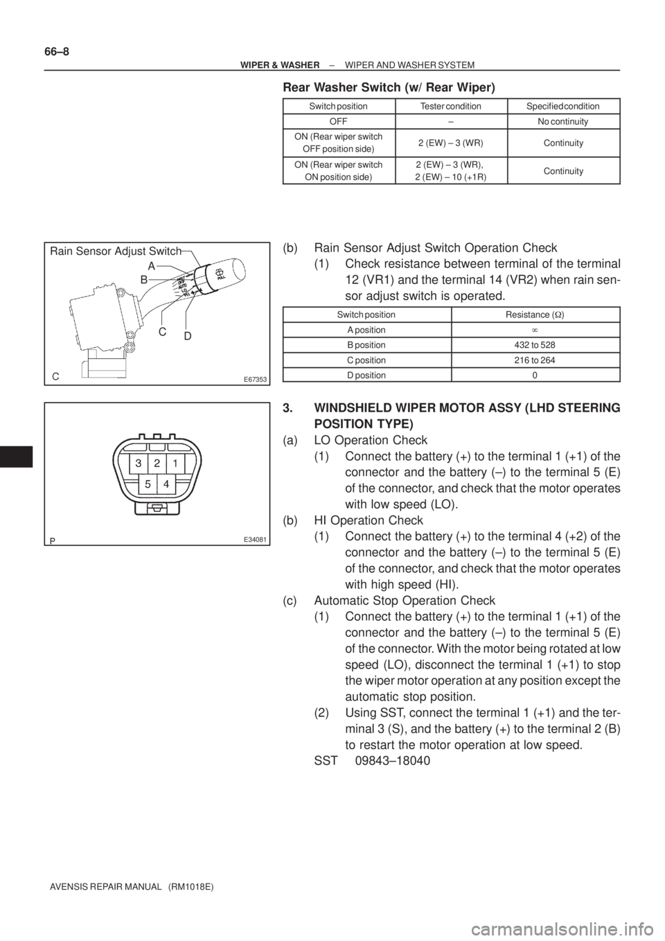
(b) Rain Sensor Adjust Switch Operation Check
(1) Check resistance between terminal of the terminal
12 (VR1) and the terminal 14 (VR2) when rain sen-
sor adjust switch is operated.
Switch positionResistance (�)
A position�
B position432 to 528
C position216 to 264
D position0
3. WINDSHIELD WIPER MOTOR ASSY (LHD STEERING
POSITION TYPE)
(a) LO Operation Check
(1) Connect the battery (+) to the terminal 1 (+1) of the
connector and the battery (±) to the terminal 5 (E)
of the connector, and check that the motor operates
with low speed (LO).
(b) HI Operation Check
(1) Connect the battery (+) to the terminal 4 (+2) of the
connector and the battery (±) to the terminal 5 (E)
of the connector, and check that the motor operates
with high speed (HI).
(c) Automatic Stop Operation Check
(1) Connect the battery (+) to the terminal 1 (+1) of the
connector and the battery (±) to the terminal 5 (E)
of the connector. With the motor being rotated at low
speed (LO), disconnect the terminal 1 (+1) to stop
the wiper motor operation at any position except the
automatic stop position.
(2) Using SST, connect the terminal 1 (+1) and the ter-
minal 3 (S), and the battery (+) to the terminal 2 (B)
to restart the motor operation at low speed.
SST 09843±18040
Page 1679 of 1690
E65740Automatic Stop Position
E34081
E67354
Automatic Stop Position 9�+5�
±10�
± WIPER & WASHERWIPER AND WASHER SYSTEM
66±9
AVENSIS REPAIR MANUAL (RM1018E)
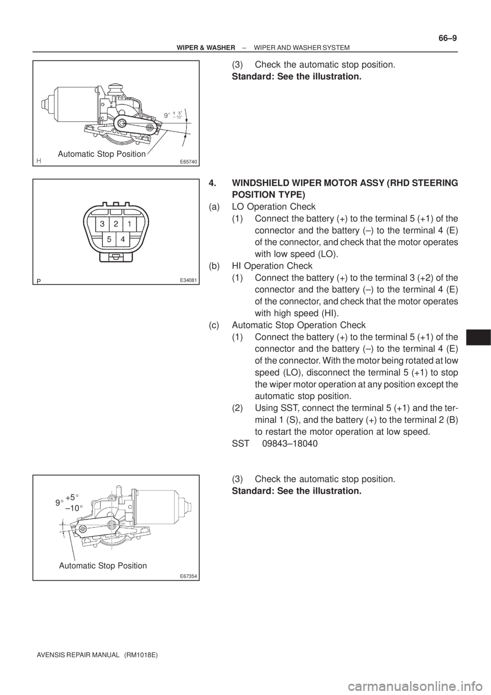
(3) Check the automatic stop position.
Standard: See the illustration.
4. WINDSHIELD WIPER MOTOR ASSY (RHD STEERING
POSITION TYPE)
(a) LO Operation Check
(1) Connect the battery (+) to the terminal 5 (+1) of the
connector and the battery (±) to the terminal 4 (E)
of the connector, and check that the motor operates
with low speed (LO).
(b) HI Operation Check
(1) Connect the battery (+) to the terminal 3 (+2) of the
connector and the battery (±) to the terminal 4 (E)
of the connector, and check that the motor operates
with high speed (HI).
(c) Automatic Stop Operation Check
(1) Connect the battery (+) to the terminal 5 (+1) of the
connector and the battery (±) to the terminal 4 (E)
of the connector. With the motor being rotated at low
speed (LO), disconnect the terminal 5 (+1) to stop
the wiper motor operation at any position except the
automatic stop position.
(2) Using SST, connect the terminal 5 (+1) and the ter-
minal 1 (S), and the battery (+) to the terminal 2 (B)
to restart the motor operation at low speed.
SST 09843±18040
(3) Check the automatic stop position.
Standard: See the illustration.