Page 70 of 1690
320GA±03
G23177
Disc Brake
Cylinder Assy LH� GasketFlexible Hose
Disc Brake
Pad Kit Front
Front Disc Brake
Pad Support Plate No.1
Front Disc Brake
Cylinder Slide Pin (No.2)
Front Disc Brake
Bush Dust Boot Front Disc Brake
Cylinder Slide Pin (No.1)
Front Disc Brake
Cylinder Slide Bush
Front Disc Brake
Cylinder Mounting LH
� Cylinder Boot � Piston Seal
Front Disc
Brake PistonFront Disc
30 (306, 22)
102 (1,040, 75)
30 (306, 22)
Bleeder Plug CapFront Disc Brake
Bleeder Plug
� Non±reusable part
N�m (kgf�cm, ft�lbf) : Specified torque
Lithium soap base glycol grease
29 (296, 21)
10 (102, 7)
Union bolt
Front Disc Brake
Pad Support Plate No.2
102 (1,040, 75)
�Front Disc Brake
Bush Dust Boot � Bolt
� Bolt
�
�
32±40
± BRAKEFRONT BRAKE
AVENSIS REPAIR MANUAL (RM1018E)
FRONT BRAKE
COMPONENTS
Page 72 of 1690
F45420
Front Disc Brake Cylinder Mounting
Bush Dust Boot
F45418
C64095
G23222
G23223
32±42
± BRAKEFRONT BRAKE
AVENSIS REPAIR MANUAL (RM1018E)
6. REMOVE FRONT DISC BRAKE BUSH DUST BOOT
(a) Remove the 2 front disc brake bush dust boots from the
front disc brake cylinder mounting LH.
7. REMOVE FRONT DISC BRAKE CYLINDER
MOUNTING LH
(a) Remove the 2 bolts and front disc brake cylinder mount-
ing LH.
8. REMOVE FRONT DISC BRAKE PISTON
(a) Place a shop rug between the front disc brake piston and
the disc brake cylinder assy LH.
(b) Use compressed air to remove the front disc brake piston
from the disc brake cylinder assy LH.
CAUTION:
Do not place your fingers in front of the piston when using
compressed air.
NOTICE:
Do not spatter the brake fluid.
9. REMOVE CYLINDER BOOT
(a) Using a screwdriver, remove the cylinder boot.
10. REMOVE PISTON SEAL
(a) Using a screwdriver, remove the piston seal.
NOTICE:
Do not damage the inner cylinder and cylinder groove.
Page 74 of 1690

G23226Lithium soap base glycol grease
Cylinder Boot
Piston
G23225
Cylinder Boot
Piston
F45418
F45420
Front Disc Brake Cylinder Mounting
Bush Dust Boot
Lithium soap base glycol grease
32±44
± BRAKEFRONT BRAKE
AVENSIS REPAIR MANUAL (RM1018E)
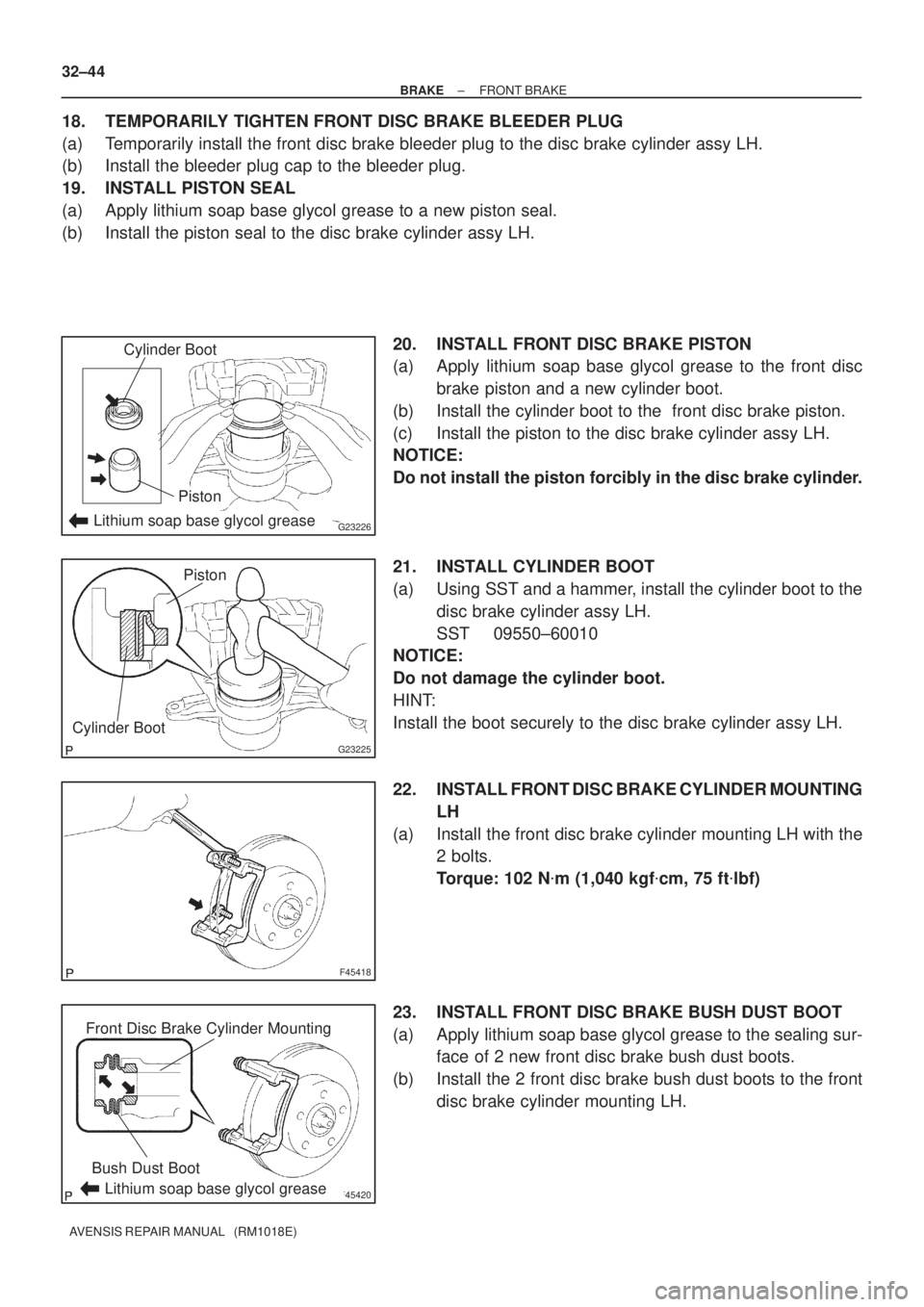
18. TEMPORARILY TIGHTEN FRONT DISC BRAKE BLEEDER PLUG
(a) Temporarily install the front disc brake bleeder plug to the disc brake cylinder assy LH.
(b) Install the bleeder plug cap to the bleeder plug.
19. INSTALL PISTON SEAL
(a) Apply lithium soap base glycol grease to a new piston seal.
(b) Install the piston seal to the disc brake cylinder assy LH.
20. INSTALL FRONT DISC BRAKE PISTON
(a) Apply lithium soap base glycol grease to the front disc
brake piston and a new cylinder boot.
(b) Install the cylinder boot to the front disc brake piston.
(c) Install the piston to the disc brake cylinder assy LH.
NOTICE:
Do not install the piston forcibly in the disc brake cylinder.
21. INSTALL CYLINDER BOOT
(a) Using SST and a hammer, install the cylinder boot to the
disc brake cylinder assy LH.
SST 09550±60010
NOTICE:
Do not damage the cylinder boot.
HINT:
Install the boot securely to the disc brake cylinder assy LH.
22. INSTALL FRONT DISC BRAKE CYLINDER MOUNTING
LH
(a) Install the front disc brake cylinder mounting LH with the
2 bolts.
Torque: 102 N�m (1,040 kgf�cm, 75 ft�lbf)
23. INSTALL FRONT DISC BRAKE BUSH DUST BOOT
(a) Apply lithium soap base glycol grease to the sealing sur-
face of 2 new front disc brake bush dust boots.
(b) Install the 2 front disc brake bush dust boots to the front
disc brake cylinder mounting LH.
Page 76 of 1690
320GE±03
G23180
� Gasket Flexible Hose
30 (306, 22)
Disc Brake Cylinder
Assy Rear LH
Disc Brake
Pad Kit Rear
� Non±reusable part
N�m (kgf�cm, ft�lbf) : Specified torque
Lithium soap base glycol grease
Rear Disc Brake
Bush Dust Boot
Rear Disc Brake
Pad Support Plate No.1
Rear Disc Brake
Cylinder Mounting LH
RearDisc
Brake Piston
Cylinder Boot � Piston Seal
Rear Disc Brake
Cylinder Slide Pin (No.2) Bleeder Plug Cap
Rear Disc Brake
Bleeder Plug
Rear Disc Brake
Cylinder Slide Bush
Rear Disc Brake
Cylinder Slide Pin (No.1)
Rear Disc Brake
Bush Dust Boot Rear Disc
Parking Brake Shoe
Adjusting Hole Plug
47 (475, 34)
30 (306, 22)
47 (475, 34)
29 (296, 21)
10 (102, 7)
Rear Disc Brake
Pad Support Plate No.2
Union Bolt
�� � Bolt � Bolt
32±46
± BRAKEREAR BRAKE
AVENSIS REPAIR MANUAL (RM1018E)
REAR DISC BRAKE
COMPONENTS
Page 78 of 1690
F45439
Front Disc Brake Cylinder Mounting
Bush Dust Boot
F45704
F42270
G23222
G23223
32±48
± BRAKEREAR BRAKE
AVENSIS REPAIR MANUAL (RM1018E)
6. REMOVE REAR DISC BRAKE BUSH DUST BOOT
(a) Remove the 2 rear disc brake bush dust boots from the
rear disc brake cylinder mounting LH.
7. REMOVE REAR DISC BRAKE CYLINDER MOUNTING
LH
(a) Remove the 2 bolts and rear disc brake cylinder mounting
LH.
8. REMOVE REAR DISC BRAKE PISTON
(a) Place a shop rug between the rear disc brake piston and
the disc brake cylinder assy rear LH.
(b) Use compressed air to remove the rear disc brake piston
from the disc brake cylinder assy rear LH.
CAUTION:
Do not place your fingers in front of the piston when using
compressed air.
NOTICE:
Do not spatter the brake fluid.
9. REMOVE CYLINDER BOOT
(a) Using a screwdriver, remove the cylinder boot.
10. REMOVE PISTON SEAL
(a) Using a screwdriver, remove the piston seal.
NOTICE:
Do not damage the inner cylinder and cylinder groove.
Page 80 of 1690

F45708
F45750Lithium soap base glycol grease
Cylinder Boot
Piston
G23231Cylinder Boot
Piston
F45704
32±50
±
BRAKE REAR BRAKE
AVENSIS REPAIR MANUAL (RM1018E)
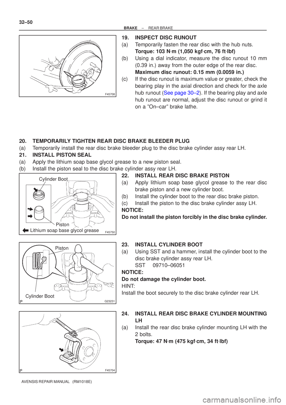
19.INSPECT DISC RUNOUT
(a)Temporarily fasten the rear disc with the hub nuts. Torque: 103 N �m (1,050 kgf �cm, 76 ft �lbf)
(b)Using a dial indicator, measure the disc runout 10 mm (0.39 in.) away from the outer edge of the rear disc.
Maximum disc runout: 0.15 mm (0.0059 in.)
(c)If the disc runout is maximum value or greater, check the
bearing play in the axial direction and check for the axle
hub runout (See page 30±2). If the bearing play and axle
hub runout are normal, adjust the disc runout or grind it
on a ºOn±carº brake lathe.
20. TEMPORARILY TIGHTEN REAR DISC BRAKE BLEEDER PLUG
(a) Temporarily install the rear disc brake bleeder plug to the disc brake cy\
linder assy rear LH.
21. INSTALL PISTON SEAL
(a) Apply the lithium soap base glycol grease to a new piston seal.
(b) Install the piston seal to the disc brake cylinder assy rear LH. 22. INSTALL REAR DISC BRAKE PISTON
(a) Apply lithium soap base glycol grease to the rear discbrake piston and a new cylinder boot.
(b) Install the cylinder boot to the rear disc brake piston.
(c) Install the piston to the disc brake cylinder assy LH.
NOTICE:
Do not install the piston forcibly in the disc brake cylinder.
23. INSTALL CYLINDER BOOT
(a) Using SST and a hammer, install the cylinder boot to the disc brake cylinder assy rear LH.
SST 09710±06051
NOTICE:
Do not damage the cylinder boot.
HINT:
Install the boot securely to the disc brake cylinder rear LH.
24. INSTALL REAR DISC BRAKE CYLINDER MOUNTING LH
(a) Install the rear disc brake cylinder mounting LH with the
2 bolts.
Torque: 47 N �m (475 kgf �cm, 34 ft �lbf)
Page 81 of 1690

F45439
Front Disc Brake Cylinder MountingBush Dust Boot
Lithium soap base glycol grease
F45701
Cylinder Slide Pin
Lithium soap base glycol grease
G23181
Union bolt
±
BRAKE REAR BRAKE
32±51
AVENSIS REPAIR MANUAL (RM1018E)
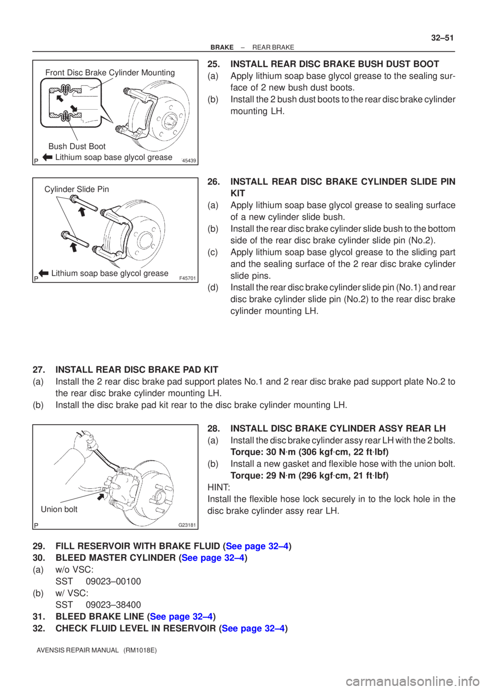
25.INSTALL REAR DISC BRAKE BUSH DUST BOOT
(a)Apply lithium soap base glycol grease to the sealing sur-
face of 2 new bush dust boots.
(b)Install the 2 bush dust boots to the rear disc brake cylinder mounting LH.
26.INSTALL REAR DISC BRAKE CYLINDER SLIDE PIN KIT
(a)Apply lithium soap base glycol grease to sealing surface of a new cylinder slide bush.
(b)Install the rear disc brake cylinder slide bush to the bottom side of the rear disc brake cylinder slide pin (No.2).
(c)Apply lithium soap base glycol grease to the sliding part and the sealing surface of the 2 rear disc brake cylinder
slide pins.
(d)Install the rear disc brake cylinder slide pin (No.1) and rear
disc brake cylinder slide pin (No.2) to the rear disc brake
cylinder mounting LH.
27.INSTALL REAR DISC BRAKE PAD KIT
(a)Install the 2 rear disc brake pad support plates No.1 and 2 rear disc brake pad\
support plate No.2 to the rear disc brake cylinder mounting LH.
(b)Install the disc brake pad kit rear to the disc brake cylinder mounting \
LH.
28.INSTALL DISC BRAKE CYLINDER ASSY REAR LH
(a)Install the disc brake cylinder assy rear LH with the 2 bolts.Torque: 30 N �m (306 kgf �cm, 22 ft �lbf)
(b)Install a new gasket and flexible hose with the union bolt. Torque: 29 N �m (296 kgf �cm, 21 ft �lbf)
HINT:
Install the flexible hose lock securely in to the lock hole in the
disc brake cylinder assy rear LH.
29.FILL RESERVOIR WITH BRAKE FLUID (See page 32±4)
30.BLEED MASTER CYLINDER (See page 32±4)
(a) w/o VSC: SST 09023±00100
(b) w/ VSC: SST 09023±38400
31.BLEED BRAKE LINE (See page 32±4)
32.CHECK FLUID LEVEL IN RESERVOIR (See page 32±4)
Page 117 of 1690
4202X±03
D30055Lithium soap glycol grease
N�m (kgf�cm, ft�lbf) : Specified torque
�Non±reusable part 1CD±FTV Engine Type:
Bleeder PlugRelease Cylinder Body
Piston
Push RodBoot Bleeder Plug
Cap
8.4 (85, 74 in.�lbf)
Wire Harness ClampClutch Accumulator Assy
Spring
1AZ±FSE/1AZ±FE Engine Type:
15 (155, 11)
12 (120, 9)
�
12 (120, 9)
Release Cylinder Body
12 (120, 9)
Release Cylinder Body
Clutch Line Clamp
Clutch Line Bracket
15 (155, 11)
12 (122, 9)
5.0 (51, 44 in.�lbf)1ZZ±FE/3ZZ±FE Engine Type:
15 (155, 11)Clutch Line Clamp
14 (141, 10)
15 (155, 11)
12 (120, 9)
42±16
± CLUTCHCLUTCH RELEASE CYLINDER ASSY (MTM)
AVENSIS REPAIR MANUAL (RM1018E)
CLUTCH RELEASE CYLINDER ASSY (MTM)
COMPONENTS