Page 517 of 1690
A77497
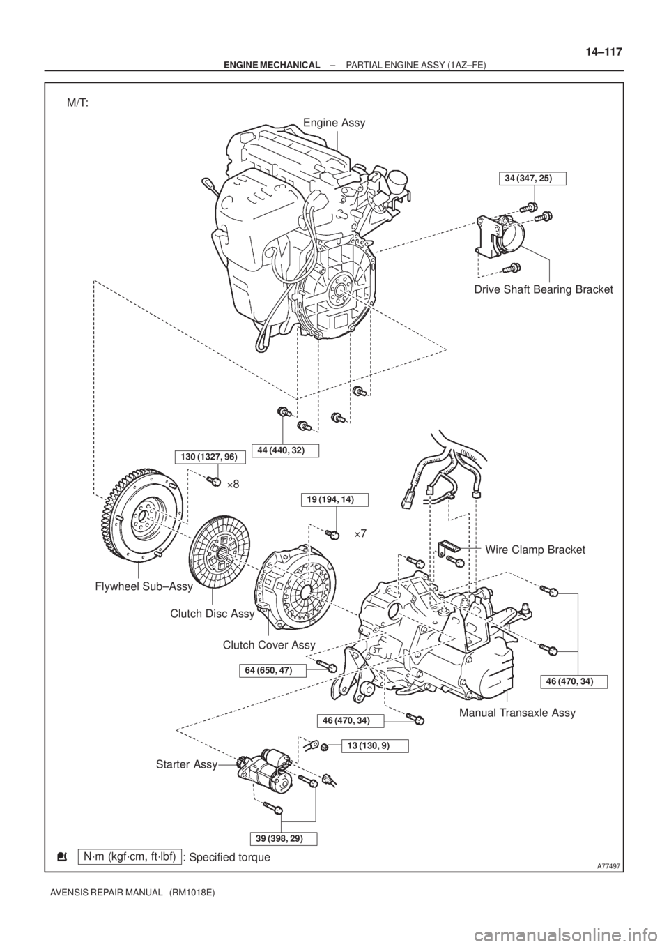
Engine Assy
Drive Shaft Bearing Bracket
Wire Clamp Bracket
Manual Transaxle Assy
Starter AssyClutch Disc Assy Flywheel Sub±Assy�8
�7
Clutch Cover Assy
N´m (kgf´cm, ft´lbf)
: Specified torque M/T:
34 (347, 25)
46 (470, 34)
13 (130, 9)
39 (398, 29)
64 (650, 47)
19 (194, 14)
44 (440, 32)
46 (470, 34)
130 (1327, 96)
± ENGINE MECHANICALPARTIAL ENGINE ASSY (1AZ±FE)
14±117
AVENSIS REPAIR MANUAL (RM1018E)
Page 518 of 1690
A77316
Engine Assy
Drive Shaft Bearing Bracket
Hole Plug
Drive Plate & Ring Gear
Sub±Assyx6
Wire Clamp Bracket
Starter Wire Starter Assy
34 (347, 25)
41 (420, 32)
98 (1,000, 72)
46 (469, 34)
13 (132, 10)
x8
N´m (kgf´cm, ft´lbf)
: Specified torque A/T:
Automatic Transaxle
46 (469, 34)
46 (469, 34)
37 (378, 27)
37 (378, 27)
64 (653, 47)
41 (418, 30)
14±118
± ENGINE MECHANICALPARTIAL ENGINE ASSY (1AZ±FE)
AVENSIS REPAIR MANUAL (RM1018E)
Page 527 of 1690

14±127
AVENSIS REPAIR MANUAL (RM1018E)
63.SEPARATE VANE PUMP ASSY
(a)Disconnect the PS oil pressure switch connector.
(b)Remove th")
A77402SST
A56446
±
ENGINE MECHANICAL PARTIAL ENGINE ASSY(1AZ±FE)
14±127
AVENSIS REPAIR MANUAL (RM1018E)
63.SEPARATE VANE PUMP ASSY
(a)Disconnect the PS oil pressure switch connector.
(b)Remove the 2 bolts and separate the vane pump from the engine.
64.REMOVE STARTER ASSY (See page 19±12)
65.REMOVE FRONT SUSPENSION CROSSMEMBER W/CENTER MEMBER
(a)Remove the through bolt and nut from the engine mounting insulator FR.
(b)Remove the through bolt and nut from the engine mounting insulator RR.
66.REMOVE FRONT DRIVE SHAFT ASSY LH (See page 30±6)
67.REMOVE FRONT DRIVE SHAFT ASSY RH (See page 30±6)
68.REMOVE MANUAL TRANSAXLE ASSY (M/T TRANSAXLE) (See page 41±24)
69.REMOVE AUTOMATIC TRANSAXLE ASSY (A/T TRANSAXLE) (See page 40±25)
70.REMOVE CLUTCH COVER ASSY (M/T TRANSAXLE) (See page 42±26)
71.REMOVE CLUTCH DISC ASSY (M/T TRANSAXLE) (See page 42±26)
72. REMOVE DRIVE PLATE AND RING GEAR ORFLYWHEEL
(a) Using SST, fix the crankshaft pulley and remove the drive plate and ring gear or flywheel.
SST 09213±54015 (91651±60855), 09330±00021
73. REMOVE CAMSHAFT TIMING OIL CONTROL VALVE ASSY (W/ VVT±i)
(a) Remove a bolt, O±ring and the camshaft timing oil control valve. 74. REMOVE INTAKE MANIFOLD
(a) Remove the 5 bolts and 2 nuts, and then remove the in-take manifold.
75. REMOVE VENTILATION HOSE
76. REMOVE VENTILATION HOSE NO.2
77. REMOVE ENGINE WIRE
78. REMOVE INTAKE MANIFOLD INSULATOR NO.1
79. REMOVE OIL LEVEL GAGE SUB±ASSY
80. REMOVE OIL LEVEL GAGE GUIDE
81. REMOVE MANIFOLD CONVERTER INSULATOR NO.1
(a) Remove the 4 bolts and the manifold converter insulator No. 1.
Page 531 of 1690

14±131
AVENSIS REPAIR MANUAL (RM1018E)
(b)Install the drive plate. (A/T)
(1)Clean the bolt and bol")
A77403
15
3
7
2
6
4 8
A63273
A77404
B
A
BBBB
A
B
±
ENGINE MECHANICAL PARTIAL ENGINE ASSY(1AZ±FE)
14±131
AVENSIS REPAIR MANUAL (RM1018E)
(b)Install the drive plate. (A/T)
(1)Clean the bolt and bolt hole.
(2)Apply adhesive to the bolts.
(3)Using several steps, install and tighten the 8 boltsuniformly in the sequence shown in the illustration.
Torque: 98 N �m (1,000 kgf �cm, 72 ft �lbf)
(c)Install the flywheel. (M/T)
(1)Clean the bolt hole.
(2)Using several steps, install and tighten the 8 boltsuniformly in the sequence shown in the illustration.
Torque: 130 N �m (1,327 kgf �cm, 96 ft �lbf)
NOTICE:
Do not reuse the flywheel bolt.
110.INSTALL CLUTCH DISC ASSY (M/T TRANSAXLE) (See page 42±26)
111.INSTALL CLUTCH COVER ASSY (M/T TRANSAXLE) (See page 42±26)
112.INSTALL MANUAL TRANSAXLE ASSY (M/T TRANSAXLE) (See page 41±24)
113.INSTALL AUTOMATIC TRANSAXLE ASSY (A/T TRANSAXLE) (See page 40±25)
114.INSTALL FRONT DRIVE SHAFT ASSY LH (See page 30±6)
115.INSTALL FRONT DRIVE SHAFT ASSY RH (See page 30±6)
116.INSTALL FRONT SUSPENSION CROSSMEMBER W/CENTER MEMBER
(a)Install the engine mounting insulator FR with the through bolt and nut. Torque: 87 N �m (887 kgf �cm,64 ft �lbf)
(b)Install the engine mounting insulator RR with the through bolt and nut. Torque: 87 N �m (887 kgf �cm,64 ft �lbf)
117.INSTALL STARTER ASSY (See page 19±12)
118. INSTALL VANE PUMP ASSY
Torque: 37 N �m (370 kgf �cm, 27 ft �lbf)
119. INSTALL ENGINE ASSEMBLY WITH TRANSAXLE
(a) Install the 2 bolts and 2 nuts as shown in the illustration. Torque:
Bolt 45 N �m (459 kgf �cm, 33 ft �lbf)
Nut 133 N �m (1,356 kgf �cm, 98 ft �lbf)
(b) Install the front suspension member braces with the 8 bolts.
Torque:
Bolt A 133 N �m (1,356 kgf �cm, 98 ft �lbf)
Bolt B 80 N �m (816 kgf �cm, 59 ft �lbf)
Page 539 of 1690
A79421N´m (kgf´cm, ft´lbf)
: Specified torque
88 (897, 65)
19 (195, 14)
64 (653, 47)
37 (377, 27)
Drive Shaft Bearing Bracket
Flywheel Sub±assy
Clutch Cover Assy
Starter Assy
Manual Transaxle
Clutch Disc Assy
64 (653, 47)
± ENGINE MECHANICALPARTIAL ENGINE ASSY (1CD±FTV)
14±281
AVENSIS REPAIR MANUAL (RM1018E)
Page 548 of 1690

AVENSIS REPAIR MANUAL (RM1018E)
(i)Attach the engine sling and hang the engine with the chain block.
44.REMOVE FRO")
A62711
A79180
A61186
SST
14±290
±
ENGINE MECHANICAL PARTIAL ENGINE ASSY(1CD±FTV)
AVENSIS REPAIR MANUAL (RM1018E)
(i)Attach the engine sling and hang the engine with the chain block.
44.REMOVE FRONT SUSPENSION CROSSMEMBER SUB±ASSY
(a)Remove the through bolt and nut, detach the engine mounting insulator FR from the engine mounting bracket.
(b)Remove the through bolt, detach the engine mounting in- sulator RR from the suspension crossmember.
(c)Separate the engine and transaxle assembly from the suspension crossmember and engine mounting member.
45.REMOVE STARTER ASSY (See page 19±24)
46.REMOVE MANUAL TRANSAXLE (See page 41±33)
47.REMOVE CLUTCH DISC ASSY (See page 42±26) 48. REMOVE FLYWHEEL SUB±ASSY
(a) Hold the crank shaft with SST.SST 09213±54015 (90105±08076), 09330±00021
(b) Using a torx socket wrench (T55), remove the 8 torx
screws and the flywheel.
49. REMOVE REAR END PLATE
(a) Remove the 2 bolts and the rear end plate.
50. REMOVE DRIVE SHAFT BEARING BRACKET
51. REMOVE ENGINE MOUNTING BRACKET FR
52. REMOVE ENGINE MOUNTING BRACKET RR
53.REMOVE GLOW PLUG ASSY (See page 19±33)
54.REMOVE GENERATOR V BELT (See page 14±269)
55.REMOVE CRANKSHAFT PULLEY (See page 14±307) SST 09213±54015 (90105±08076), 09330±00021, 09950±50013 (0995\
1±05010, 09952±05010, 09953±05020, 09954±05031)
Page 559 of 1690

14±301
AVENSIS REPAIR MANUAL (RM1018E)
(d)Using several steps, install and tighten the 8 screws with
a")
A79183
2
1
3
4
5
6
7
8
A79180
A62711
A59792
±
ENGINE MECHANICAL PARTIAL ENGINE ASSY(1CD±FTV)
14±301
AVENSIS REPAIR MANUAL (RM1018E)
(d)Using several steps, install and tighten the 8 screws with
a torx socket wrench (T55) uniformly in the sequence
shown in the illustration.
Torque: 71 N �m (720 kgf �cm, 52 ft �lbf)
166.INSTALL CLUTCH DISC ASSY (See page 42±26) SST 09301±00210
167.INSTALL MANUAL TRANSAXLE (See page 41±33)
168.INSTALL STARTER ASSY (See page 19±24)
169. INS TALL FRO NT SUSPENSION CROSSMEMBER
SUB±ASSY
(a) Attach the engine and the transaxle assembly to the sus- pension crossmember and engine mounting member.
(b) Install the bolt which is used to secure the rear engine
mounting bracket to the mounting insulator.
Torque: 87 N �m (887 kgf �cm, 64 ft �lbf)
(c) Install the bolt which is used to secure the front engine mounting bracket to the mounting insulator.
Torque: 52 N �m (530 kgf �cm, 38 ft �lbf)
170. INSTALL ENGINE ASSEMBLY WITH TRANSAXLE
(a) Set the engine assembly with transaxle on the engine lift-
er.
(b) Temporarily, install the suspension crossmember with the 2 bolts and 2 nuts.
(c) Install the engine mounting insulator LH.
Torque: 80 N �m (816 kgf �cm, 59 ft �lbf)
(d) Install the engine mounting insulator RH. Torque: 52 N �m (530 kgf �cm, 38 ft �lbf)
Page 568 of 1690
A79349N´m (kgf´cm, ft´lbf): Specified torqueAutomatic Transaxle Assy
Drive Plate Spacer
RR
Drive Plate & Ring Gear Sub±assy
Drive Plate Spacer
FR
A/T:
28 (286, 21)
88 (897, 65)
Clutch Disk Assy
Clutch Cover Assy
Manual Transaxle Assy
Starter Assy
Flywheel Sub±assy
See page 14±27
1st 49 (500, 36)
2nd Turn 90 �
37 (377, 27)
37 (377, 27)
64 (653, 47)
19 (194, 14)
64 (653, 47)
9.8 (100, 7)
47 (479, 35)
47 (479, 35)
14±24
±
ENGINE MECHANICAL PARTIAL ENGINE ASSY (1ZZ±FE/3ZZ±FE)
AVENSIS REPAIR MANUAL (RM1018E)

41 (420, 32)
98 (1,000, 72)
46 (469, 34)
13 (132")

: Specified torque
88 (897, 65)
19 (195, 14)
64 (653, 47)
37 (377, 27)
Drive Shaft Bearing Bracket
Flywheel Sub±assy
Clutch Cover Assy
Starter Assy
Manual Transaxle
Clut")
: Specified torqueAutomatic Transaxle Assy
Drive Plate Spacer
RR
Drive Plate & Ring Gear Sub±assy
Drive Plate Spacer
FR
A/T:
28 (286, 21)
88 (897, 65)
Clutch Disk Assy")