Page 434 of 1690
A77302
14±162
±
ENGINE MECHANICAL CYLINDER HEAD GASKET(1AZ±FE)
AVENSIS REPAIR MANUAL (RM1018E)
22.REMOVE ENGINE SERVICE COVER BRACKET RH (RHD(W/ AIR CONDITIONER) STEERING POSITION TYPE)
(a)Remove the bolt and the engine service cover bracket RH.
23.REMOVE CYLINDER HEAD COVER SUB±ASSY (See page 14±139)
24.SET NO. 1 CYLINDER TO TDC/COMPRESSION (See page 14±139)
25.REMOVE ENGINE MOUNTING BRACKET NO.2 RH (See page 14±139)
26.REMOVE TRANSVERSE ENGINE ENGINE MOUNTING INSULATOR (See page 14±139)
27.REMOVE CRANKSHAFT PULLEY (See page 14±139)
SST09213±54015 (91651±60855), 09330±00021, 09950±50013 (0995\
1±05010, 09952±05010, 09953±05020, 09954±05021)
28.REMOVE CHAIN TENSIONER ASSY NO.1 (See page 14±139)
29.REMOVE CRANKSHAFT POSITION SENSOR (See page 18±17)
30.REMOVE OIL PAN SUB±ASSY (See page 14±139) SST09032±00100
31.REMOVE V±RIBBED BELT TENSIONER ASSY (See page 14±139)
32.REMOVE TIMING CHAIN OR BELT COVER SUB±ASSY (See page 14±139)
33.REMOVE CRANKSHAFT POSITION SENSOR PLATE NO.1
34.REMOVE CHAIN TENSIONER SLIPPER
35.REMOVE CHAIN VIBRATION DAMPER NO.1
36.REMOVE TIMING CHAIN GUIDE (See page 14±139)
37.REMOVE CHAIN SUB±ASSY
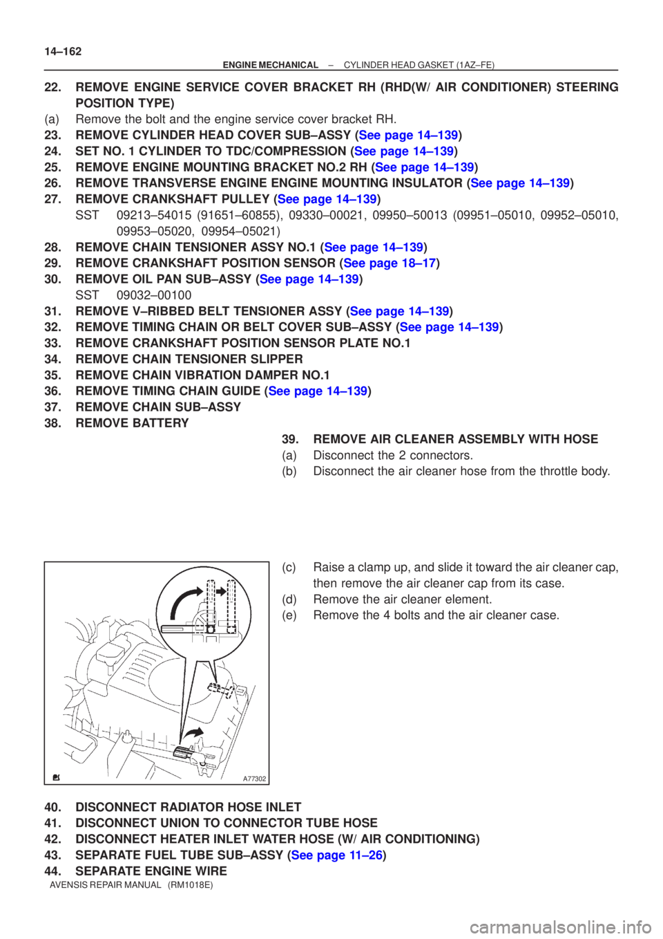
38.REMOVE BATTERY 39.REMOVE AIR CLEANER ASSEMBLY WITH HOSE
(a)Disconnect the 2 connectors.
(b)Disconnect the air cleaner hose from the throttle body.
(c)Raise a clamp up, and slide it toward the air cleaner cap,then remove the air cleaner cap from its case.
(d)Remove the air cleaner element.
(e)Remove the 4 bolts and the air cleaner case.
40.DISCONNECT RADIATOR HOSE INLET
41.DISCONNECT UNION TO CONNECTOR TUBE HOSE
42.DISCONNECT HEATER INLET WATER HOSE (W/ AIR CONDITIONING)
43.SEPARATE FUEL TUBE SUB±ASSY (See page 11±26)
44. SEPARATE ENGINE WIRE
Page 443 of 1690
A77302
A77353
±
ENGINE MECHANICAL CYLINDER HEAD GASKET(1AZ±FSE)
14±257
AVENSIS REPAIR MANUAL (RM1018E)
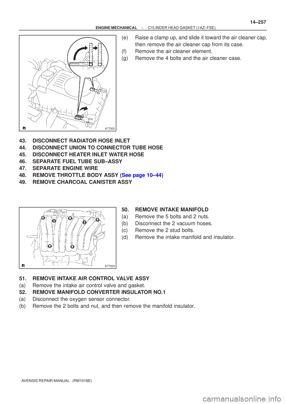
(e)Raise a clamp up, and slide it toward the air cleaner cap,
then remove the air cleaner cap from its case.
(f)Remove the air cleaner element.
(g)Remove the 4 bolts and the air cleaner case.
43.DISCONNECT RADIATOR HOSE INLET
44.DISCONNECT UNION TO CONNECTOR TUBE HOSE
45.DISCONNECT HEATER INLET WATER HOSE
46.SEPARATE FUEL TUBE SUB±ASSY
47.SEPARATE ENGINE WIRE
48.REMOVE THROTTLE BODY ASSY (See page 10±44)
49. REMOVE CHARCOAL CANISTER ASSY 50. REMOVE INTAKE MANIFOLD
(a) Remove the 5 bolts and 2 nuts.
(b) Disconnect the 2 vacuum hoses.
(c) Remove the 2 stud bolts.
(d) Remove the intake manifold and insulator.
51. REMOVE INTAKE AIR CONTROL VALVE ASSY
(a) Remove the intake air control valve and gasket.
52. REMOVE MANIFOLD CONVERTER INSULATOR NO.1
(a) Disconnect the oxygen sensor connector.
(b) Remove the 2 bolts and nut, and then remove the manifold insulator.
Page 454 of 1690
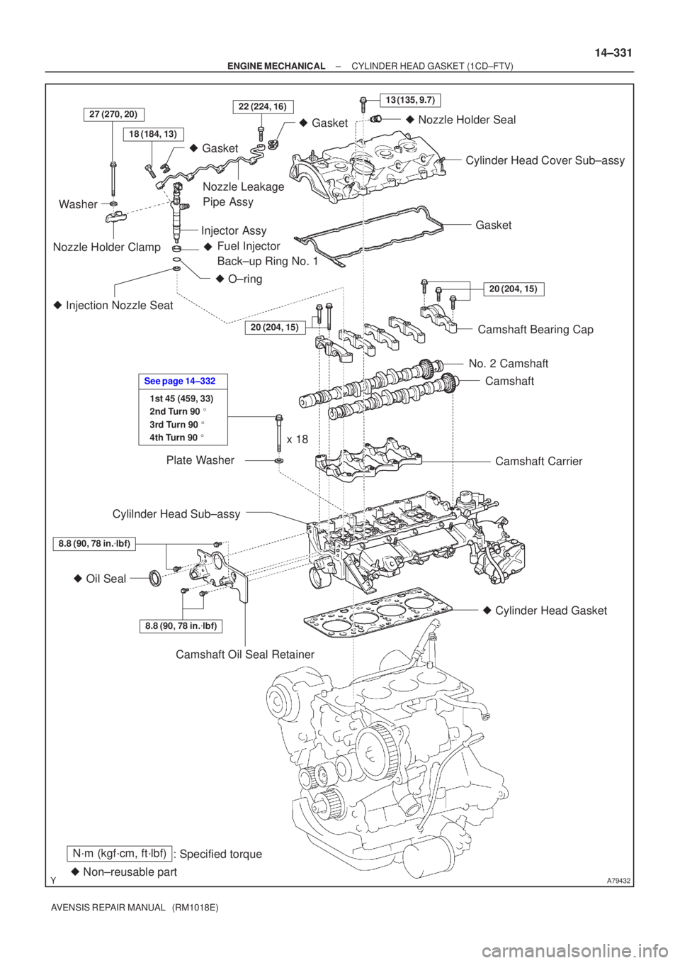
A79432
N´m (kgf´cm, ft´lbf): Specified torque
� Non±reusable part �
Gasket
18 (184, 13)
27 (270, 20)22 (224, 16)13 (135, 9.7)
� Gasket
� O±ring
Fuel Injector
Back±up Ring No. 1
�
� Injection Nozzle Seat
20 (204, 15)
8.8 (90, 78 in. �lbf)
� Oil Seal
8.8 (90, 78 in. �lbf)
1st 45 (459, 33)
2nd Turn 90 �
3rd Turn 90 �
4th Turn 90 �
See page 14±332
20 (204, 15)
Washer
Nozzle Holder Clamp Nozzle Leakage
Pipe Assy
Injector Assy �
Nozzle Holder Seal
Cylinder Head Cover Sub±assy
Gasket
Camshaft Bearing Cap
No. 2 Camshaft Camshaft
Camshaft Carrier
� Cylinder Head Gasket
Camshaft Oil Seal Retainer
Cylilnder Head Sub±assy
Plate Washer
x 18
±
ENGINE MECHANICAL CYLINDER HEAD GASKET (1CD±FTV)
14±331
AVENSIS REPAIR MANUAL (RM1018E)
Page 466 of 1690
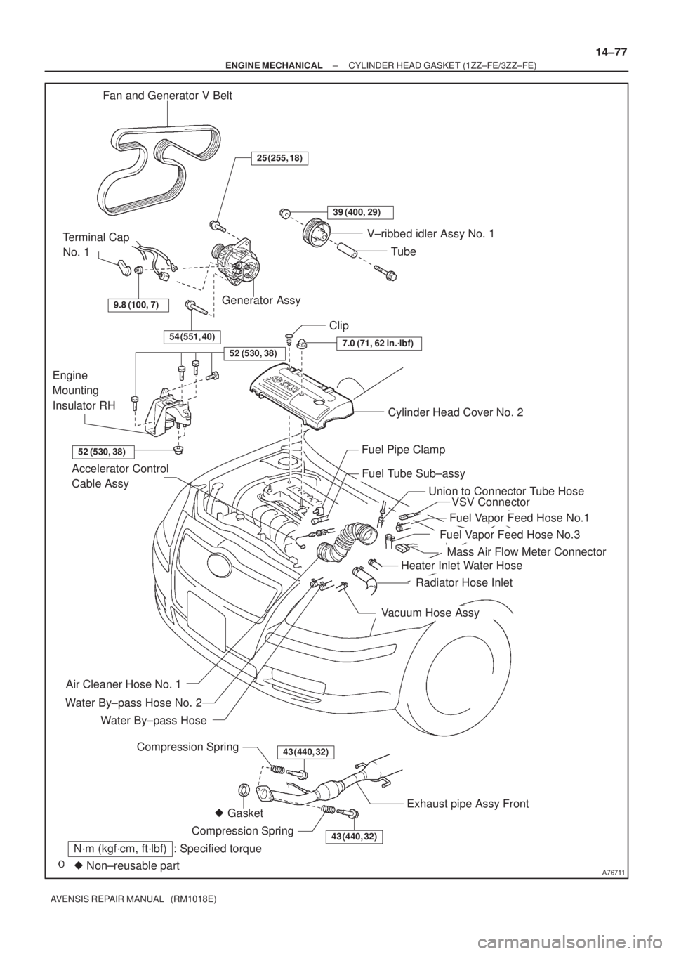
A76711
Fan and Generator V Belt
Generator Assy Terminal Cap
No. 1
Cylinder Head Cover No. 2 Clip
Fuel Pipe Clamp
Fuel Tube Sub±assy
Water By±pass Hose
Water By±pass Hose No. 2
Accelerator Control
Cable Assy
Heater Inlet Water Hose
Radiator Hose Inlet
Air Cleaner Hose No. 1
� GasketExhaust pipe Assy Front
Compression Spring43 (440, 32)
43 (440, 32)Compression Spring
� Non±reusable part
N´m (kgf´cm, ft´lbf) : Specified torque
V±ribbed idler Assy No. 1
Tube
54 (551, 40)
9.8 (100, 7)
25 (255, 18)
39 (400, 29)
7.0 (71, 62 in.�lbf)
52 (530, 38)
52 (530, 38)
Union to Connector Tube Hose
Fuel Vapor Feed Hose No.1
Fuel Vapor Feed Hose No.3
Vacuum Hose Assy
Engine
Mounting
Insulator RH
VSV Connector
Mass Air Flow Meter Connector
± ENGINE MECHANICALCYLINDER HEAD GASKET (1ZZ±FE/3ZZ±FE)
14±77
AVENSIS REPAIR MANUAL (RM1018E)
Page 544 of 1690
141C4±01
A80094
14±286
±
ENGINE MECHANICAL PARTIAL ENGINE ASSY(1CD±FTV)
AVENSIS REPAIR MANUAL (RM1018E)
REPLACEMENT
1.REMOVE FRONT WHEELS
2.REMOVE ENGINE UNDER COVER LH
3.REMOVE ENGINE UNDER COVER SUB±ASSY NO.1
4.REMOVE ENGINE UNDER COVER RH
5.REMOVE RADIATOR SUPPORT OPENING COVER
6.REMOVE ENGINE ROOM COVER SIDE
7.DRAIN ENGINE COOLANT (See page 16±44)
8.DRAIN ENGINE OIL (See page 14±342)
9.DRAIN MANUAL TRANSAXLE OIL Torque: 49 N �m (500 kgf �cm,36 ft �lbf)
10.REMOVE ENGINE COVER NO.1
(a)Remove the 5 nuts and the engine cover.
11.REMOVE BATTERY
12.REMOVE AIR CLEANER ASSY
(a)Disconnect the connector.
(b)Remove the air cleaner cap together with the air cleaner hose.
(c)Remove the air cleaner filter element.
(d)Remove the 3 bolts and the air cleaner case.
13.DISCONNECT UNION TO CONNECTOR TUBE HOSE
14.REMOVE FUEL FILTER ASSY
(a)Disconnect the 2 fuel hose from the fuel filter (STD).
(b)Disconnect the 3 fuel hose from the fuel filter (COLD).
(c)Disconnect the connector (STD).
(d)Disconnect the 2 connectors (COLD).
(e)Remove the 2 bolts and the fuel filter.
15.REMOVE RADIATOR HOSE INLET
16.REMOVE RADIATOR HOSE OUTLET
17.DISCONNECT WATER BY±PASS HOSE NO.2
18.REMOVE ENGINE ROOM RELAY BLOCK NO.3
(a)Remove the 2 bolts and the engine room relay block.
19.REMOVE RADIATOR ASSY (W/ AIR CONDITIONING) (See page 16±51)
20. DISCONNECT HEATER INLET WATER HOSE
21. DISCONNECT HEATER OUTLET WATER HOSE
22. DISCONNECT FUEL HOSE NO.2
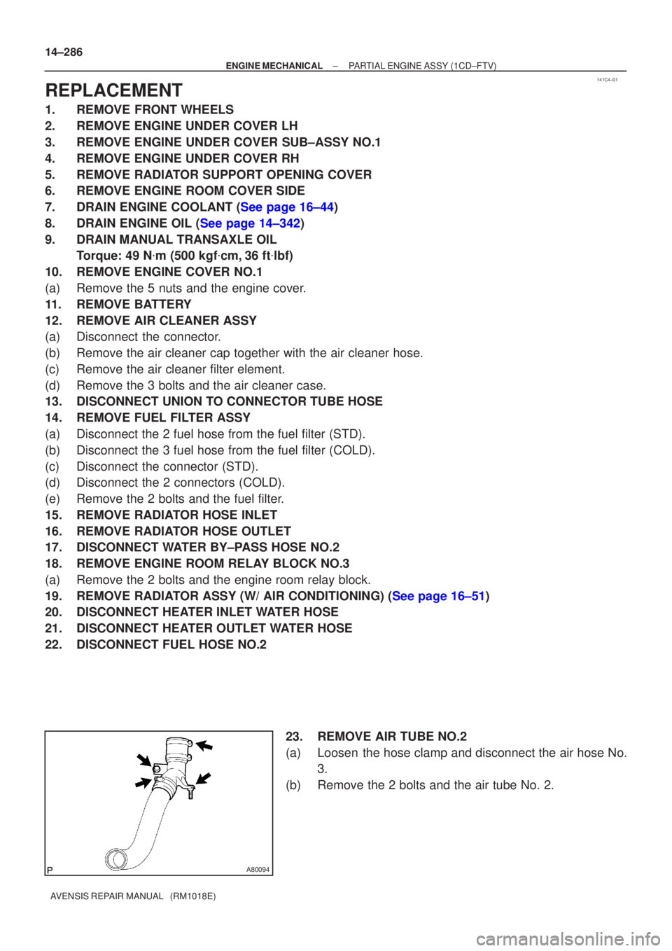
23. REMOVE AIR TUBE NO.2
(a) Loosen the hose clamp and disconnect the air hose No.3.
(b) Remove the 2 bolts and the air tube No. 2.
Page 564 of 1690
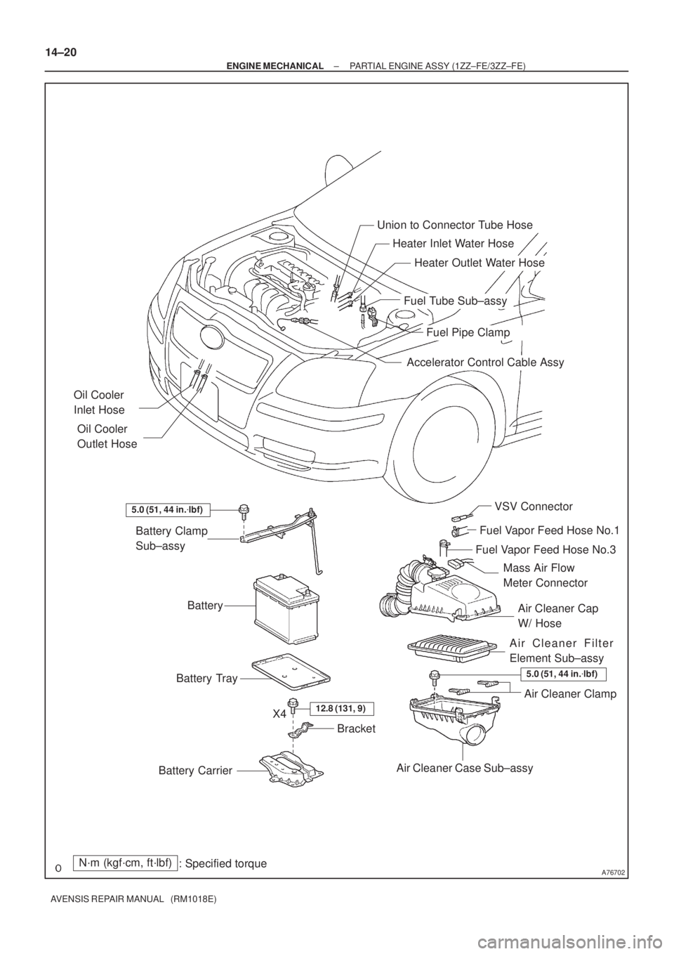
A76702
Accelerator Control Cable Assy
Heater Inlet Water Hose
Fuel Pipe Clamp
Fuel Tube Sub±assy
Heater Outlet Water Hose
Air Cleaner Cap
W/ Hose
Air Cleaner Filter
Element Sub±assy
Air Cleaner Case Sub±assy Battery Clamp
Sub±assy
Battery
Battery Tray
Battery Carrier
12.8 (131, 9)
N´m (kgf´cm, ft´lbf)
: Specified torque
Union to Connector Tube Hose
Air Cleaner Clamp
Bracket
5.0 (51, 44 in.�lbf)
Fuel Vapor Feed Hose No.1
Fuel Vapor Feed Hose No.3
5.0 (51, 44 in.�lbf)
Oil Cooler
Inlet Hose
Oil Cooler
Outlet Hose
X4
VSV Connector
Mass Air Flow
Meter Connector
14±20
± ENGINE MECHANICALPARTIAL ENGINE ASSY (1ZZ±FE/3ZZ±FE)
AVENSIS REPAIR MANUAL (RM1018E)
Page 728 of 1690
110UD±01
A79188
A80091SST
A79190
11±82
± FUELFUEL FILTER ASSY (1CD±FTV)
AVENSIS REPAIR MANUAL (RM1018E)
FUEL FILTER ASSY (1CD±FTV)
REPLACEMENT
1. REMOVE AIR CLEANER ASSY
(a) Disconnect the connector.
(b) Remove the air cleaner cap with the air cleaner hose.
(c) Remove the air cleaner filter element.
(d) Remove the 3 bolts and the air cleaner case.
2. REMOVE FUEL FILTER ASSY
(a) Disconnect the 2 fuel hose from the fuel filter. (STD or COLD)
(b) Disconnect the 3 fuel hose from the fuel filter. (W/ ADDTIONAL HEATER)
(c) Disconnect the 2 connectors.
(d) Remove the 2 bolts and the fuel filter.
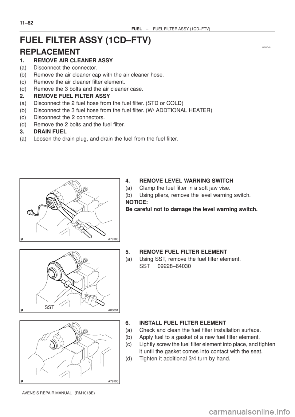
3. DRAIN FUEL
(a) Loosen the drain plug, and drain the fuel from the fuel filter.
4. REMOVE LEVEL WARNING SWITCH
(a) Clamp the fuel filter in a soft jaw vise.
(b) Using pliers, remove the level warning switch.
NOTICE:
Be careful not to damage the level warning switch.
5. REMOVE FUEL FILTER ELEMENT
(a) Using SST, remove the fuel filter element.
SST 09228±64030
6. INSTALL FUEL FILTER ELEMENT
(a) Check and clean the fuel filter installation surface.
(b) Apply fuel to a gasket of a new fuel filter element.
(c) Lightly screw the fuel filter element into place, and tighten
it until the gasket comes into contact with the seat.
(d) Tighten it additional 3/4 turn by hand.
Page 730 of 1690
110U0±01
A79730
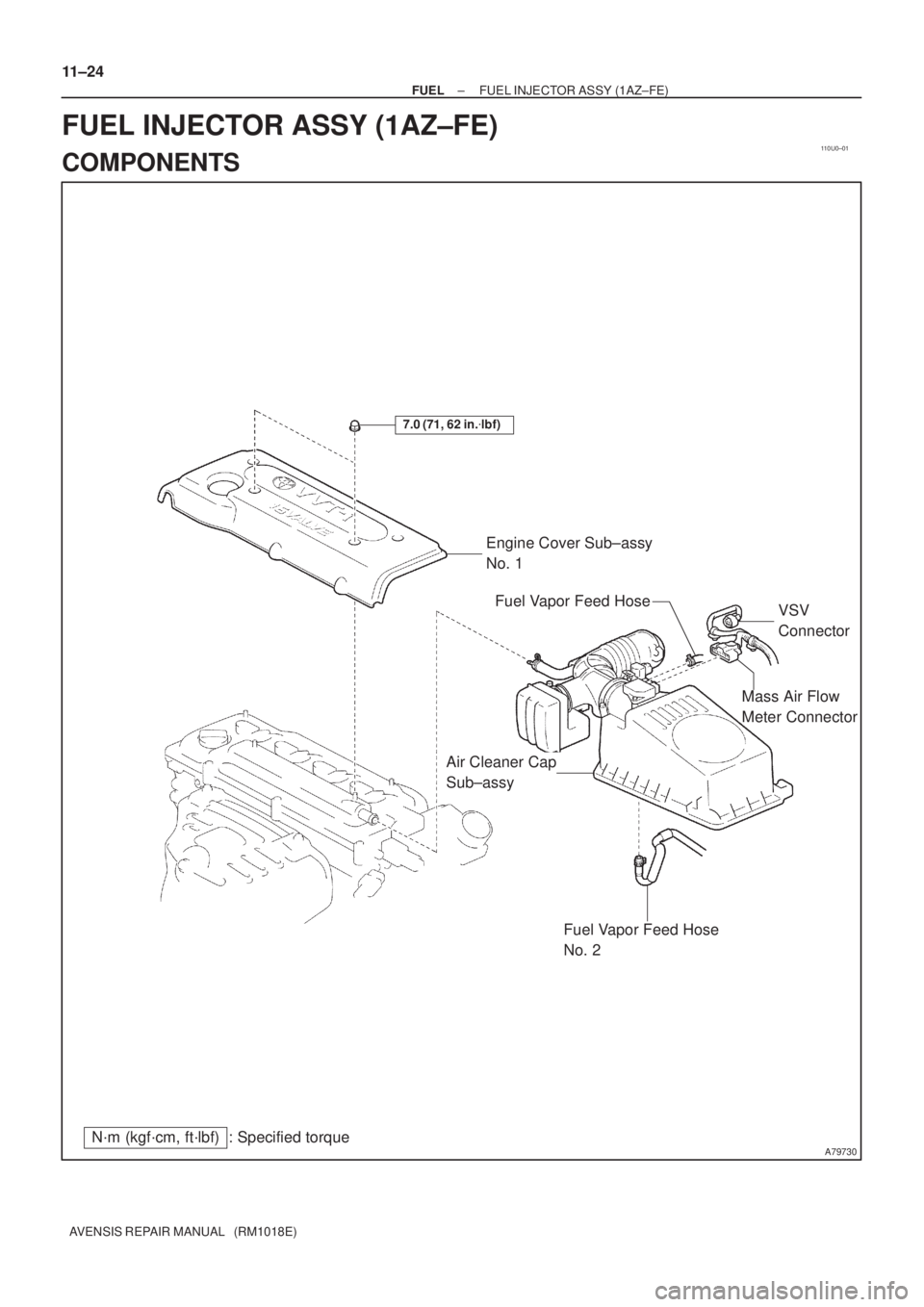
Mass Air Flow
Meter Connector
N´m (kgf´cm, ft´lbf) : Specified torqueEngine Cover Sub±assy
No. 1
7.0 (71, 62 in.�lbf)
Fuel Vapor Feed Hose
No. 2
Air Cleaner Cap
Sub±assyVSV
Connector Fuel Vapor Feed Hose
11±24
± FUELFUEL INJECTOR ASSY (1AZ±FE)
AVENSIS REPAIR MANUAL (RM1018E)
FUEL INJECTOR ASSY (1AZ±FE)
COMPONENTS