Page 48 of 1690
F45361
F45362
F45367
F45363Vacuum tank
C81275
± BRAKEBRAKE BOOSTER ASSY (RHD)
32±27
AVENSIS REPAIR MANUAL (RM1018E)
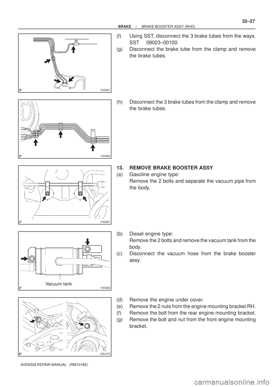
(f) Using SST, disconnect the 3 brake tubes from the ways.
SST 09023±00100
(g) Disconnect the brake tube from the clamp and remove
the brake tubes.
(h) Disconnect the 3 brake tubes from the clamp and remove
the brake tubes.
13. REMOVE BRAKE BOOSTER ASSY
(a) Gasoline engine type:
Remove the 2 bolts and separate the vacuum pipe from
the body.
(b) Diesel engine type:
Remove the 2 bolts and remove the vacuum tank from the
body.
(c) Disconnect the vacuum hose from the brake booster
assy.
(d) Remove the engine under cover.
(e) Remove the 2 nuts from the engine mounting bracket RH.
(f) Remove the bolt from the rear engine mounting bracket.
(g) Remove the bolt and nut from the front engine mounting
bracket.
Page 50 of 1690
C80805
C82119
C81275
C81274
F45367
± BRAKEBRAKE BOOSTER ASSY (RHD)
32±29
AVENSIS REPAIR MANUAL (RM1018E)
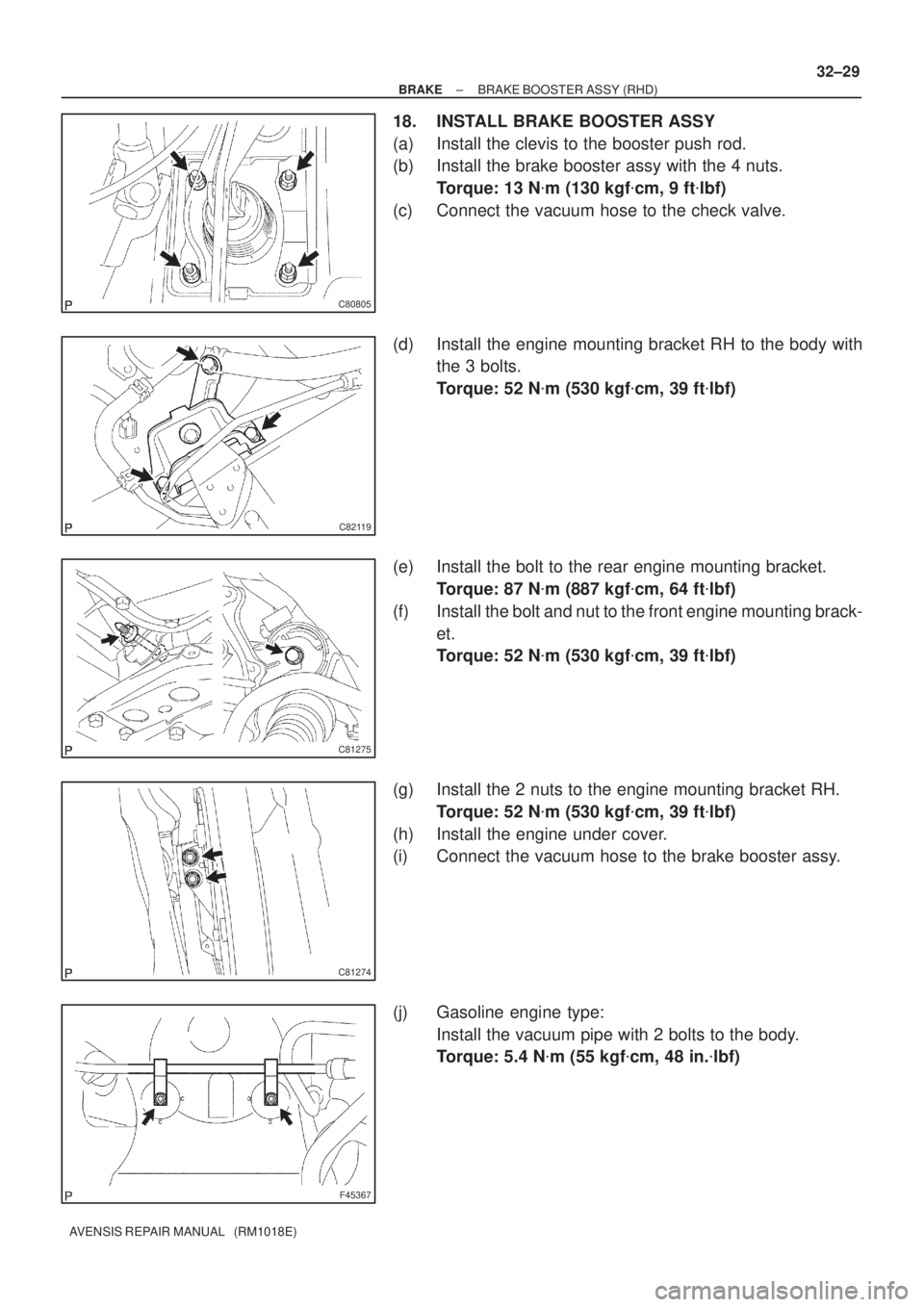
18. INSTALL BRAKE BOOSTER ASSY
(a) Install the clevis to the booster push rod.
(b) Install the brake booster assy with the 4 nuts.
Torque: 13 N�m (130 kgf�cm, 9 ft�lbf)
(c) Connect the vacuum hose to the check valve.
(d) Install the engine mounting bracket RH to the body with
the 3 bolts.
Torque: 52 N�m (530 kgf�cm, 39 ft�lbf)
(e) Install the bolt to the rear engine mounting bracket.
Torque: 87 N�m (887 kgf�cm, 64 ft�lbf)
(f) Install the bolt and nut to the front engine mounting brack-
et.
Torque: 52 N�m (530 kgf�cm, 39 ft�lbf)
(g) Install the 2 nuts to the engine mounting bracket RH.
Torque: 52 N�m (530 kgf�cm, 39 ft�lbf)
(h) Install the engine under cover.
(i) Connect the vacuum hose to the brake booster assy.
(j) Gasoline engine type:
Install the vacuum pipe with 2 bolts to the body.
Torque: 5.4 N�m (55 kgf�cm, 48 in.�lbf)
Page 144 of 1690
160MK±01
A76724
A79300Upper Hook
±
COOLING RADIATOR ASSY(1ZZ±FE/3ZZ±FE)
16±11
AVENSIS REPAIR MANUAL (RM1018E)
RADIATOR ASSY(1ZZ±FE/3ZZ±FE)
REPLACEMENT
1.REMOVE RADIATOR SUPPORT OPENING COVER (See page 14±27)
2.REMOVE ENGINE ROOM COVER SIDE (See page 14±27)
3.ENGINE UNDER COVER SUB±ASSY NO.1 (See page 14±27)
4.DRAIN ENGINE COOLANT (See page 16±1)
5. DISCONNECT RADIATOR HOSE INLET
(a) Disconnect the radiator hose inlet from the radiator.
6. DISCONNECT RADIATOR HOSE OUTLET
(a) Disconnect the radiator hose outlet from the radiator.
7. DISCONNECT OIL COOLER INLET TUBE NO.1 (A/T TRANSAXLE)
(a) Disconnect the oil cooler inlet tube from the radiator.
8. DISCONNECT OIL COOLER OUTLET TUBE NO.1 (A/T TRANSAXLE)
(a) Disconnect the oil cooler outlet tube from the radiator.
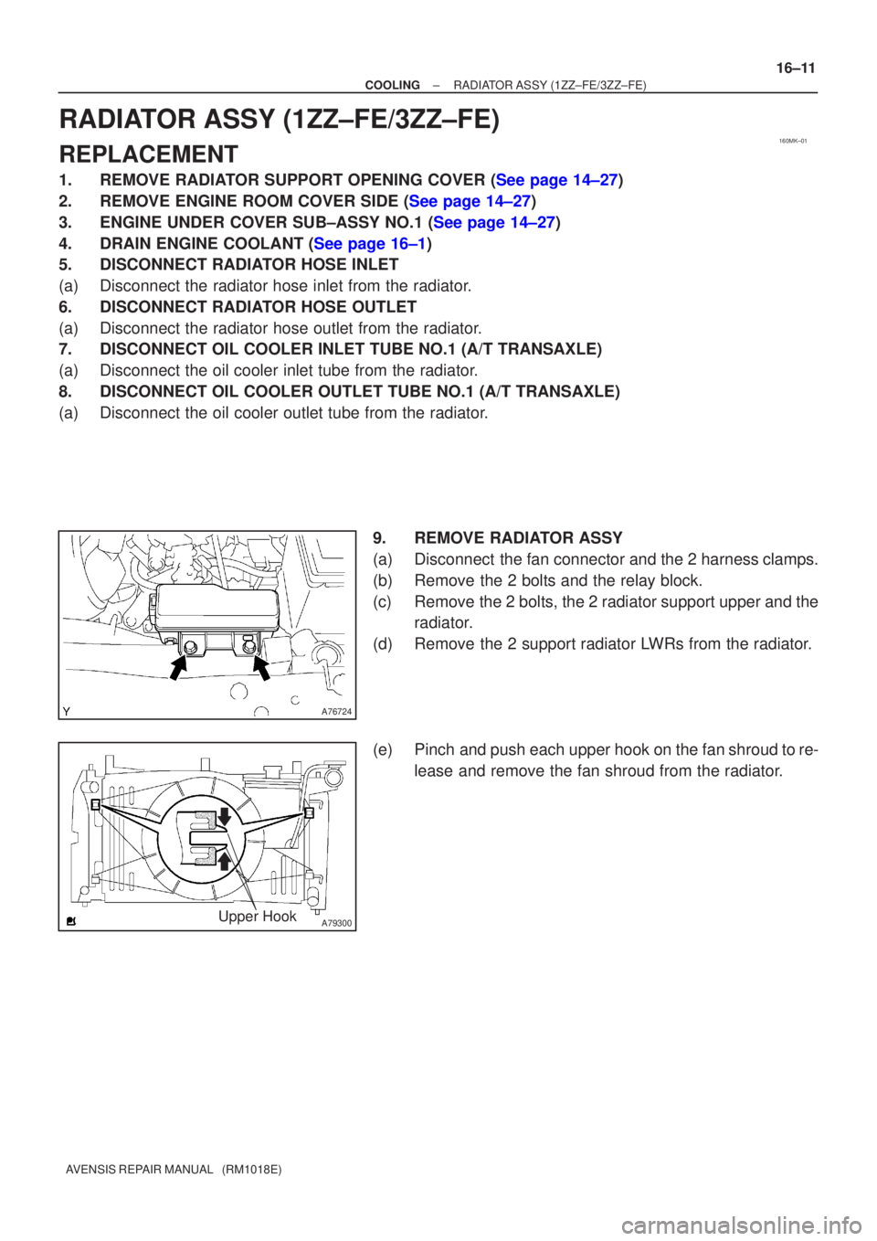
9. REMOVE RADIATOR ASSY
(a) Disconnect the fan connector and the 2 harness clamps.
(b) Remove the 2 bolts and the relay block.
(c) Remove the 2 bolts, the 2 radiator support upper and theradiator.
(d) Remove the 2 support radiator LWRs from the radiator.
(e) Pinch and push each upper hook on the fan shroud to re- lease and remove the fan shroud from the radiator.
Page 170 of 1690
160MX±01
16±24
±
COOLING RADIATOR ASSY(1AZ±FE)
AVENSIS REPAIR MANUAL (RM1018E)
RADIATOR ASSY(1AZ±FE)
REPLACEMENT
1.DRAIN COOLANT (See page 16±19)
2.REMOVE RADIATOR SUPPORT OPENING COVER
3.REMOVE ENGINE ROOM COVER SIDE
4.REMOVE ENGINE UNDER COVER RH
5.DISCONNECT RADIATOR HOSE INLET
6.DISCONNECT RADIATOR HOSE OUTLET
7.REMOVE RADIATOR SUPPORT UPPER
(a)Disconnect the fan w/ motor wire harness, connector and the horn connect\
or.
(b)Remove 4 bolts, the nut and the radiator support.
8.REMOVE RADIATOR ASSY
(a)Remove 2 upper support, and radiator assembly
9.REMOVE RADIATOR SUPPORT LOWER
10.REMOVE FAN ASSY W/MOTOR
(a)Remove 6 bolts and fan w/motor.
11.INSTALL FAN ASSY W/MOTOR
12.INSTALL RADIATOR SUPPORT LOWER
13.INSTALL RADIATOR ASSY
14.INSTALL RADIATOR SUPPORT UPPER
(a)Install radiator support with 2 bolts. Torque: 19 N �m (194 kgf �cm,14 ft �lbf)
15.ADD COOLANT (See page 16±19)
16.INSPECT CHECK FOR ENGINE COOLANT LEAKS (See page 16±13)
Page 171 of 1690
160MS±01
16±36
±
COOLING RADIATOR ASSY(1AZ±FSE)
AVENSIS REPAIR MANUAL (RM1018E)
RADIATOR ASSY(1AZ±FSE)
REPLACEMENT
1.DRAIN COOLANT (See page 16±31)
2.REMOVE RADIATOR SUPPORT OPENING COVER
3.REMOVE ENGINE ROOM COVER SIDE
4.REMOVE ENGINE UNDER COVER RH
5.DISCONNECT RADIATOR HOSE INLET
6.DISCONNECT RADIATOR HOSE OUTLET
7.REMOVE RADIATOR SUPPORT UPPER
(a)Disconnect the fan w/ motor wire harness, connector and the horn connect\
or.
(b)Remove 4 bolts, the nut and the radiator support.
8.REMOVE RADIATOR ASSY
(a)Remove 2 upper support, and radiator assembly
9.REMOVE RADIATOR SUPPORT LOWER
10.REMOVE FAN ASSY W/MOTOR
(a)Remove 6 bolts and fan w/motor.
11.INSTALL FAN ASSY W/MOTOR
12.INSTALL RADIATOR SUPPORT LOWER
13.INSTALL RADIATOR ASSY
14.INSTALL RADIATOR SUPPORT UPPER
(a)Install radiator support with 2 bolts. Torque: 19 N �m (194 kgf �cm,14 ft �lbf)
15.ADD COOLANT (See page 16±31)
16.INSPECT CHECK FOR ENGINE COOLANT LEAKS (See page 16±25)
Page 173 of 1690
160MK±01
A76724
A79300Upper Hook
±
COOLING RADIATOR ASSY(1ZZ±FE/3ZZ±FE)
16±11
AVENSIS REPAIR MANUAL (RM1018E)
RADIATOR ASSY(1ZZ±FE/3ZZ±FE)
REPLACEMENT
1.REMOVE RADIATOR SUPPORT OPENING COVER (See page 14±27)
2.REMOVE ENGINE ROOM COVER SIDE (See page 14±27)
3.ENGINE UNDER COVER SUB±ASSY NO.1 (See page 14±27)
4.DRAIN ENGINE COOLANT (See page 16±1)
5. DISCONNECT RADIATOR HOSE INLET
(a) Disconnect the radiator hose inlet from the radiator.
6. DISCONNECT RADIATOR HOSE OUTLET
(a) Disconnect the radiator hose outlet from the radiator.
7. DISCONNECT OIL COOLER INLET TUBE NO.1 (A/T TRANSAXLE)
(a) Disconnect the oil cooler inlet tube from the radiator.
8. DISCONNECT OIL COOLER OUTLET TUBE NO.1 (A/T TRANSAXLE)
(a) Disconnect the oil cooler outlet tube from the radiator.
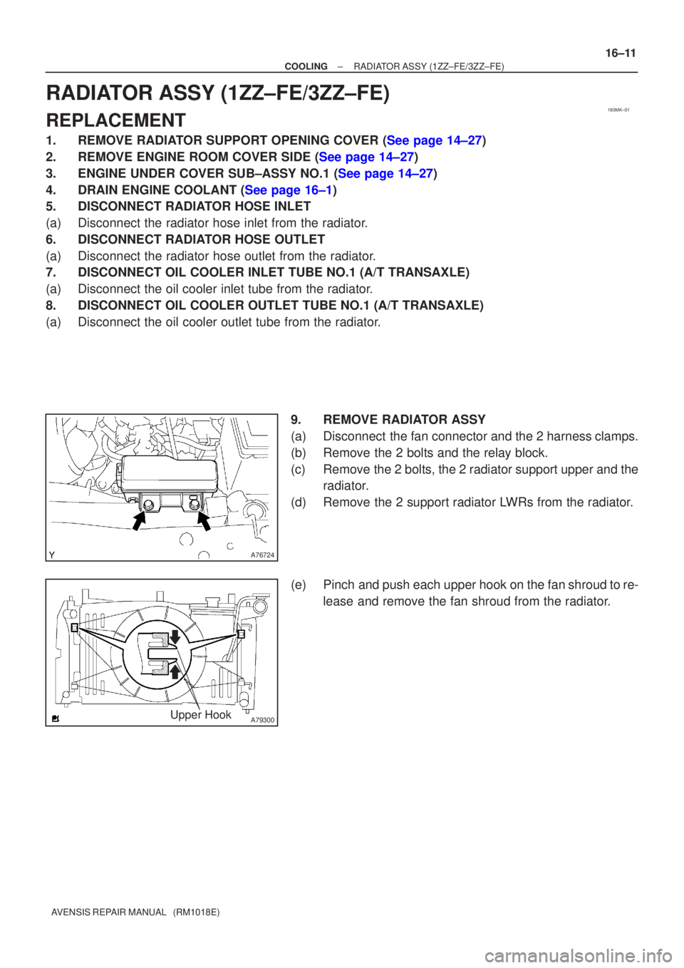
9. REMOVE RADIATOR ASSY
(a) Disconnect the fan connector and the 2 harness clamps.
(b) Remove the 2 bolts and the relay block.
(c) Remove the 2 bolts, the 2 radiator support upper and theradiator.
(d) Remove the 2 support radiator LWRs from the radiator.
(e) Pinch and push each upper hook on the fan shroud to re- lease and remove the fan shroud from the radiator.
Page 175 of 1690
160MQ±01
A56451
A77424
10�10�
±
COOLING THERMOSTAT(1AZ±FSE)
16±35
AVENSIS REPAIR MANUAL (RM1018E)
THERMOSTAT(1AZ±FSE)
REPLACEMENT
1.DRAIN COOLANT (See page 16±31)
2.REMOVE RADIATOR SUPPORT OPENING COVER
3.REMOVE ENGINE ROOM COVER SIDE
4.REMOVE ENGINE UNDER COVER RH
5.REMOVE FAN AND GENERATOR V BELT (See page 14±185)
SST09249±63010
6.REMOVE GENERATOR ASSY (See page 19±20)
7.REMOVE WATER INLET
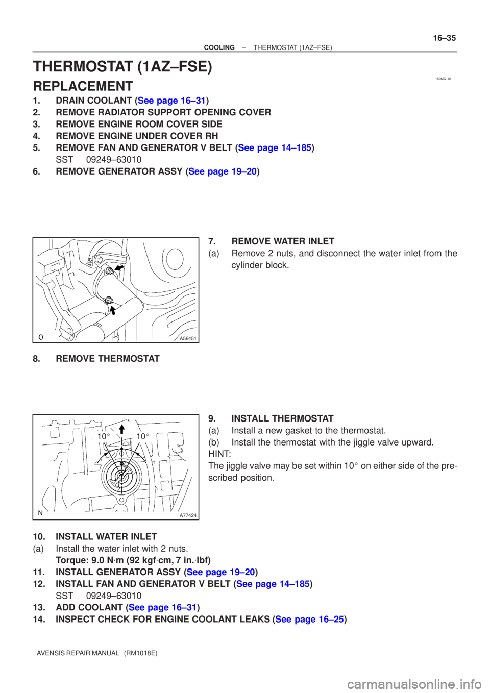
(a)Remove 2 nuts, and disconnect the water inlet from thecylinder block.
8.REMOVE THERMOSTAT 9.INSTALL THERMOSTAT
(a)Install a new gasket to the thermostat.
(b)Install the thermostat with the jiggle valve upward.
HINT:
The jiggle valve may be set within 10� on either side of the pre-
scribed position.
10.INSTALL WATER INLET
(a)Install the water inlet with 2 nuts. Torque: 9.0 N �m (92 kgf �cm,7 in. �lbf)
11.INSTALL GENERATOR ASSY (See page 19±20)
12.INSTALL FAN AND GENERATOR V BELT (See page 14±185) SST 09249±63010
13.ADD COOLANT (See page 16±31)
14.INSPECT CHECK FOR ENGINE COOLANT LEAKS(See page 16±25)
Page 177 of 1690
160MJ±01
A62118
10�10�
16±10
±
COOLING THERMOSTAT(1ZZ±FE/3ZZ±FE)
AVENSIS REPAIR MANUAL (RM1018E)
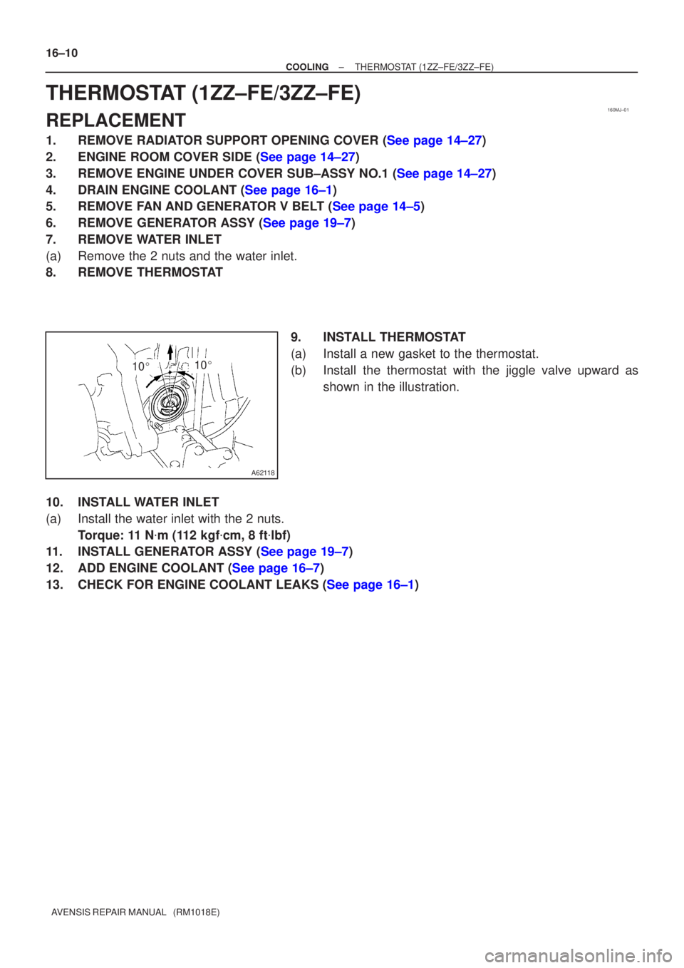
THERMOSTAT(1ZZ±FE/3ZZ±FE)
REPLACEMENT
1.REMOVE RADIATOR SUPPORT OPENING COVER (See page 14±27)
2.ENGINE ROOM COVER SIDE (See page 14±27)
3.REMOVE ENGINE UNDER COVER SUB±ASSY NO.1 (See page 14±27)
4.DRAIN ENGINE COOLANT (See page 16±1)
5.REMOVE FAN AND GENERATOR V BELT (See page 14±5)
6.REMOVE GENERATOR ASSY (See page 19±7)
7.REMOVE WATER INLET
(a)Remove the 2 nuts and the water inlet.
8.REMOVE THERMOSTAT 9.INSTALL THERMOSTAT
(a)Install a new gasket to the thermostat.
(b)Install the thermostat with the jiggle valve upward asshown in the illustration.
10.INSTALL WATER INLET
(a)Install the water inlet with the 2 nuts. Torque: 11 N �m (112 kgf �cm, 8 ft �lbf)
11.INSTALL GENERATOR ASSY (See page 19±7)
12.ADD ENGINE COOLANT (See page 16±7)
13.CHECK FOR ENGINE COOLANT LEAKS (See page 16±1)