Page 338 of 1690
141BK±01
A77281
A77283
A77284
± ENGINE MECHANICALCAMSHAFT (1AZ±FE)
14±171
AVENSIS REPAIR MANUAL (RM1018E)
REPLACEMENT
1. REMOVE RADIATOR SUPPORT OPENING COVER
2. REMOVE ENGINE ROOM COVER SIDE
3. REMOVE ENGINE UNDER COVER RH
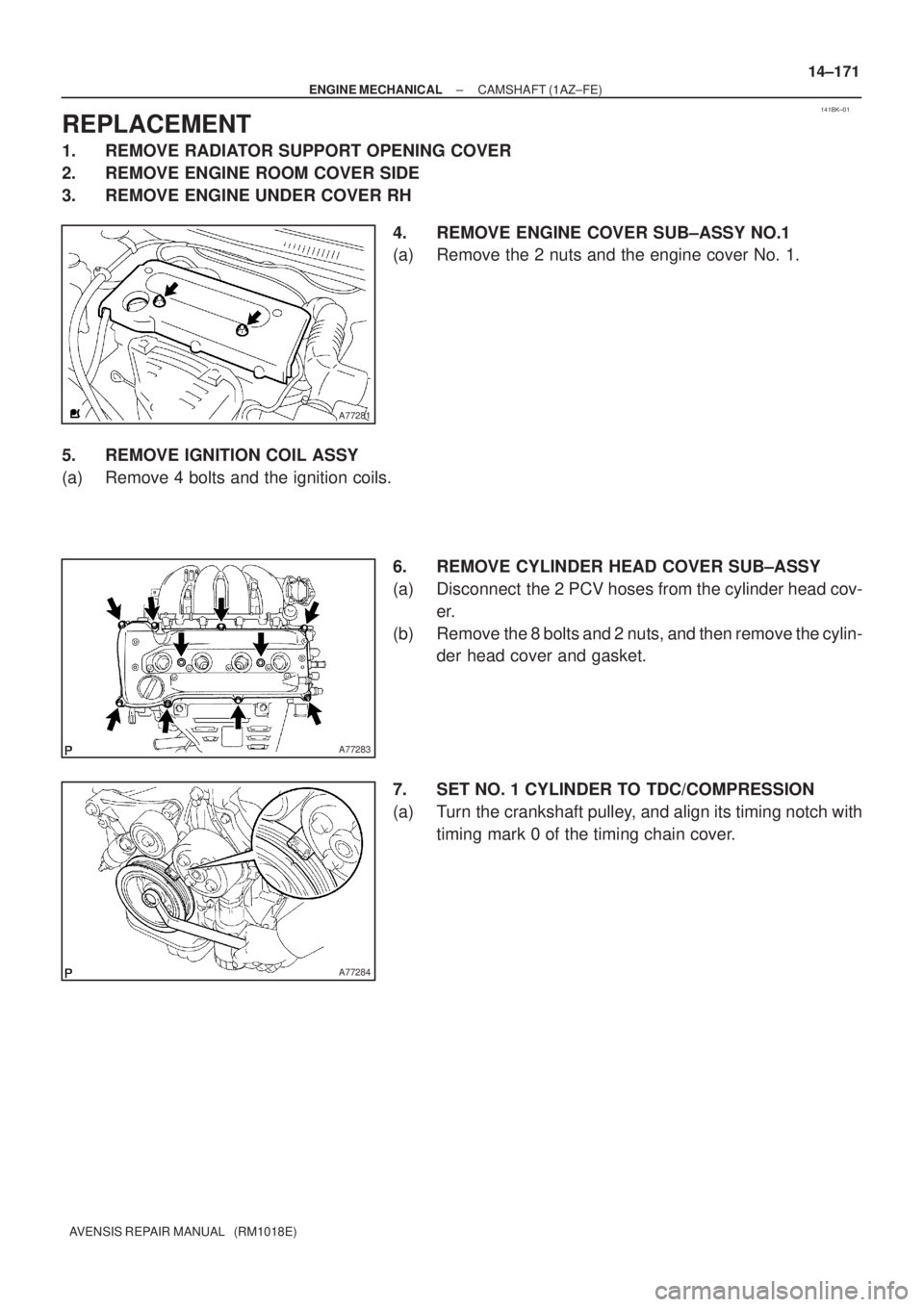
4. REMOVE ENGINE COVER SUB±ASSY NO.1
(a) Remove the 2 nuts and the engine cover No. 1.
5. REMOVE IGNITION COIL ASSY
(a) Remove 4 bolts and the ignition coils.
6. REMOVE CYLINDER HEAD COVER SUB±ASSY
(a) Disconnect the 2 PCV hoses from the cylinder head cov-
er.
(b) Remove the 8 bolts and 2 nuts, and then remove the cylin-
der head cover and gasket.
7. SET NO. 1 CYLINDER TO TDC/COMPRESSION
(a) Turn the crankshaft pulley, and align its timing notch with
timing mark 0 of the timing chain cover.
Page 341 of 1690
A31032
A32639
A77414
Straight
Pin
Key
Groove 14±174
± ENGINE MECHANICALCAMSHAFT (1AZ±FE)
AVENSIS REPAIR MANUAL (RM1018E)
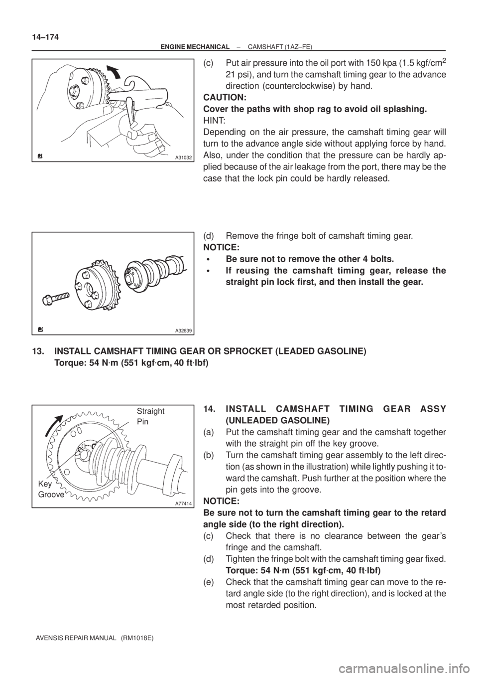
(c) Put air pressure into the oil port with 150 kpa (1.5 kgf/cm2
21 psi), and turn the camshaft timing gear to the advance
direction (counterclockwise) by hand.
CAUTION:
Cover the paths with shop rag to avoid oil splashing.
HINT:
Depending on the air pressure, the camshaft timing gear will
turn to the advance angle side without applying force by hand.
Also, under the condition that the pressure can be hardly ap-
plied because of the air leakage from the port, there may be the
case that the lock pin could be hardly released.
(d) Remove the fringe bolt of camshaft timing gear.
NOTICE:
�Be sure not to remove the other 4 bolts.
�If reusing the camshaft timing gear, release the
straight pin lock first, and then install the gear.
13. INSTALL CAMSHAFT TIMING GEAR OR SPROCKET (LEADED GASOLINE)
Torque: 54 N�m (551 kgf�cm, 40 ft�lbf)
14. INSTALL CAMSHAFT TIMING GEAR ASSY
(UNLEADED GASOLINE)
(a) Put the camshaft timing gear and the camshaft together
with the straight pin off the key groove.
(b) Turn the camshaft timing gear assembly to the left direc-
tion (as shown in the illustration) while lightly pushing it to-
ward the camshaft. Push further at the position where the
pin gets into the groove.
NOTICE:
Be sure not to turn the camshaft timing gear to the retard
angle side (to the right direction).
(c) Check that there is no clearance between the gear's
fringe and the camshaft.
(d) Tighten the fringe bolt with the camshaft timing gear fixed.
Torque: 54 N�m (551 kgf�cm, 40 ft�lbf)
(e) Check that the camshaft timing gear can move to the re-
tard angle side (to the right direction), and is locked at the
most retarded position.
Page 345 of 1690
141BP±01
A77322
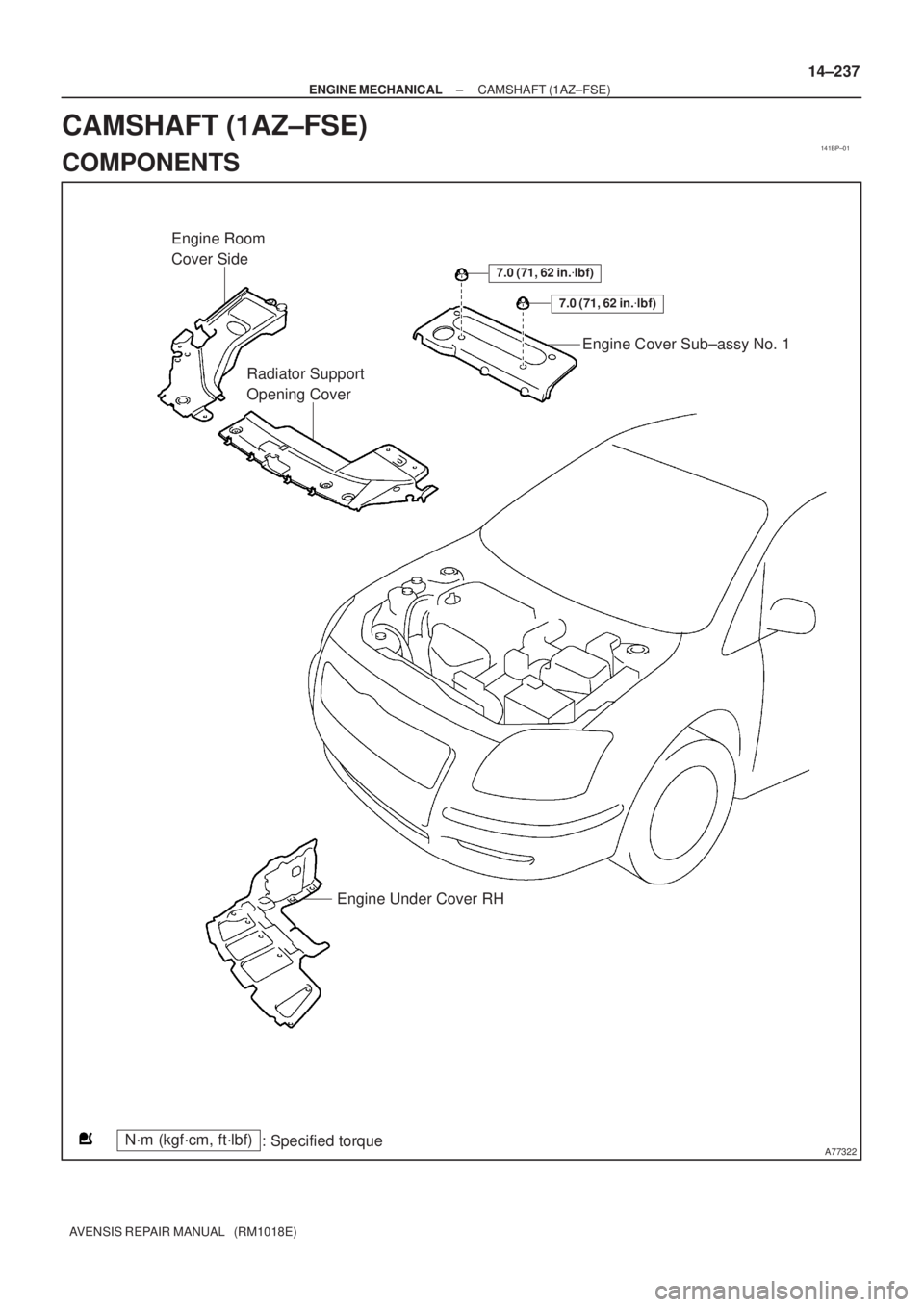
7.0 (71, 62 in.�lbf)
7.0 (71, 62 in.�lbf)
Engine Room
Cover Side
Radiator Support
Opening CoverEngine Cover Sub±assy No. 1
Engine Under Cover RH
N´m (kgf´cm, ft´lbf)
: Specified torque
± ENGINE MECHANICALCAMSHAFT (1AZ±FSE)
14±237
AVENSIS REPAIR MANUAL (RM1018E)
CAMSHAFT (1AZ±FSE)
COMPONENTS
Page 348 of 1690
141BQ±01
A77339
A77284
14±240
±
ENGINE MECHANICAL CAMSHAFT(1AZ±FSE)
AVENSIS REPAIR MANUAL (RM1018E)
REPLACEMENT
1.DISCHARGE FUEL SYSTEM PRESSURE (See page 11±30)
2.REMOVE RADIATOR SUPPORT OPENING COVER
3.REMOVE ENGINE ROOM COVER SIDE
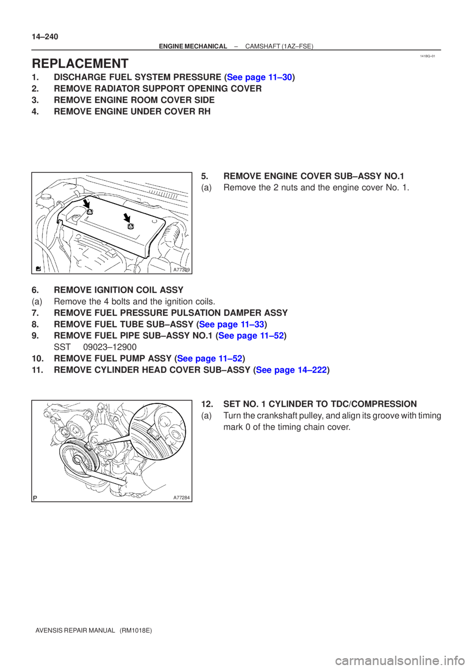
4.REMOVE ENGINE UNDER COVER RH 5.REMOVE ENGINE COVER SUB±ASSY NO.1
(a)Remove the 2 nuts and the engine cover No. 1.
6.REMOVE IGNITION COIL ASSY
(a)Remove the 4 bolts and the ignition coils.
7.REMOVE FUEL PRESSURE PULSATION DAMPER ASSY
8.REMOVE FUEL TUBE SUB±ASSY (See page 11±33)
9.REMOVE FUEL PIPE SUB±ASSY NO.1 (See page 11±52) SST 09023±12900
10.REMOVE FUEL PUMP ASSY (See page 11±52)
11.REMOVE CYLINDER HEAD COVER SUB±ASSY (See page 14±222)
12. SET NO. 1 CYLINDER TO TDC/COMPRESSION
(a) Turn the crankshaft pulley, and align its groove with timingmark 0 of the timing chain cover.
Page 350 of 1690
A77309
15973
481062
A56228
A77413
Advance
Side Port
A31032
14±242
± ENGINE MECHANICALCAMSHAFT (1AZ±FSE)
AVENSIS REPAIR MANUAL (RM1018E)
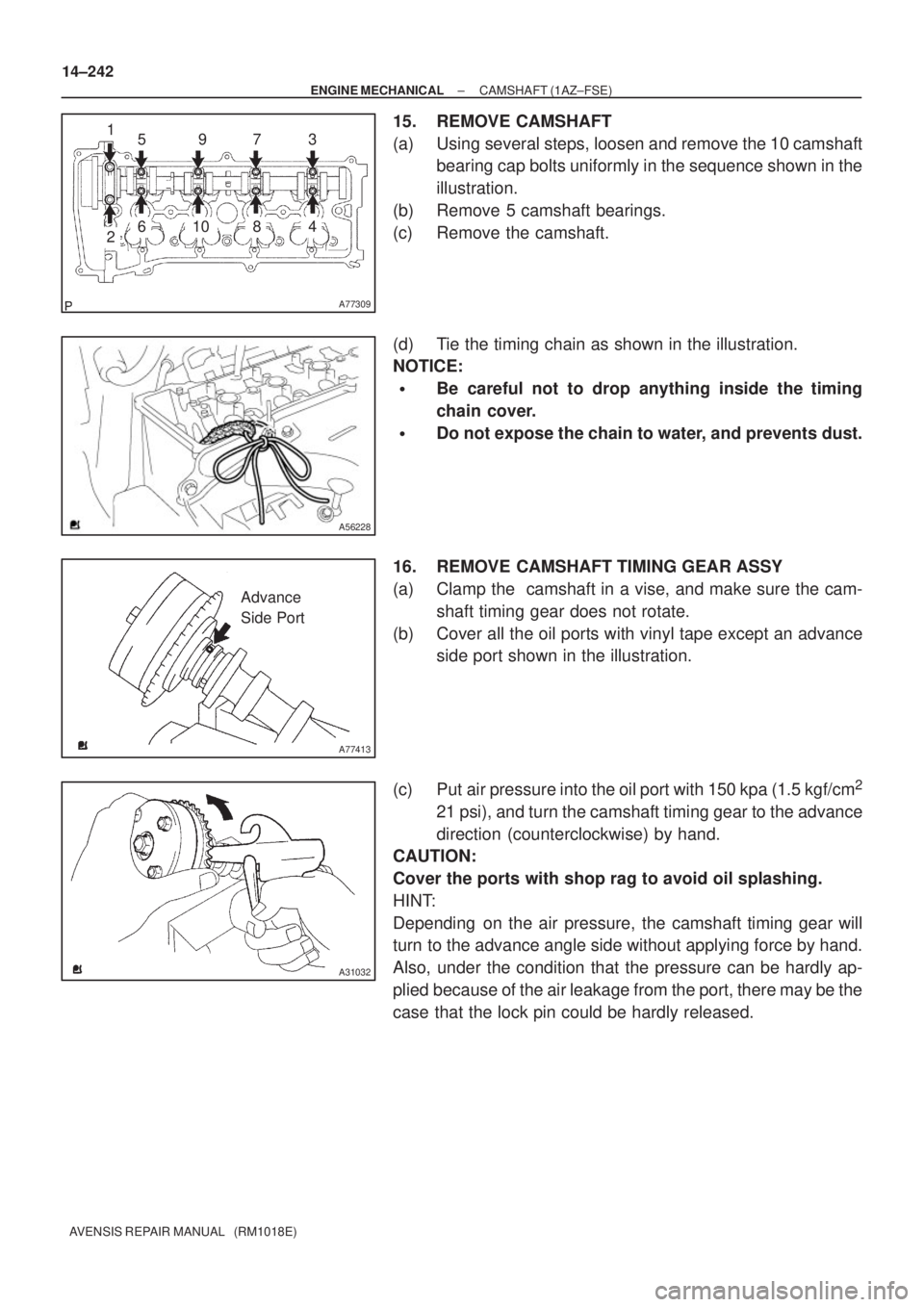
15. REMOVE CAMSHAFT
(a) Using several steps, loosen and remove the 10 camshaft
bearing cap bolts uniformly in the sequence shown in the
illustration.
(b) Remove 5 camshaft bearings.
(c) Remove the camshaft.
(d) Tie the timing chain as shown in the illustration.
NOTICE:
�Be careful not to drop anything inside the timing
chain cover.
�Do not expose the chain to water, and prevents dust.
16. REMOVE CAMSHAFT TIMING GEAR ASSY
(a) Clamp the camshaft in a vise, and make sure the cam-
shaft timing gear does not rotate.
(b) Cover all the oil ports with vinyl tape except an advance
side port shown in the illustration.
(c) Put air pressure into the oil port with 150 kpa (1.5 kgf/cm
2
21 psi), and turn the camshaft timing gear to the advance
direction (counterclockwise) by hand.
CAUTION:
Cover the ports with shop rag to avoid oil splashing.
HINT:
Depending on the air pressure, the camshaft timing gear will
turn to the advance angle side without applying force by hand.
Also, under the condition that the pressure can be hardly ap-
plied because of the air leakage from the port, there may be the
case that the lock pin could be hardly released.
Page 354 of 1690
141C7±01
A79426N´m (kgf´cm, ft´lbf)
: Specified torque
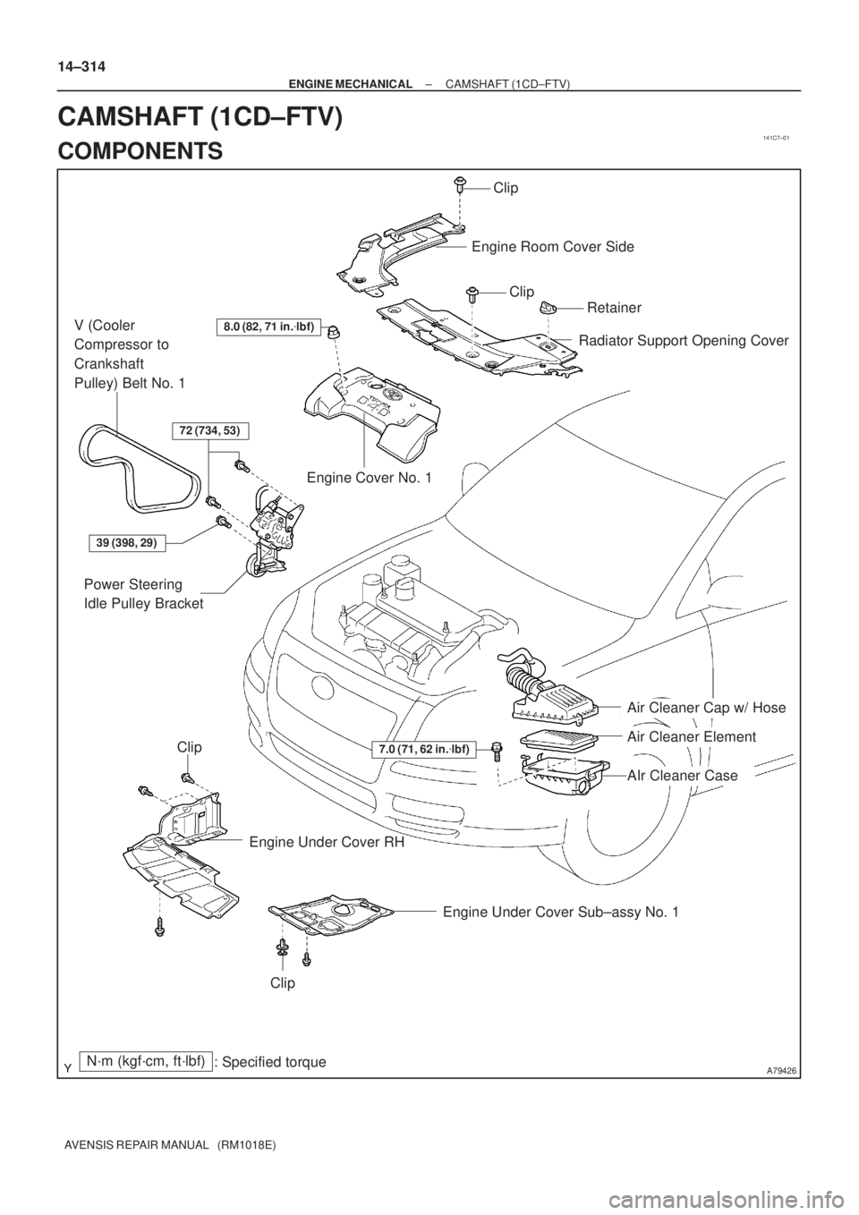
8.0 (82, 71 in.�lbf)
7.0 (71, 62 in.�lbf)
39 (398, 29)
72 (734, 53)
Engine Cover No. 1Engine Room Cover Side
Radiator Support Opening Cover
Power Steering
Idle Pulley Bracket
Engine Under Cover Sub±assy No. 1
Air Cleaner Cap w/ Hose
Air Cleaner Element
AIr Cleaner Case
Engine Under Cover RH
V (Cooler
Compressor to
Crankshaft
Pulley) Belt No. 1Clip
Clip
Retainer
Clip
Clip
14±314
± ENGINE MECHANICALCAMSHAFT (1CD±FTV)
AVENSIS REPAIR MANUAL (RM1018E)
CAMSHAFT (1CD±FTV)
COMPONENTS
Page 358 of 1690
141C8±01
SSTA61187
14±318
±
ENGINE MECHANICAL CAMSHAFT(1CD±FTV)
AVENSIS REPAIR MANUAL (RM1018E)
REPLACEMENT
1.REMOVE FRONT WHEEL RH
2.REMOVE ENGINE UNDER COVER SUB±ASSY NO.1
3.ENGINE UNDER COVER RH
4.REMOVE RADIATOR SUPPORT OPENING COVER
5.REMOVE ENGINE ROOM COVER SIDE
6.REMOVE ENGINE COVER NO.1
(a)Remove the 5 nuts and the engine cover.
7.REMOVE AIR CLEANER ASSY (See page 11±60)
8.REMOVE VACUUM RESERVOIR SUB±ASSY
(a)Disconnect the 2 vacuum hoses and the connector.
(b)Remove the 2 bolts and the vacuum reservoir.
9.REMOVE AIR TUBE NO.1 (See page 14±270)
10.REMOVE INJECTOR DRIVER (See page 14±286)
11. REMOVE V (COOLER COMPRESSOR TO CRANKSHAFT PULLEY) BELT NO.1 (See page 14±269)
12.REMOVE GENERATOR V BELT (See page 14±269)
13.SEPARATE POWER STEERING IDLE PULLEY BRACKET (See page 14±286)
14.REMOVE ENGINE MOUNTING INSULATOR SUB±ASSY RH (See page 14±307)
15.REMOVE CRANKSHAFT PULLEY (See page 14±307) SST 09213±54015 (90105±08076), 09330±00021, 09950±50013 (0995\
1±05010, 09952±05010, 09953±05020, 09954±05031)
16.REMOVE IDLER PULLEY SUB±ASSY (See page 14±307)
17.REMOVE TIMING BELT NO.2 COVER (See page 14±307)
18.REMOVE TIMING BELT NO.1 COVER (See page 14±307)
19. REMOVE TIMING BELT GUIDE
20.REMOVE TRANSVERSE ENGINE ENGINE MOUNTING BRACKET (See page 14±307)
21.SET NO. 1 CYLINDER TO TDC/COMPRESSION (See page 14±307)
22.REMOVE TIMING CHAIN COVER PLATE (See page 14±307)
23.REMOVE TIMING BELT (See page 14±307)
24.REMOVE CAMSHAFT POSITION SENSOR (See page 10±63)
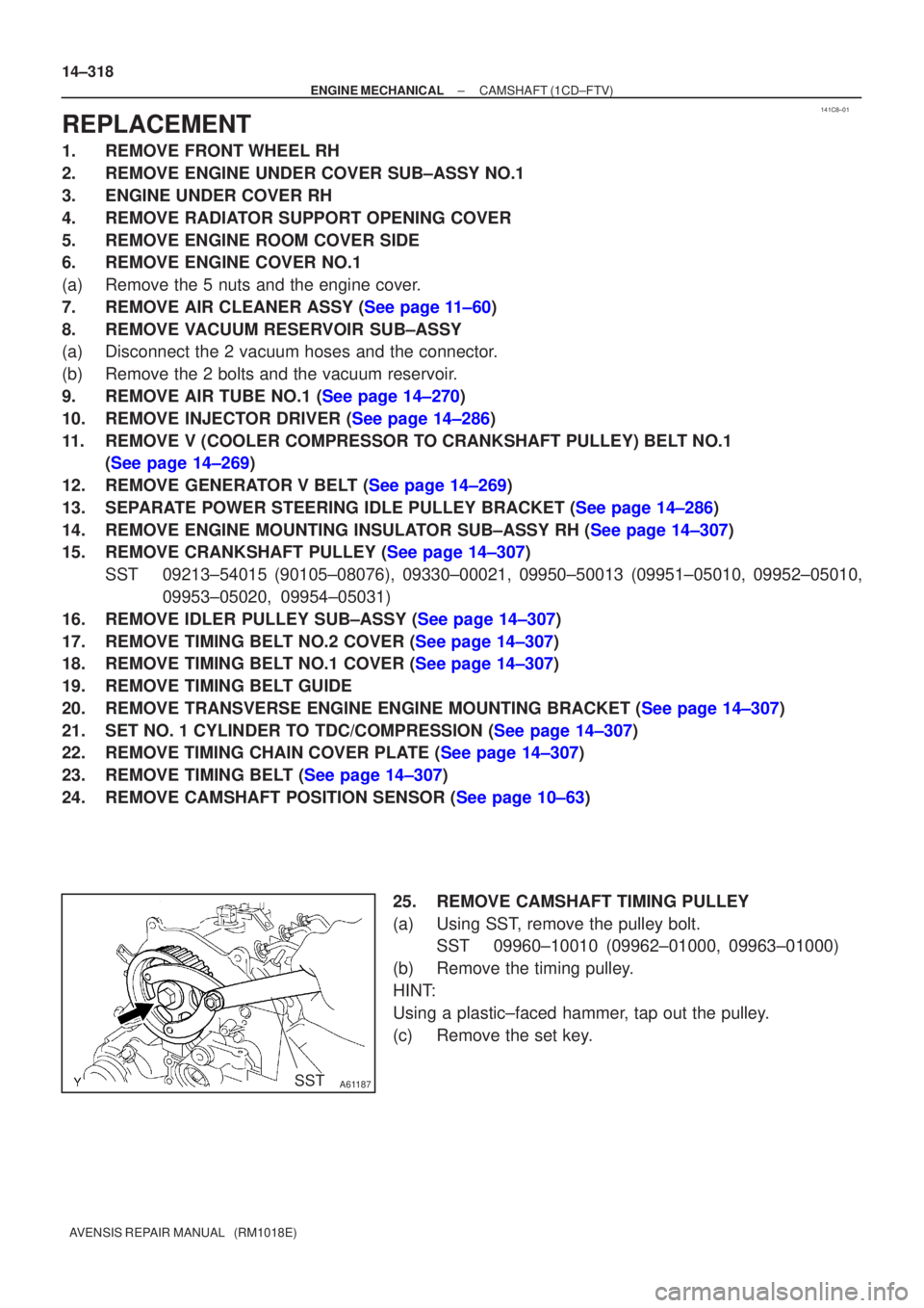
25. REMOVE CAMSHAFT TIMING PULLEY
(a) Using SST, remove the pulley bolt.SST 09960±10010 (09962±01000, 09963±01000)
(b) Remove the timing pulley.
HINT:
Using a plastic±faced hammer, tap out the pulley.
(c) Remove the set key.
Page 363 of 1690
A62592
SST
A09663
:Seal Packing
±
ENGINE MECHANICAL CAMSHAFT(1CD±FTV)
14±323
AVENSIS REPAIR MANUAL (RM1018E)
(c)Install the oil seal retainer with the 4 bolts. Tighten the 4
bolts uniformly in several steps.
Torque: 8.8 N �m (90 kgf �cm, 78 in. �lbf)
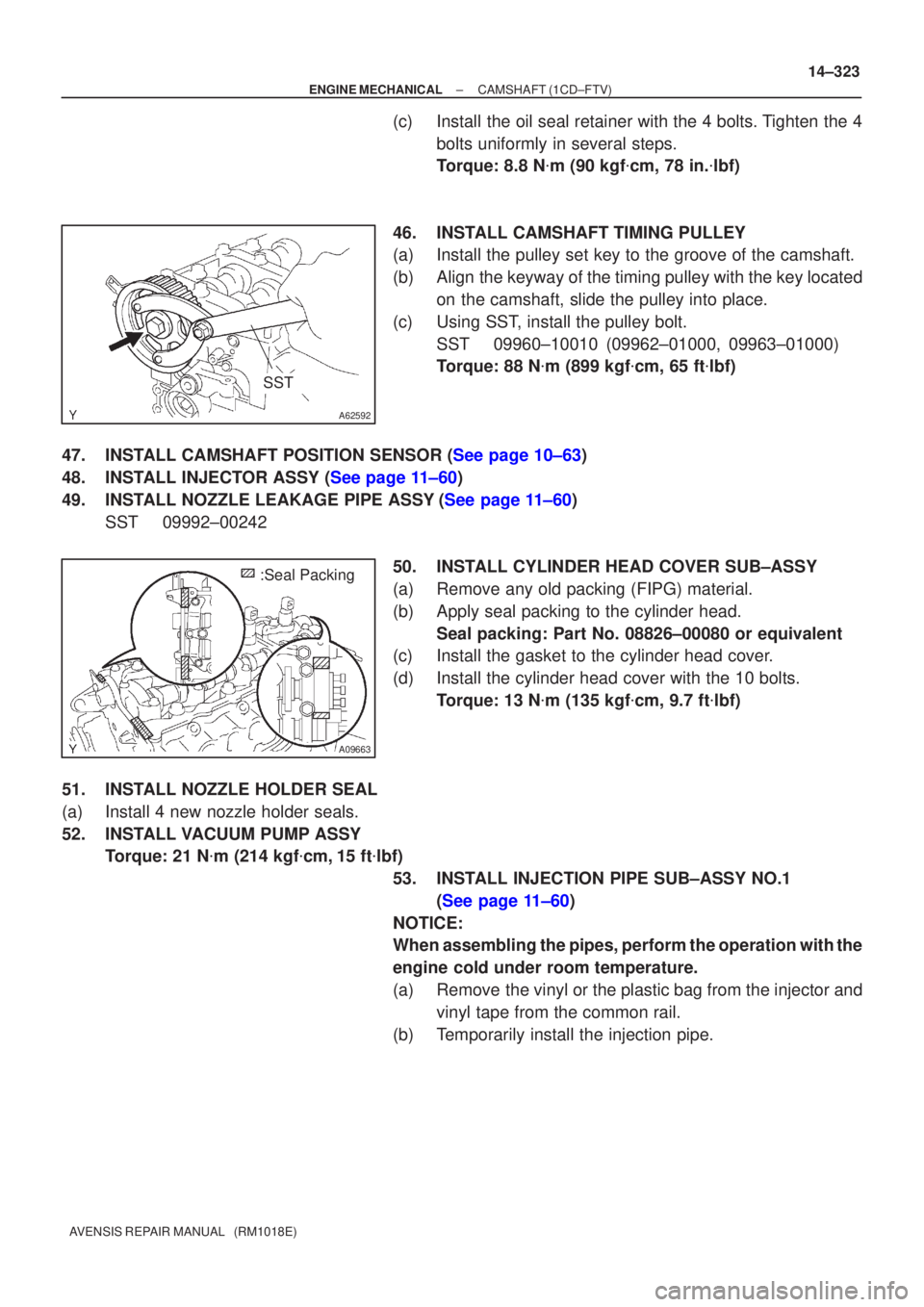
46.INSTALL CAMSHAFT TIMING PULLEY
(a)Install the pulley set key to the groove of the camshaft.
(b)Align the keyway of the timing pulley with the key located on the camshaft, slide the pulley into place.
(c)Using SST, install the pulley bolt. SST09960±10010 (09962±01000, 09963±01000)
Torque: 88 N �m (899 kgf �cm, 65 ft �lbf)
47.INSTALL CAMSHAFT POSITION SENSOR (See page 10±63)
48.INSTALL INJECTOR ASSY (See page 11±60)
49.INSTALL NOZZLE LEAKAGE PIPE ASSY(See page 11±60) SST09992±00242
50.INSTALL CYLINDER HEAD COVER SUB±ASSY
(a)Remove any old packing (FIPG) material.
(b)Apply seal packing to the cylinder head.Seal packing: Part No. 08826±00080 or equivalent
(c)Install the gasket to the cylinder head cover.
(d)Install the cylinder head cover with the 10 bolts.
Torque: 13 N �m (135 kgf �cm, 9.7 ft �lbf)
51.INSTALL NOZZLE HOLDER SEAL
(a)Install 4 new nozzle holder seals.
52.INSTALL VACUUM PUMP ASSY Torque: 21 N �m (214 kgf �cm,15 ft �lbf)
53.INSTALL INJECTION PIPE SUB±ASSY NO.1 (See page 11±60)
NOTICE:
When assembling the pipes, perform the operation with the
engine cold under room temperature.
(a) Remove the vinyl or the plastic bag from the injector and vinyl tape from the common rail.
(b) Temporarily install the injection pipe.