Page 13 of 1690
670S5±01
I35223
Instrument Cluster Finish Panel Garnish No.2
Radio Bracket No.2Radio Receiver Assy
Instrument Panel
Register Assy CTR
Air Conditioning Control AssyConsole Panel
Sub±assy Upper
Navigation System:Navigation Computer Cover
Instrument Panel
Support No.3 Instrument Panel
Support No.1Instrument Panel
Support No.2
Door Control Motor
Door Control Switch
Assy (TILT)
Instrument Cluster Finish Panel AssyDoor Control Switch Instrument Cluster Finish
Upper PanelMulti±display Instrument Panel Box
Door CoverRadio Bracket No.1
Instrument Panel
Register Control Gear
Control Knob
Protector No.1
Position Sensor
67±2
± AUDIO & VISUAL SYSTEMAUDIO & VISUAL SYSTEM
AVENSIS REPAIR MANUAL (RM1018E)
COMPONENTS
Page 29 of 1690
670S6±02
I35191
I35165
I35166
±
AUDIO & VISUAL SYSTEM RADIO RECEIVER ASSY
67±5
AVENSIS REPAIR MANUAL (RM1018E)
RADIO RECEIVER ASSY
REPLACEMENT
1.DISCONNECT BATTERY NEGATIVE TERMINAL (See page 60±1)
2.REMOVE INSTRUMENT CLUSTER FINISH PANEL GARNISH NO.2 (See page 71±11)
3.REMOVE INSTRUMENT PANEL REGISTER ASSY CTR (See page 71±11)
4.REMOVE CONSOLE PANEL SUB±ASSY UPPER (See page 71±11)
5.REMOVE RADIO RECEIVER ASSEMBLYW/BRACKET
(a)Remove the 4 bolts.
(b)Disconnect the connector and remove the radio receiver assy w/ bracket.
6.REMOVE RADIO BRACKET NO.1
(a)Remove the 6 screws and radio bracket No.1.
7.REMOVE RADIO BRACKET NO.2
(a)Remove the 6 screws and radio bracket No.2.
8.REMOVE AIR CONDITIONING CONTROL ASSY (See page 55±50)
9. REMOVE RADIO RECEIVER ASSY
Page 84 of 1690

G23168
F08658
SST
G23167
32±62
±
BRAKE SKID CONTROL SENSOR
AVENSIS REPAIR MANUAL (RM1018E)
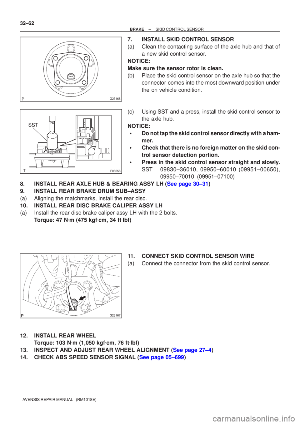
7. INSTALL SKID CONTROL SENSOR
(a) Clean the contacting surface of the axle hub and that of a new skid control sensor.
NOTICE:
Make sure the sensor rotor is clean.
(b) Place the skid control sensor on the axle hub so that the connector comes into the most downward position under
the on vehicle condition.
(c) Using SST and a press, install the skid control sensor to the axle hub.
NOTICE:
�Do not tap the skid control sensor directly with a ham-
mer.
�Check that there is no foreign matter on the skid con-
trol sensor detection portion.
�Press in the skid control sensor straight and slowly.
SST 09830±36010, 09950±60010 (09951±00650), 09950±70010 (09951±07100)
8.INSTALL REAR AXLE HUB & BEARING ASSY LH (See page 30±31)
9. INSTALL REAR BRAKE DRUM SUB±ASSY
(a) Aligning the matchmarks, install the rear disc.
10. INSTALL REAR DISC BRAKE CALIPER ASSY LH
(a) Install the rear disc brake caliper assy LH with the 2 bolts. Torque: 47 N �m (475 kgf �cm, 34 ft �lbf)
11. CONNECT SKID CONTROL SENSOR WIRE
(a) Connect the connector from the skid control sensor.
12. INSTALL REAR WHEEL Torque: 103 N �m (1,050 kgf �cm, 76 ft �lbf)
13.INSPECT AND ADJUST REAR WHEEL ALIGNMENT (See page 27±4)
14.CHECK ABS SPEED SENSOR SIGNAL (See page 05±699)
Page 133 of 1690
69066±02
B67416
B67417
B68374
21
5
3
± COMMUNICATION SYSTEMHORN SYSTEM
69±3
AVENSIS REPAIR MANUAL (RM1018E)
INSPECTION
1. INSPECT LOW PITCHED HORN ASSY
(a) Check operation of the horn.
Standard:
Measurement ConditionSpecified Condition
Battery positive (+) �Terminal 1
Battery positive (±) �Horn bodyHorn sounds
If the result is not as specified, replace the horn assy.
2. INSPECT HIGH PITCHED HORN ASSY
(a) Check operation of the horn.
Standard:
Measurement ConditionSpecified Condition
Battery positive (+) �Terminal 1
Battery positive (±) �Horn bodyHorn sounds
If the result is not as specified, replace the horn assy.
3. INSPECT HORN RELAY ASSY
(a) Remove the HORN relay from the engine room R/B No.
2.
(b) Check the horn relay resistance.
Standard:
Tester ConnectionSpecified Condition
10 k� or higher
3 ± 5Below 1 �
(When battery voltage is applied to terminals 1 and 2)
If the result is not as specified, replace the relay assy.
Page 135 of 1690

1600R±13
± COOLINGCOOLING FAN SYSTEM (1AZ±FE)
16±17
AVENSIS REPAIR MANUAL (RM1018E)
COOLING FAN SYSTEM (1AZ±FE)
ON±VEHICLE INSPECTION
HINT:
It is normal that the cooling fan sometime rotates when the ignition switch is turned from ACC to ON.
1. CHECK COOLING FAN OPERATION WITH LOW TEMPERATURE (Below 77�C (171�F))
(a) Turn the ignition switch ON.
(b) Check that the cooling fan stops.
If not, check the cooling fan relay and engine coolant temperature sensor, and check for disconnection of
connectors or wire break between the cooling fan relay and engine coolant temperature sensor.
(c) Disconnect the engine coolant temperature sensor connector.
(d) Check that the cooling fan rotates.
If not, check the fuses, cooling fan relay, ECM and cooling fan, and check for a short circuit between the
cooling fan relay and engine coolant temperature sensor.
(e) Reconnect the engine coolant temperature sensor connector.
2. CHECK COOLING FAN OPERATION WITH HIGH TEMPERATURE (Above 95.5�C (204�F))
(a) Start the engine, and raise coolant temperature to above 95.5�C (204�F).
HINT:
Coolant temperature is the detected value by the engine coolant temperature sensor on the water outlet.
(b) Check that the cooling fan rotates.
If not, replace the engine coolant temperature sensor.
3. INSPECT COOLING FAN
(a) Disconnect the cooling fan connector.
(b) Connect battery and ammeter to the cooling fan connector.
(c) Check that the cooling fan rotates smoothly, and check the reading on the ammeter.
Standard amperage:
5.2 to 8.2 A at 20�C (68�F) (M/T)
8.3 to 11.3 A at 20�C (68�F) (A/T)
(d) Reconnect the cooling fan connector.
4. INSPECT COOLING FAN No.2 (With Air Conditioner)
(a) Disconnect the cooling fan connector.
(b) Connect battery and ammeter to the cooling fan connector.
(c) Check that the cooling fan rotates smoothly, and check the reading on the ammeter.
Standard amperage:
5.2 to 8.2 A at 20�C (68�F) (M/T)
8.3 to 11.3 A at 20�C (68�F) (A/T)
(d) Reconnect the cooling fan connector.
Page 136 of 1690
160N3±01
E34090
A30519
E34090
16±18
± COOLINGCOOLING FAN SYSTEM (1AZ±FE)
AVENSIS REPAIR MANUAL (RM1018E)
INSPECTION
1. INSPECT COOLING FAN RELAY
(a) Continuity inspection.
(1) Using an ohmmeter, check for continuity between
each terminal.
Specified condition:
Terminal No.Specified condition
1 ± 2Continuity
No continuity
3 ± 5Continuity
(Apply battery voltage terminals 1 and 2)
2. INSPECT COOLING FAN RELAY NO.2
(a) Continuity inspection.
(1) Using an ohmmeter, check for continuity between
each terminal.
Specified condition:
Terminal No.Specified condition
1 ± 2
3 ± 4Continuity
No continuity
3 ± 5Continuity
(Apply battery voltage terminals 1 and 2)
3. INSPECT COOLING FAN RELAY NO.3
(a) Continuity inspection.
(1) Using an ohmmeter, check for continuity between
each terminal.
Specified condition:
Terminal No.Specified condition
1 ± 2Continuity
No continuity
3 ± 5Continuity
(Apply battery voltage terminals 1 and 2)
Page 137 of 1690

1600R±12
± COOLINGCOOLING FAN SYSTEM (1AZ±FSE)
16±29
AVENSIS REPAIR MANUAL (RM1018E)
COOLING FAN SYSTEM (1AZ±FSE)
ON±VEHICLE INSPECTION
HINT:
It is normal that the cooling fan sometime rotates when the ignition switch is turned from ACC to ON.
1. CHECK COOLING FAN OPERATION WITH LOW TEMPERATURE (Below 83�C (181�F))
(a) Turn the ignition switch ON.
(b) Check that the cooling fan stops.
If not, check the cooling fan relay and engine coolant temperature sensor, and check for disconnection of
connectors or wire break between the cooling fan relay and engine coolant temperature sensor.
(c) Disconnect the engine coolant temperature sensor connector.
(d) Check that the cooling fan rotates.
If not, check the fuses, cooling fan relay, ECM and cooling fan, and check for a short circuit between the
cooling fan relay and engine coolant temperature sensor.
(e) Reconnect the engine coolant temperature sensor connector.
2. CHECK COOLING FAN OPERATION WITH HIGH TEMPERATURE (Above 100�C (212�F))
(a) Start the engine, and raise coolant temperature to above 100�C (212�F).
HINT:
Coolant temperature is the detected value by the engine coolant temperature sensor on the water outlet.
(b) Check that the cooling fan rotates.
If not, replace the engine coolant temperature sensor.
3. INSPECT COOLING FAN
(a) Disconnect the cooling fan connector.
(b) Connect battery and ammeter to the cooling fan connector.
(c) Check that the cooling fan rotates smoothly, and check the reading on the ammeter.
Standard amperage:
5.2 to 8.2 A at 20�C (68�F) (M/T)
8.3 to 11.3 A at 20�C (68�F) (A/T)
(d) Reconnect the cooling fan connector.
4. INSPECT COOLING FAN No.2 (With Air Conditioner)
(a) Disconnect the cooling fan connector.
(b) Connect battery and ammeter to the cooling fan connector.
(c) Check that the cooling fan rotates smoothly, and check the reading on the ammeter.
Standard amperage:
5.2 to 8.2 A at 20�C (68�F) (M/T)
8.3 to 11.3 A at 20�C (68�F) (A/T)
(d) Reconnect the cooling fan connector.
Page 138 of 1690
160N0±01
E34090
A30519
E34090
16±30
± COOLINGCOOLING FAN SYSTEM (1AZ±FSE)
AVENSIS REPAIR MANUAL (RM1018E)
INSPECTION
1. INSPECT COOLING FAN RELAY
(a) Continuity inspection.
(1) Using an ohmmeter, check for continuity between
each terminal.
Specified condition:
Terminal No.Specified condition
1 ± 2Continuity
No continuity
3 ± 5Continuity
(Apply battery boltage terminals 1 and 2)
2. INSPECT COOLING FAN RELAY NO.2
(a) Continuity inspection.
(1) Using an ohmmeter, check for continuity between
each terminal.
Specified condition:
Terminal No.Specified condition
1 ± 2
3 ± 4Continuity
No continuity
3 ± 5Continuity
(Apply battery boltage terminals 1 and 2)
3. INSPECT COOLING FAN RELAY NO.3
(a) Continuity inspection.
(1) Using an ohmmeter, check for continuity between
each terminal.
Specified condition:
Terminal No.Specified condition
1 ± 2Continuity
No continuity
3 ± 5Continuity
(Apply battery boltage terminals 1 and 2)