Page 62 of 1690

320VI±01
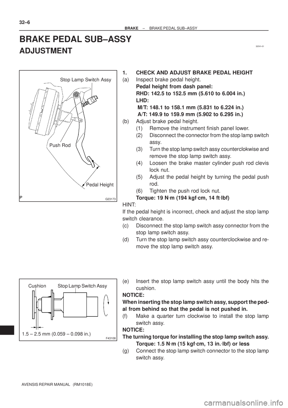
G23173
Stop Lamp Switch Assy
Push Rod
Pedal Height
F43108
Stop Lamp Switch Assy Cushion
1.5 ± 2.5 mm (0.059 ± 0.098 in.) 32±6
± BRAKEBRAKE PEDAL SUB±ASSY
AVENSIS REPAIR MANUAL (RM1018E)
BRAKE PEDAL SUB±ASSY
ADJUSTMENT
1. CHECK AND ADJUST BRAKE PEDAL HEIGHT
(a) Inspect brake pedal height.
Pedal height from dash panel:
RHD: 142.5 to 152.5 mm (5.610 to 6.004 in.)
LHD:
M/T: 148.1 to 158.1 mm (5.831 to 6.224 in.)
A/T: 149.9 to 159.9 mm (5.902 to 6.295 in.)
(b) Adjust brake pedal height.
(1) Remove the instrument finish panel lower.
(2) Disconnect the connector from the stop lamp switch
assy.
(3) Turn the stop lamp switch assy counterclokwise and
remove the stop lamp switch assy.
(4) Loosen the brake master cylinder push rod clevis
lock nut.
(5) Adjust the pedal height by turning the pedal push
rod.
(6) Tighten the push rod lock nut.
Torque: 19 N�m (194 kgf�cm, 14 ft�lbf)
HINT:
If the pedal height is incorrect, check and adjust the stop lamp
switch clearance.
(c) Disconnect the stop lamp switch assy connector from the
stop lamp switch assy.
(d) Turn the stop lamp switch assy counterclockwise and re-
move the stop lamp switch assy.
(e) Insert the stop lamp switch assy until the body hits the
cushion.
NOTICE:
When inserting the stop lamp switch assy, support the ped-
al from behind so that the pedal is not pushed in.
(f) Make a quarter turn clockwise to install the stop lamp
switch assy.
NOTICE:
The turning torque for installing the stop lamp switch assy.
Torque: 1.5 N�m (15 kgf�cm, 13 in.�lbf) or less
(g) Connect the stop lamp switch connector to the stop lamp
switch assy.
Page 68 of 1690

3201B±12
32±2
±
BRAKE BRAKE SYSTEM
AVENSIS REPAIR MANUAL (RM1018E)
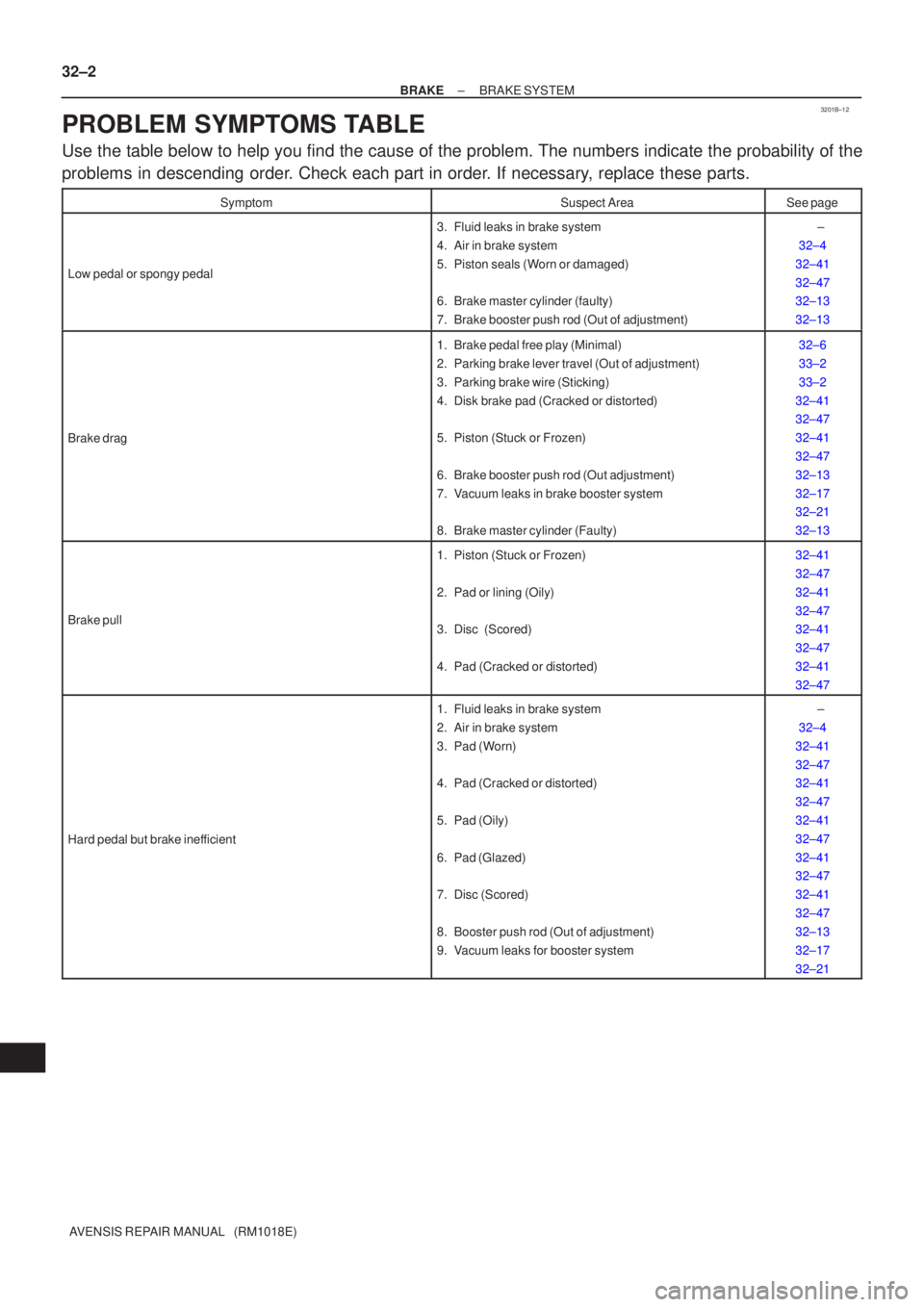
PROBLEM SYMPTOMS TABLE
Use the table below to help you find the cause of the problem. The numbers \
indicate the probability of the
problems in descending order. Check each part in order. If necessary, replace these parts.
SymptomSuspect AreaSee page
Low pedal or spongy pedal
3. Fluid leaks in brake system
4. Air in brake system
5. Piston seals (Worn or damaged)
6. Brake master cylinder (faulty)
7. Brake booster push rod (Out of adjustment) ±
32±4
32±41
32±47
32±13
32±13
Brake drag
1. Brake pedal free play (Minimal)
2. Parking brake lever travel (Out of adjustment)
3. Parking brake wire (Sticking)
4. Disk brake pad (Cracked or distorted)
5. Piston (Stuck or Frozen)
6. Brake booster push rod (Out adjustment)
7. Vacuum leaks in brake booster system
8. Brake master cylinder (Faulty)32±6
33±2
33±2
32±41
32±47
32±41
32±47
32±13
32±17
32±21
32±13
Brake pull
1. Piston (Stuck or Frozen)
2. Pad or lining (Oily)
3. Disc (Scored)
4. Pad (Cracked or distorted) 32±41
32±47
32±41
32±47
32±41
32±47
32±41
32±47
Hard pedal but brake inefficient
1. Fluid leaks in brake system
2. Air in brake system
3. Pad (Worn)
4. Pad (Cracked or distorted)
5. Pad (Oily)
6. Pad (Glazed)
7. Disc (Scored)
8. Booster push rod (Out of adjustment)
9. Vacuum leaks for booster system ±
32±4
32±41
32±47
32±41
32±47
32±41
32±47
32±41
32±47
32±41
32±47
32±13
32±17
32±21
Page 1133 of 1690
3300E±07
±
PARKING BRAKE PARKING BRAKE SYSTEM
33±1
AVENSIS REPAIR MANUAL (RM1018E)
PARKING BRAKE SYSTEM
PROBLEM SYMPTOMS TABLE
Use the table below to help you find the cause of the problem. The numbers \
indicate the likelihood of the
cause in the descending order. Check each parts in the order shown. Replace these parts as necessary.
SymptomSuspect AreaSee page
Brake drag
1. Parking brake lever travel (Out of adjustment)
2. Parking brake wire (Sticking)
3. Parking brake shoe clearance (Out of adjustment)
4. Parking brake shoe lining (Cracked or distorted)
5. Tension or return spring (Damaged)33±2
33±7
33±10
33±14
33±14
33±14
Page 1134 of 1690
3300F±07
F44808
Lock NutAdjusting Nut
33±2
±
PARKING BRAKE PARKING BRAKE SYSTEM
AVENSIS REPAIR MANUAL (RM1018E)
ADJUSTMENT
1. REMOVE REAR WHEEL
2.ADJUST PARKING BRAKE SHOE CLEARANCE (See page 33±14)
3. INSTALL REAR WHEEL Torque: 103 N �m (1,050 kgf �cm, 76 ft �lbf)
4. INSPECT PARKING BRAKE LEVER TRAVEL
(a) Pull the parking brake lever all the way up, and count the number of cli\
cks. Parking brake lever travel: 6 ± 9 clicks at 196 N (20 kgf, 44.1 lbf)\
5. ADJUST PARKING BRAKE LEVER TRAVEL
(a) Remove the console box assy RR.(See page71±11)
(b) Loosen the lock nut and turn the adjusting nut until the le- ver travel turns correct.
(c) Tighten the lock nut. Torque: 5.0 N �m (51 kgf �cm, 44 in. �lbf)
(d) Install the console box assy RR.
(See page 71±11)