Page 205 of 1690

15. INSPECT REAR AXLE CARRIER SUB±ASSY LH
(a) As shown in the illus")
G21613
G20965
G21542
G21537
± DRIVE SHAFT / PROPELLER SHAFTREAR AXLE CARRIER SUB±ASSY LH
30±33
AVENSIS REPAIR MANUAL (RM1018E)
15. INSPECT REAR AXLE CARRIER SUB±ASSY LH
(a) As shown in the illustration, flip the ball joint stud back and
forth 5 times, before installing the nut.
(b) Using a torque wrench, turn the nut continuously at a rate
of 3 ± 5 seconds per turn and take the torque reading on
the 5th turn.
Turning torque (Maximum):
3.0 N�m (30 kgf�cm, 27 in.�lbf)
NOTICE:
�Neither abnormal drag nor rattle exists during the
rotation.
�Neither crack nor grease leakage exists and deforma-
tion on the dust cover.
16. INSTALL REAR AXLE CARRIER SUB±ASSY LH
(a) Install the hub & bearing assy and rear axle carrier sub±
assy with the 4 bolts and nut.
Torque:
Bolt: 56 N�m (571 kgf�cm, 41 ft�lbf)
Nut: 140 N�m (1,428 kgf�cm, 103 ft�lbf)
17. TEMPORARILY TIGHTEN UPPER CONTROL ARM
ASSY
(a) Temporarily tighten the upper control arm assy with the
bolt and nut.
Temporarily tighten torque:
7 ± 13 N�m (71 ± 133 kgf�cm, 5.1 ± 9.6 ft�lbf)
HINT:
Insert the bolt from the rear side of the vehicle and temporarily
install the bolt.
18. TEMPORARILY TIGHTEN REAR SUSPENSION ARM
ASSY NO.1 LH
(a) Temporarily tighten the rear suspension arm assy (ball
joint side) with the nut.
(b) Temporarily tighten the bolt and nut.
Temporarily tighten torque:
7 ± 13 N�m (71 ± 133 kgf�cm, 5.1 ± 9.6 ft�lbf)
HINT:
Insert the bolt from the rear side of the vehicle and temporarily
install the bolt.
Page 206 of 1690

19.TEMPORARILY TIGHTEN LOWER CONTROL ARM ASSY LH
(a)Temporarily tigh")
G21543
F44820
������F45267
30±34
±
DRIVE SHAFT / PROPELLER SHAFT REAR AXLE CARRIER SUB±ASSY LH
AVENSIS REPAIR MANUAL (RM1018E)
19.TEMPORARILY TIGHTEN LOWER CONTROL ARM ASSY LH
(a)Temporarily tighten the lower control arm assy with the
nut.
Temporarily tighten Torque:
7 ± 13 N �m (71 ± 133 kgf �cm, 5.1 ± 9.6 ft �lbf)
20.CONNECT PARKING BRAKE CABLE ASSY NO.3
(a)Connect the parking brake cable assy No.3 to the backing plate.
21.INSTALL PARKING BRAKE SHOE LEVER LH (See page 33±14)
22.INSTALL PARKING BRAKE SHOE KIT (See page 33±14) SST 09718±00010
23.INSTALL PARKING BRAKE SHOE ADJUSTING SCREW SET (See page 33±14)
24.INSTALL PARKING BRAKE ADJUSTER KIT (See page 33±14)
25.CHECK PARKING BRAKE INSTALLATION (See page 33±14)
26.INSPECT BEARING BACKLASH (See page 30±2)
27.INSPECT AXLE HUB DEVIATION (See page 30±2)
28. INSTALL REAR DISC
29.ADJUST PARKING BRAKE SHOE CLEARANCE (See page 33±14)
30. INSTALL REAR DISC BRAKE CALIPER ASSY LH
(a) Install the rear disc brake caliper with the 2 bolts. Torque: 47 N �m (475 kgf �cm, 34 ft �lbf)
31. CONNECT SKID CONTROL SENSOR WIRE
(a) Connect the skid control sensor wire with the bolt. Torque: 5.0 N �m (51 kgf �cm, 44 in. �lbf)
(b) Connect the connector.
HINT:
Do not twist the sensor wire when installing the sensor.
32. INSTALL REAR WHEEL Torque: 103 N �m (1,050 kgf �cm, 76 ft �lbf)
33.STABILIZE SUSPENSION (See page 27±8)
Page 337 of 1690
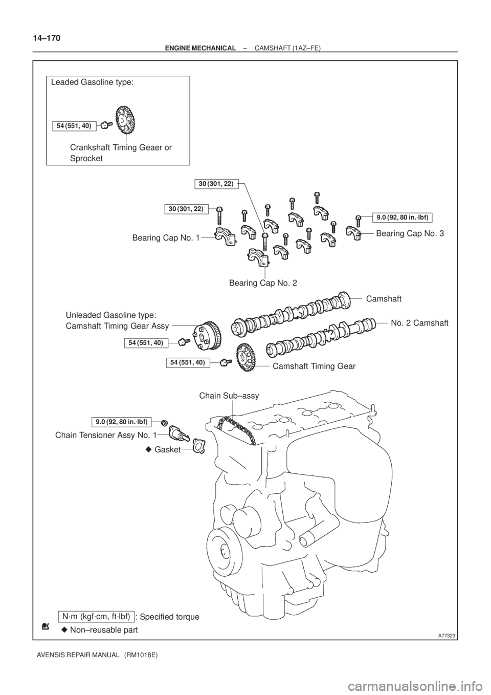
A77323
Leaded Gasoline type:
N´m (kgf´cm, ft´lbf)
: Specified torque
� Non±reusable part
54 (551, 40)
� Gasket
Crankshaft Timing Geaer or
Sprocket
Bearing Cap No. 3
Bearing Cap No. 2
Camshaft
No. 2 Camshaft
Camshaft Timing Gear
Unleaded Gasoline type:
Camshaft Timing Gear Assy
54 (551, 40)
Chain Tensioner Assy No. 1
30 (301, 22)
Bearing Cap No. 1
30 (301, 22)
9.0 (92, 80 in.�lbf)
54 (551, 40)
9.0 (92, 80 in.�lbf)
Chain Sub±assy 14±170
± ENGINE MECHANICALCAMSHAFT (1AZ±FE)
AVENSIS REPAIR MANUAL (RM1018E)
Page 339 of 1690

AVENSIS")
A77285
Unleaded Gasoline
Leaded GasolineTiming
Marks
Timing
Marks Timing
Marks
Timing
Marks
A77286
Push
A77412
HoldLoosen
A77294
15973
481062 14±172
± ENGINE MECHANICALCAMSHAFT (1AZ±FE)
AVENSIS REPAIR MANUAL (RM1018E)
(b) Check that each timing mark of the camshaft timing gears
is aligned with each timing mark located on the No. 1 and
No. 2 bearing caps as shown in the illustration.
If not, turn the crankshaft 1 revolution (360�) and align the
marks as above.
8. REMOVE CHAIN TENSIONER ASSY NO.1
(a) Remove the 2 nuts, then remove the chain tensioner and
a gasket.
NOTICE:
Do not turn the crankshaft.
9. REMOVE NO.2 CAMSHAFT
(a) Hold the No. 2 camshaft with a wrench on the hexagonal
lobe, and loosen the camshaft timing gear set bolt.
NOTICE:
Be careful not to damage the cylinder head and valve lifter
with the wrench.
(b) Using several steps, loosen and remove the 10 camshaft
bearing cap bolts uniformly in the sequence shown in the
illustration.
(c) Remove the 5 camshaft bearing caps.
Page 340 of 1690

14±173
AVENSIS REPAIR MANUAL (RM1018E)
(d) Raising the No. 2 camshaft, remove the set bolt.
(e) Rem")
A52473
A77309
15973
481062
A56228
A77413
Advance
Side Port
± ENGINE MECHANICALCAMSHAFT (1AZ±FE)
14±173
AVENSIS REPAIR MANUAL (RM1018E)
(d) Raising the No. 2 camshaft, remove the set bolt.
(e) Remove the camshaft timing gear from the No. 2 cam-
shaft with the timing chain wrapped.
(f) Remove the camshaft timing gear from the timing chain.
10. REMOVE CAMSHAFT
(a) Using several steps, loosen and remove the 10 camshaft
bearing cap bolts uniformly in the sequence shown in the
illustration.
(b) Remove the 5 camshaft bearings.
(c) Remove the camshaft.
(d) Tie the timing chain as shown in the illustration.
NOTICE:
�Be careful not to drop anything inside the timing
chain cover.
�Do not expose the chain to water, and prevents dust.
11. REMOVE CAMSHAFT TIMING GEAR OR SPROCKET (LEADED GASOLINE)
(a) Clamp the camshaft in a vise and remove the bolt and the camshaft timing gear.
12. REMOVE CAMSHAFT TIMING GEAR ASSY
(UNLEADED GASOLINE)
(a) Fix the camshaft with a vise, and make sure the camshaft
timing gear does not rotate.
(b) Cover all the oil ports with vinyl tape except an advance
side port shown in the illustration.
Page 342 of 1690

14±175
AVENSIS REPAIR MANUA")
A77284
A77415Bearing Cap No. 1Bearing Cap No. 3 5
312 4
A52473
A77416
Bearing Cap No. 2 Bearing Cap No. 3
531 2 4
A77417
TightenHold
± ENGINE MECHANICALCAMSHAFT (1AZ±FE)
14±175
AVENSIS REPAIR MANUAL (RM1018E)
15. INSTALL CAMSHAFT
(a) Turn the crankshaft pulley, and align its groove with timing
mark 0 of the timing chain cover.
(b) Install the timing chain on the camshaft timing gear, with
the painted links aligned with the timing marks on the
camshaft timing gear.
(c) Examine the front marks and numbers and tighten the
bolts in the sequence shown in the illustration.
Torque:
Bearing cap No. 1 30 N�m (301 kgf�cm, 22 ft�lbf)
Bearing cap No. 3 9.0 N�m (92 kgf�cm, 80 in.�lbf)
16. INSTALL NO.2 CAMSHAFT
(a) Put the No. 2 camshaft on the cylinder head with the
painted links of the chain aligned with the timing mark on
the camshaft timing gear.
(b) Raising the No. 2 camshaft, tighten the set bolt temporari-
ly.
(c) Examine the from marks and numbers and tighten the
bolts in the sequence shown in the illustration.
Torque:
Bearing cap No. 2 30 N�m (301 kgf�cm, 22 ft�lbf)
Bearing cap No. 3 9.0 N�m (92 kgf�cm, 80 in.�lbf)
(d) Hold the camshaft with a wrench on the hexagonal lobe,
and tighten the camshaft timing gear set bolt.
Torque: 54 N�m (551 kgf�cm, 40 ft�lbf)
NOTICE:
Be careful not to damage the cylinder head and valve lifter.
Page 347 of 1690
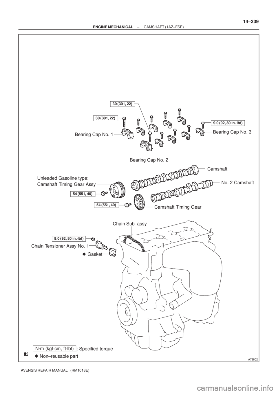
A79802
N´m (kgf´cm, ft´lbf)
: Specified torque
� Non±reusable part� Gasket
Bearing Cap No. 3
Bearing Cap No. 2
Camshaft
No. 2 Camshaft
Camshaft Timing Gear
Unleaded Gasoline type:
Camshaft Timing Gear Assy
54 (551, 40)
Chain Tensioner Assy No. 1
30 (301, 22)
Bearing Cap No. 1
30 (301, 22)
9.0 (92, 80 in.�lbf)
54 (551, 40)
9.0 (92, 80 in.�lbf)
Chain Sub±assy
± ENGINE MECHANICALCAMSHAFT (1AZ±FSE)
14±239
AVENSIS REPAIR MANUAL (RM1018E)
Page 349 of 1690

14±241
AVENSIS REPAIR MANUAL (RM1018E)
(b) Check that each timing")
A77345
Timing
Marks
Timing
Marks
A77286
Push
A77412
HoldLoosen
A77294
15973
481062
A52473
± ENGINE MECHANICALCAMSHAFT (1AZ±FSE)
14±241
AVENSIS REPAIR MANUAL (RM1018E)
(b) Check that each timing mark of the camshaft timing gears
is aligned with each timing mark located on the No. 1 and
No. 2 bearing caps as shown in the illustration.
If not, turn the crankshaft 1 revolution (360�) and align the
marks as above.
13. REMOVE CHAIN TENSIONER ASSY NO.1
(a) Remove the 2 nuts, the chain tensioner and a gasket.
NOTICE:
Do not turn the crankshaft.
14. REMOVE NO.2 CAMSHAFT
(a) Hold the No. 2 camshaft with a wrench on the hexagonal
lobe, and loosen the camshaft timing gear set bolt.
NOTICE:
Be careful not to damage the cylinder head and valve lifter
with the wrench.
(b) Using several steps, loosen and remove the 10 camshaft
bearing cap bolts uniformly in the sequence shown in the
illustration.
(c) Remove the 5 camshaft bearing caps.
(d) Raising the No. 2 camshaft, remove the set bolt.
(e) Remove the camshaft timing gear from the No. 2 cam-
shaft with with the timing chain wrapped.
(f) Remove the camshaft timing gear from the timing chain.