Page 529 of 1690
A77332
23
145
±
ENGINE MECHANICAL PARTIAL ENGINE ASSY(1AZ±FE)
14±129
AVENSIS REPAIR MANUAL (RM1018E)
91.REMOVE KNOCK SENSOR
(a)Remove the nut and the knock sensor.
92.REMOVE ENGINE COOLANT TEMPERATURE SENSOR
(a)Using SST, remove the engine coolant temperature sensor.
SST09817±33190
93.REPLACE PARTIAL ENGINE ASSY
94.INSTALL ENGINE COOLANT TEMPERATURE SENSOR
(a)Install a new gasket to the engine coolant temperature sensor.
(b)Install the engine coolant temperature sensor. Torque: 20 N �m (208 kgf �cm,15 ft �lbf)
SST09817±33190
95.INSTALL KNOCK SENSOR
Torque: 20 N �m (208 kgf �cm,15 ft �lbf)
96.INSTALL ENGINE OIL PRESSURE SWITCH ASSY
(a)Clean the threads of the oil pressure switch, apply adhesive there. Adhesive: Part No. 08833±00080 THREE BOND 1344 or equivalent
(b)Install the oil pressure switch. Torque: 15 N �m (153 kgf �cm,11 ft �lbf)
97.INSTALL WATER BY±PASS PIPE NO.1
(a)Install a new gasket and the water by±pass pipe No. 1 with the bolt a\
nd 2 nuts. Torque: 9.0 N �m (92 kgf �cm,80 in. �lbf)
98.INSTALL FUEL DELIVERY PIPE W/INJECTOR (See page 11±26)
99.INSTALL DRIVE SHAFT BEARING BRACKET Torque: 54 N �m (551 kgf �cm,40 ft �lbf)
100.INSTALL V±RIBBED BELT TENSIONER ASSY
Torque: 60 N �m (607 kgf �cm,44 ft �lbf)
101.INSTALL IGNITION COIL ASSY Torque: 9.0 N �m (92 kgf �cm,80 in. �lbf)
102.INSTALL THERMOSTAT (See page 16±23)
103. INSTALL WATER INLET
Torque: 9.0 N �m (92 kgf �cm, 80 in. �lbf)
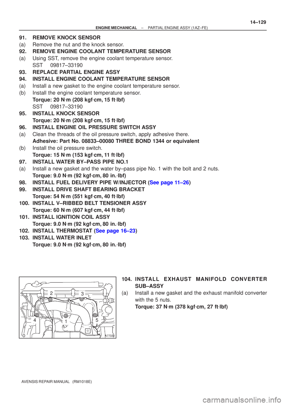
104. I N S TA L L E X HAUST MANIFOLD CONVERTER
SUB±ASSY
(a) Install a new gasket and the exhaust manifold converter
with the 5 nuts.
Torque: 37 N �m (378 kgf �cm, 27 ft �lbf)
Page 539 of 1690
A79421N´m (kgf´cm, ft´lbf)
: Specified torque
88 (897, 65)
19 (195, 14)
64 (653, 47)
37 (377, 27)
Drive Shaft Bearing Bracket
Flywheel Sub±assy
Clutch Cover Assy
Starter Assy
Manual Transaxle
Clutch Disc Assy
64 (653, 47)
± ENGINE MECHANICALPARTIAL ENGINE ASSY (1CD±FTV)
14±281
AVENSIS REPAIR MANUAL (RM1018E)
Page 548 of 1690
A62711
A79180
A61186
SST
14±290
±
ENGINE MECHANICAL PARTIAL ENGINE ASSY(1CD±FTV)
AVENSIS REPAIR MANUAL (RM1018E)
(i)Attach the engine sling and hang the engine with the chain block.
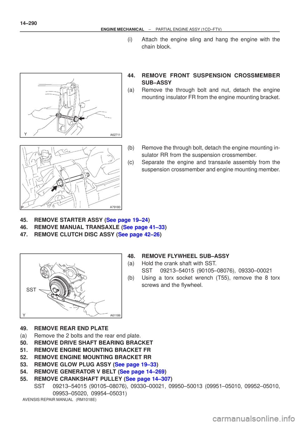
44.REMOVE FRONT SUSPENSION CROSSMEMBER SUB±ASSY
(a)Remove the through bolt and nut, detach the engine mounting insulator FR from the engine mounting bracket.
(b)Remove the through bolt, detach the engine mounting in- sulator RR from the suspension crossmember.
(c)Separate the engine and transaxle assembly from the suspension crossmember and engine mounting member.
45.REMOVE STARTER ASSY (See page 19±24)
46.REMOVE MANUAL TRANSAXLE (See page 41±33)
47.REMOVE CLUTCH DISC ASSY (See page 42±26) 48. REMOVE FLYWHEEL SUB±ASSY
(a) Hold the crank shaft with SST.SST 09213±54015 (90105±08076), 09330±00021
(b) Using a torx socket wrench (T55), remove the 8 torx
screws and the flywheel.
49. REMOVE REAR END PLATE
(a) Remove the 2 bolts and the rear end plate.
50. REMOVE DRIVE SHAFT BEARING BRACKET
51. REMOVE ENGINE MOUNTING BRACKET FR
52. REMOVE ENGINE MOUNTING BRACKET RR
53.REMOVE GLOW PLUG ASSY (See page 19±33)
54.REMOVE GENERATOR V BELT (See page 14±269)
55.REMOVE CRANKSHAFT PULLEY (See page 14±307) SST 09213±54015 (90105±08076), 09330±00021, 09950±50013 (0995\
1±05010, 09952±05010, 09953±05020, 09954±05031)
Page 558 of 1690
A61186
SST
A57108
Adhesive
14±300
±
ENGINE MECHANICAL PARTIAL ENGINE ASSY (1CD±FTV)
AVENSIS REPAIR MANUAL (RM1018E)
147. INSTALL OIL FILTER BRACKET SUB±ASSY
(a) Install a new gasket and oil filter bracket with the bolt and 2 nuts. Torque: 34 N �m (347 kgf �cm, 25 ft �lbf)
148. INSTALL V±RIBBED BELT TENSIONER ASSY Torque: 31 N �m (316 kgf �cm, 23 ft �lbf)
149. INSTALL GENERATOR BRACKET NO.1 Torque: 37 N �m (377 kgf �cm, 27 ft �lbf)
150.INSTALL GENERATOR ASSY (See page 19±29)
151.SET NO. 1 CYLINDER TO TDC/COMPRESSION (See page 14±307) SST 09960±10010 (09962±01000, 09963±01000)
152.INSTALL TIMING BELT (See page 14±307)
153.CHECK VALVE TIMING (See page 14±307)
154.INSTALL TRANSVERSE ENGINE ENGINE MOUNTING BRACKET (See page 14±307)
155.INSTALL TIMING BELT GUIDE (See page 14±307)
156.INSTALL TIMING BELT NO.1 COVER (See page 14±307)
157.INSTALL TIMING BELT NO.2 COVER (See page 14±307)
158. INSTALL IDLER PULLEY SUB±ASSY Torque: 40 N �m (408 kgf �cm, 30 ft �lbf)
159.INSTALL CRANKSHAFT PULLEY (See page 14±307) SST 09213±54015 (90105±08076), 09330±00021
160.INSTALL GLOW PLUG ASSY (See page 19±33)
161. INSTALL ENGINE MOUNTING BRACKET RR Torque: 64 N �m (653 kgf �cm, 47 ft �lbf)
162. INSTALL ENGINE MOUNTING BRACKET FR Torque: 64 N �m (653 kgf �cm, 47 ft �lbf)
163. INSTALL DRIVE SHAFT BEARING BRACKET Torque: 64 N �m (653 kgf �cm, 47 ft �lbf)
164. INSTALL REAR END PLATE Torque: 8.4 N �m (86 kgf �cm, 74 in. �lbf)
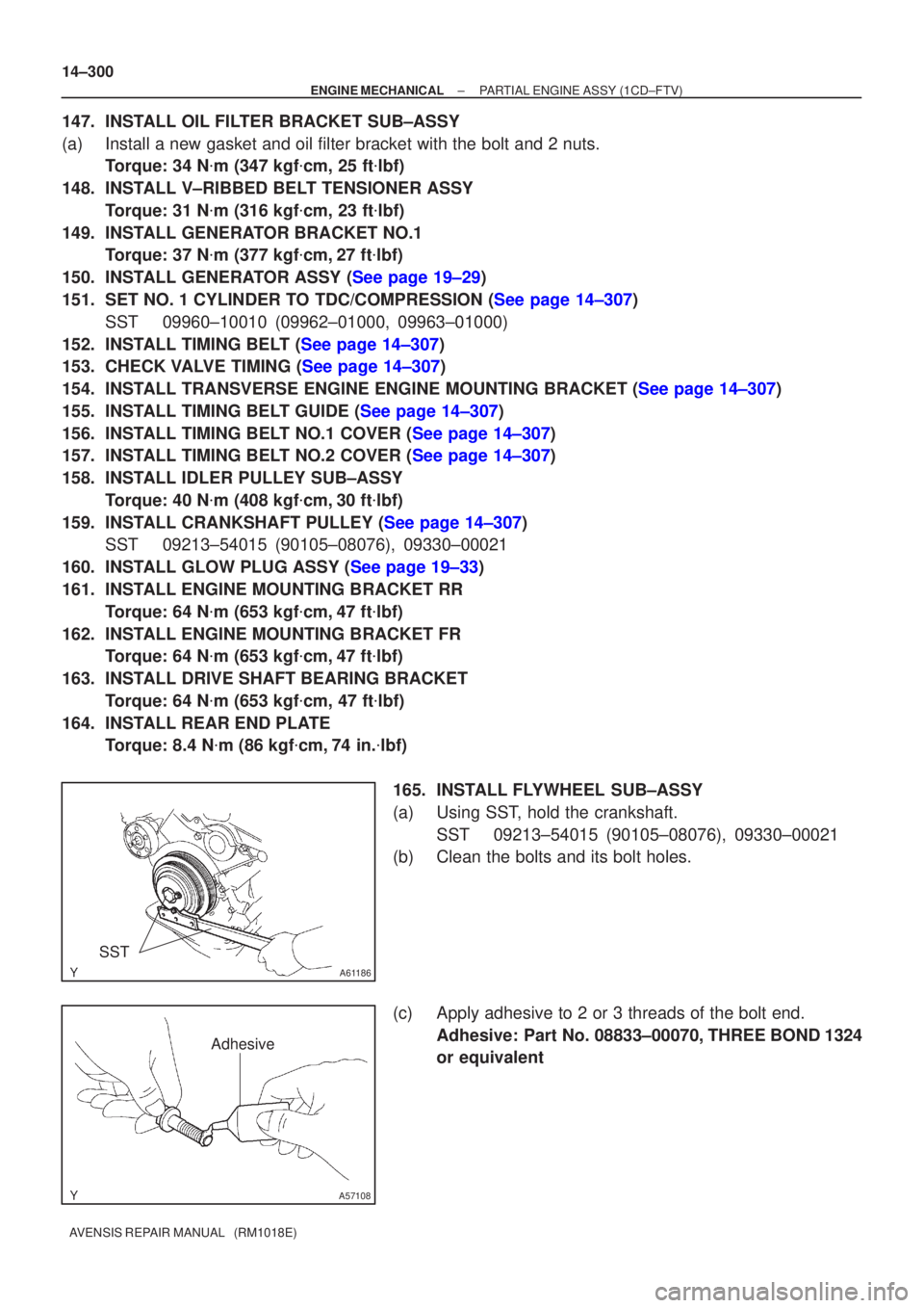
165. INSTALL FLYWHEEL SUB±ASSY
(a) Using SST, hold the crankshaft. SST 09213±54015 (90105±08076), 09330±00021
(b) Clean the bolts and its bolt holes.
(c) Apply adhesive to 2 or 3 threads of the bolt end.
Adhesive: Part No. 08833±00070, THREE BOND 1324
or equivalent
Page 613 of 1690
A62188
24 5 3 1
A32124
A6218924 31
A32125
A32556
14±10
± ENGINE MECHANICALVALVE CLEARANCE (1ZZ±FE/3ZZ±FE)
AVENSIS REPAIR MANUAL (RM1018E)
(e) Using several steps, loosen the camshaft bearing cap
bolts on the No. 2 camshaft in the sequence shown in the
illustration and remove the bearing caps.
(f) Remove the camshaft timing gear as shown in the illustra-
tion.
(g) Using several steps, loosen the camshaft bearing cap
bolts on the camshaft in the sequence shown in the il-
lustration and remove the bearing caps.
(h) Remove the camshaft while holding the timing chain.
(i) Tie the timing chain with a string as shown in the illustra-
tion.
NOTICE:
Be careful not to drop anything inside the timing chain cov-
er.
Page 617 of 1690
A62195
Painted Link
Timing Mark
A62196
4123
A62197
Painted Link
Timing Mark
A32124
A621983124 5 67 14±14
± ENGINE MECHANICALVALVE CLEARANCE (1ZZ±FE/3ZZ±FE)
AVENSIS REPAIR MANUAL (RM1018E)
(m) Install the timing chain on the camshaft timing gear with
the painted links aligned with the timing marks on the
camshaft timing sprocket as shown in the illustration.
(n) Examine the front marks and numbers and tighten the
bolts in the sequence shown in the illustration.
Torque: 13 N�m (133 kgf�cm, 10 ft�lbf)
(o) Put the camshaft No.2 on the cylinder head with the
painted links of the chain aligned with the timing mark on
the camshaft timing sprocket.
(p) Tighten the camshaft timing gear set bolt temporarily.
(q) Examine the front marks and numbers and tighten the
bolts in the sequence shown in the illustration.
Torque: 13 N�m (133 kgf�cm, 10 ft�lbf)
(r) Install the bearing cap No. 1.
Torque: 23 N�m (235 kgf�cm, 17 ft�lbf)
Page 712 of 1690
2600K±06
±
FRONT SUSPENSION FRONT SUSPENSION SYSTEM
26±1
AVENSIS REPAIR MANUAL (RM1018E)
FRONT SUSPENSION SYSTEM
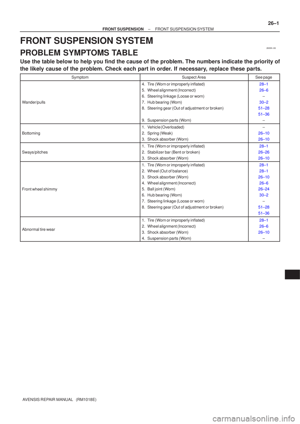
PROBLEM SYMPTOMS TABLE
Use the table below to help you find the cause of the problem. The numbers \
indicate the priority of
the likely cause of the problem. Check each part in order. If necessary, replace these parts.
SymptomSuspect AreaSee page
Wander/pulls
4. Tire (Worn or improperly inflated)
5. Wheel alignment (Incorrect)
6. Steering linkage (Loose or worn)
7. Hub bearing (Worn)
8. Steering gear (Out of adjustment or broken)
9. Suspension parts (Worn)28±1
26±6
±
30±2
51±28
51±36
±
Bottoming
1. Vehicle (Overloaded)
2. Spring (Weak)
3. Shock absorber (Worn)±
26±10
26±10
Sways/pitches
1. Tire (Worn or improperly inflated)
2. Stabilizer bar (Bent or broken)
3. Shock absorber (Worn)28±1
26±26
26±10
Front wheel shimmy
1. Tire (Worn or improperly inflated)
2. Wheel (Out of balance)
3. Shock absorber (Worn)
4. Wheel alignment (Incorrect)
5. Ball joint (Worn)
6. Hub bearing (Worn)
7. Steering linkage (Loose or worn)
8. Steering gear (Out of adjustment or broken)28±1
28±1
26±10 26±6
26±24
30±2 ±
51±28
51±36
Abnormal tire wear
1. Tire (Worn or improperly inflated)
2. Wheel alignment (Incorrect)
3. Shock absorber (Worn)
4. Suspension parts (Worn)28±1
26±6
26±10 ±
Page 821 of 1690
A79187
O±ringBack±up ring
B08249
A80111
180�
90� 11±62
± FUELINJECTOR ASSY (1CD±FTV)
AVENSIS REPAIR MANUAL (RM1018E)
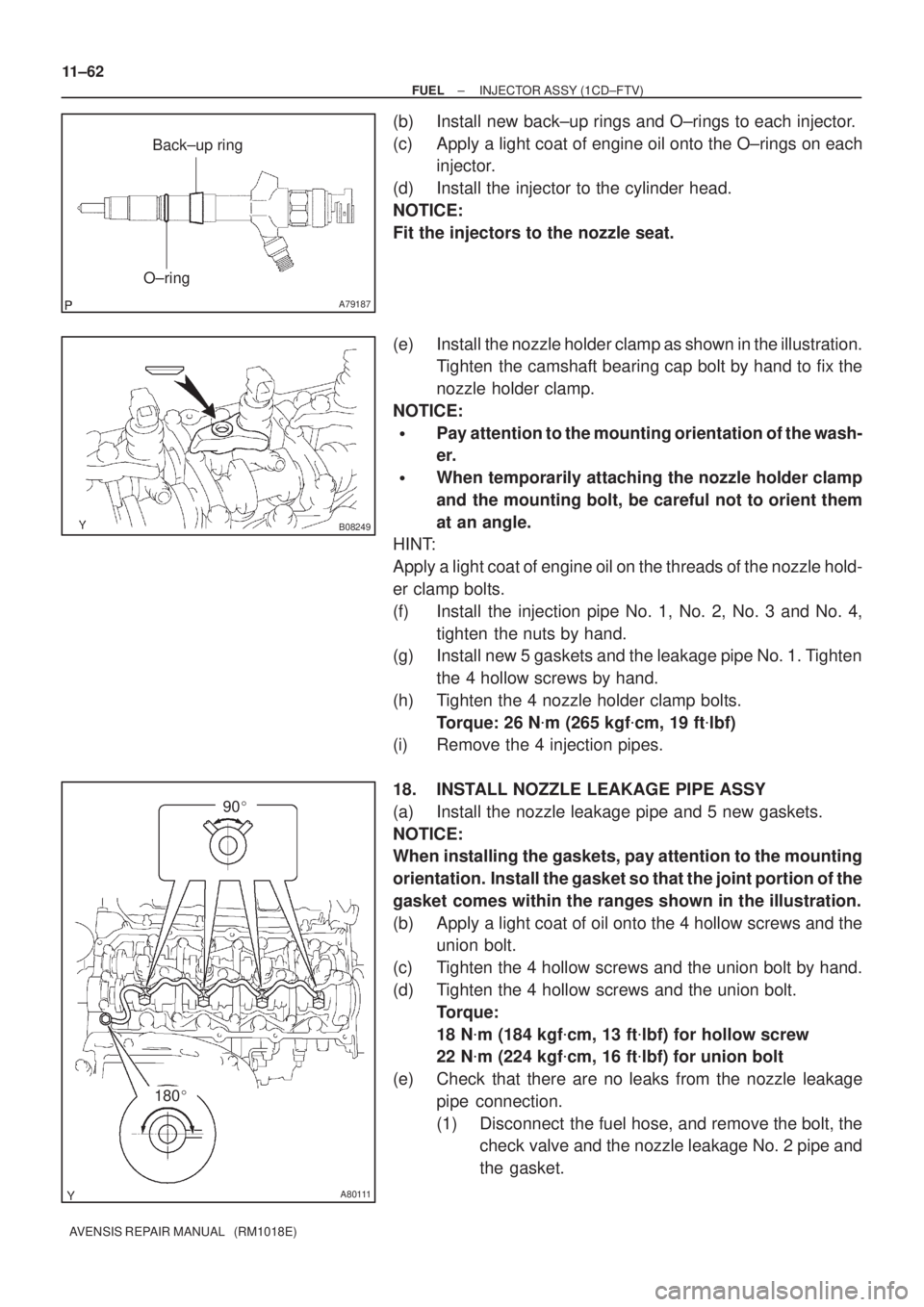
(b) Install new back±up rings and O±rings to each injector.
(c) Apply a light coat of engine oil onto the O±rings on each
injector.
(d) Install the injector to the cylinder head.
NOTICE:
Fit the injectors to the nozzle seat.
(e) Install the nozzle holder clamp as shown in the illustration.
Tighten the camshaft bearing cap bolt by hand to fix the
nozzle holder clamp.
NOTICE:
�Pay attention to the mounting orientation of the wash-
er.
�When temporarily attaching the nozzle holder clamp
and the mounting bolt, be careful not to orient them
at an angle.
HINT:
Apply a light coat of engine oil on the threads of the nozzle hold-
er clamp bolts.
(f) Install the injection pipe No. 1, No. 2, No. 3 and No. 4,
tighten the nuts by hand.
(g) Install new 5 gaskets and the leakage pipe No. 1. Tighten
the 4 hollow screws by hand.
(h) Tighten the 4 nozzle holder clamp bolts.
Torque: 26 N�m (265 kgf�cm, 19 ft�lbf)
(i) Remove the 4 injection pipes.
18. INSTALL NOZZLE LEAKAGE PIPE ASSY
(a) Install the nozzle leakage pipe and 5 new gaskets.
NOTICE:
When installing the gaskets, pay attention to the mounting
orientation. Install the gasket so that the joint portion of the
gasket comes within the ranges shown in the illustration.
(b) Apply a light coat of oil onto the 4 hollow screws and the
union bolt.
(c) Tighten the 4 hollow screws and the union bolt by hand.
(d) Tighten the 4 hollow screws and the union bolt.
Torque:
18 N�m (184 kgf�cm, 13 ft�lbf) for hollow screw
22 N�m (224 kgf�cm, 16 ft�lbf) for union bolt
(e) Check that there are no leaks from the nozzle leakage
pipe connection.
(1) Disconnect the fuel hose, and remove the bolt, the
check valve and the nozzle leakage No. 2 pipe and
the gasket.