Page 965 of 1690
1302Y±03
A77119
A77120
A77121
± INTAKETURBO CHARGER SYSTEM (1CD±FTV)
13±3
AVENSIS REPAIR MANUAL (RM1018E)
TURBO CHARGER SYSTEM (1CD±FTV)
PRECAUTION
1. MAINTENANCE PRECAUTION
(a) Do not stop the engine immediately after pulling a trailer,
or after driving at a high speed, or uphill drive. Let the en-
gine Idle for 20 to 120 seconds before turn the ignition
switch OFF (According as the driving condition, the idling
time varies).
(b) Avoid quick acceleration or quickly accelerating the en-
gine RPM immediately after the starting a cold engine.
(c) If the turbocharger is found to be defective, it must be re-
placed. Also, inspect a source of the trouble including
conditions of the turbocharger that having been used. Re-
pair or replace the followings as necessary:
(1) Engine oil (Level and quality)
(2) Oil lines leading to the turbocharger
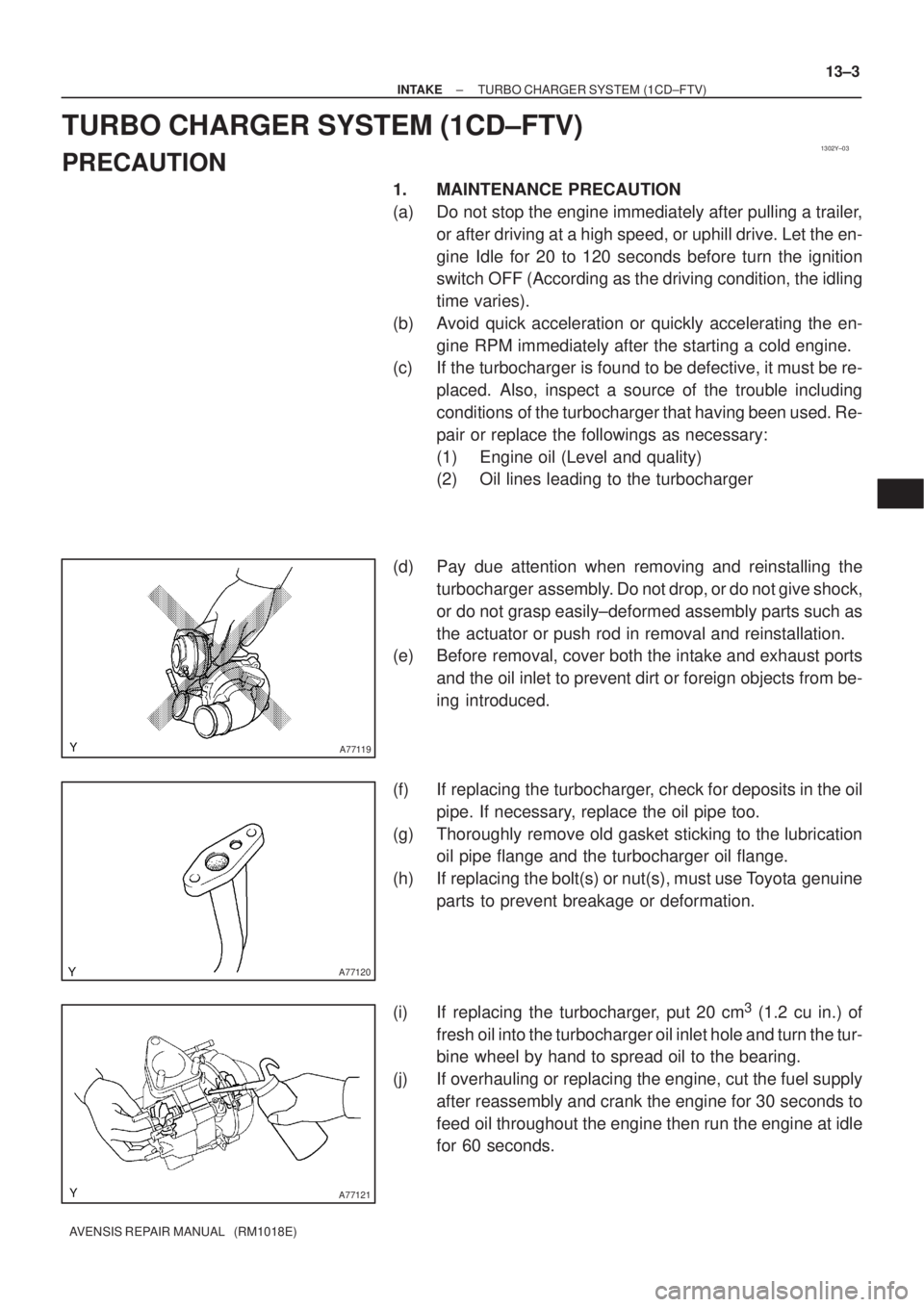
(d) Pay due attention when removing and reinstalling the
turbocharger assembly. Do not drop, or do not give shock,
or do not grasp easily±deformed assembly parts such as
the actuator or push rod in removal and reinstallation.
(e) Before removal, cover both the intake and exhaust ports
and the oil inlet to prevent dirt or foreign objects from be-
ing introduced.
(f) If replacing the turbocharger, check for deposits in the oil
pipe. If necessary, replace the oil pipe too.
(g) Thoroughly remove old gasket sticking to the lubrication
oil pipe flange and the turbocharger oil flange.
(h) If replacing the bolt(s) or nut(s), must use Toyota genuine
parts to prevent breakage or deformation.
(i) If replacing the turbocharger, put 20 cm
3 (1.2 cu in.) of
fresh oil into the turbocharger oil inlet hole and turn the tur-
bine wheel by hand to spread oil to the bearing.
(j) If overhauling or replacing the engine, cut the fuel supply
after reassembly and crank the engine for 30 seconds to
feed oil throughout the engine then run the engine at idle
for 60 seconds.
Page 1076 of 1690
B08009
A56697
A56698
A56699
17±24
± LUBRICATIONOIL PUMP ASSY (1CD±FTV)
AVENSIS REPAIR MANUAL (RM1018E)
31. REMOVE OIL PAN INSULATOR
(a) Remove the bolt and the oil pan insulator.
32. REMOVE OIL PAN SUB±ASSY
(a) Remove the 19 bolts and 3 nuts.
(b) Using a screwdriver, remove the oil pan by prying be-
tween the cylinder block and the No. 1 oil pan.
NOTICE:
Be careful not to damage the cylinder block and No. 1 oil
pan.
33. REMOVE CRANKSHAFT POSITION SENSOR
34. REMOVE OIL PUMP ASSY
(a) Remove the 9 bolts.
(b) Remove the oil pump by prying between the oil pump and
the main bearing cap with a screwdriver.
(c) Remove the gasket.
Page 1112 of 1690
4100Y±05
±
MANUAL TRANSMISSION/TRANSAXLE MANUAL TRANSAXLE SYSTEM (MTM)
41±1
AVENSIS REPAIR MANUAL (RM1018E)
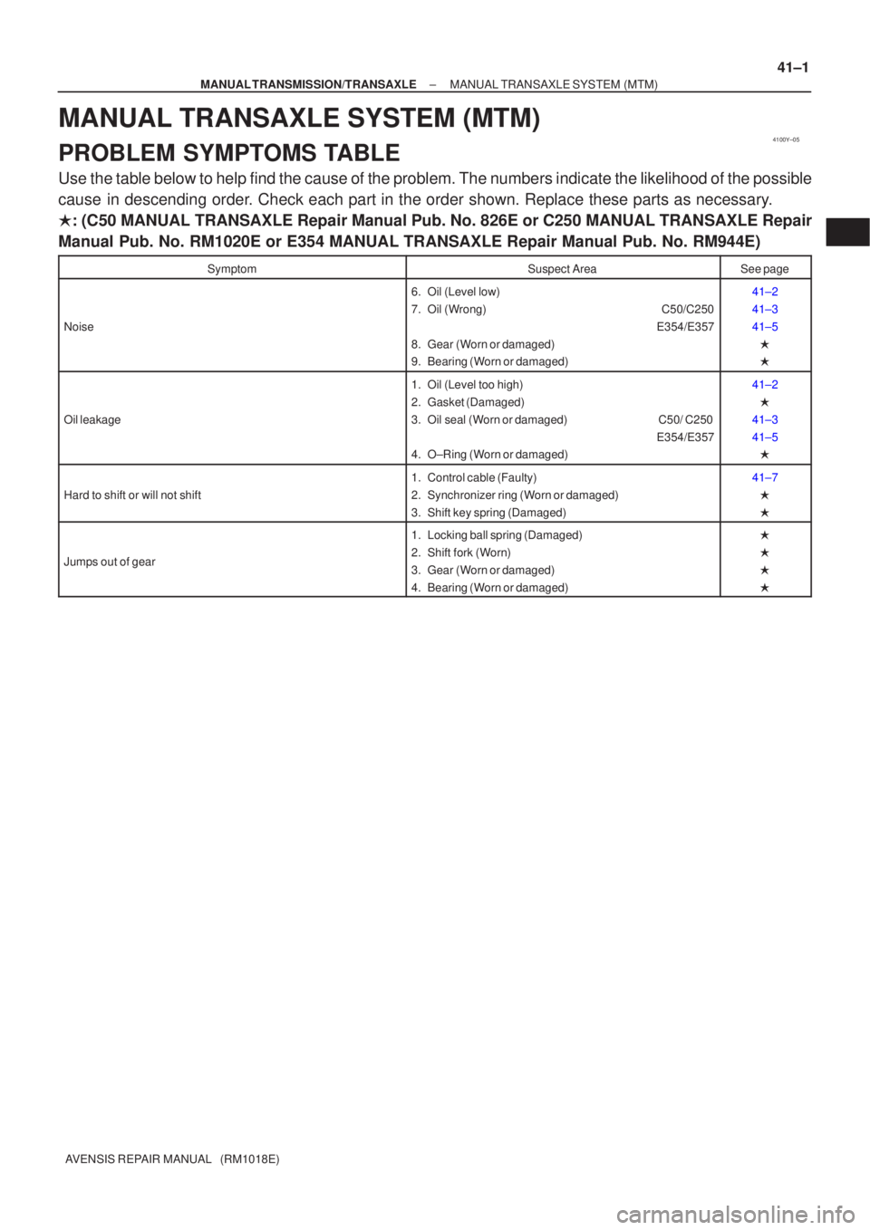
MANUAL TRANSAXLE SYSTEM (MTM)
PROBLEM SYMPTOMS TABLE
Use the table below to help find the cause of the problem. The numbers indi\
cate the likelihood of the possible
cause in descending order. Check each part in the order shown. Replace these parts as necessary.
�: (C50 MANUAL TRANSAXLE Repair Manual Pub. No. 826E or C250 MANUAL TRANS\
AXLE Repair
Manual Pub. No. RM1020E or E354 MANUAL TRANSAXLE Repair Manual Pub. No. RM944E\
)
SymptomSuspect AreaSee page
Noise
6. Oil (Level low)
7. Oil (Wrong) C50/C250
E354/E357
8. Gear (Worn or damaged)
9. Bearing (Worn or damaged)41±2
41±3
41±5 �
�
Oil leakage
1. Oil (Level too high)
2. Gasket (Damaged)
3. Oil seal (Worn or damaged) C50/ C250 E354/E357
4. O±Ring (Worn or damaged)41±2
�
41±3
41±5 �
Hard to shift or will not shift
1. Control cable (Faulty)
2. Synchronizer ring (Worn or damaged)
3. Shift key spring (Damaged)41±7
�
�
Jumps out of gear
1. Locking ball spring (Damaged)
2. Shift fork (Worn)
3. Gear (Worn or damaged)
4. Bearing (Worn or damaged)�
�
�
�
Page 1136 of 1690
5100G±06
51±2
±
POWER STEERING POWER STEERING SYSTEM
AVENSIS REPAIR MANUAL (RM1018E)
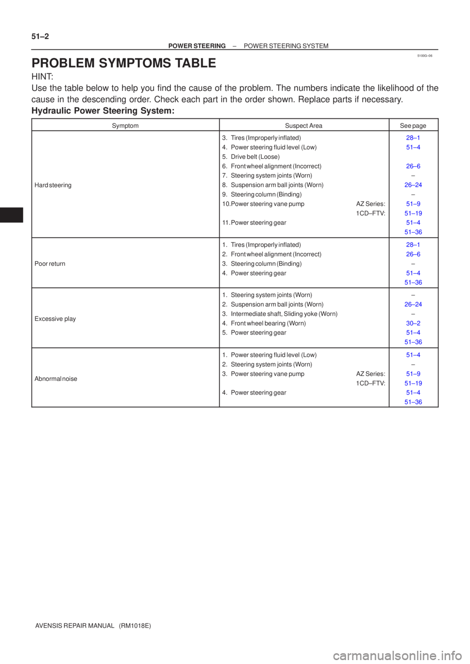
PROBLEM SYMPTOMS TABLE
HINT:
Use the table below to help you find the cause of the problem. The numbers \
indicate the likelihood of the
cause in the descending order. Check each part in the order shown. Replace parts if necessary.
Hydraulic Power Steering System:
SymptomSuspect AreaSee page
Hard steering
3. Tires (Improperly inflated)
4. Power steering fluid level (Low)
5. Drive belt (Loose)
6. Front wheel alignment (Incorrect)
7. Steering system joints (Worn)
8. Suspension arm ball joints (Worn)
9. Steering column (Binding)
10.Power steering vane pump AZ Series: 1CD±FTV:
11. Power steering gear28±1
51±4
26±6 ±
26±24 ±
51±9
51±19 51±4
51±36
Poor return
1. Tires (Improperly inflated)
2. Front wheel alignment (Incorrect)
3. Steering column (Binding)
4. Power steering gear28±1
26±6 ±
51±4
51±36
Excessive play
1. Steering system joints (Worn)
2. Suspension arm ball joints (Worn)
3. Intermediate shaft, Sliding yoke (Worn)
4. Front wheel bearing (Worn)
5. Power steering gear±
26±24 ±
30±2
51±4
51±36
Abnormal noise
1. Power steering fluid level (Low)
2. Steering system joints (Worn)
3. Power steering vane pump AZ Series: 1CD±FTV:
4. Power steering gear51±4
±
51±9
51±19 51±4
51±36
Page 1137 of 1690
±
POWER STEERING POWER STEERING SYSTEM
51±3
AVENSIS REPAIR MANUAL (RM1018E)
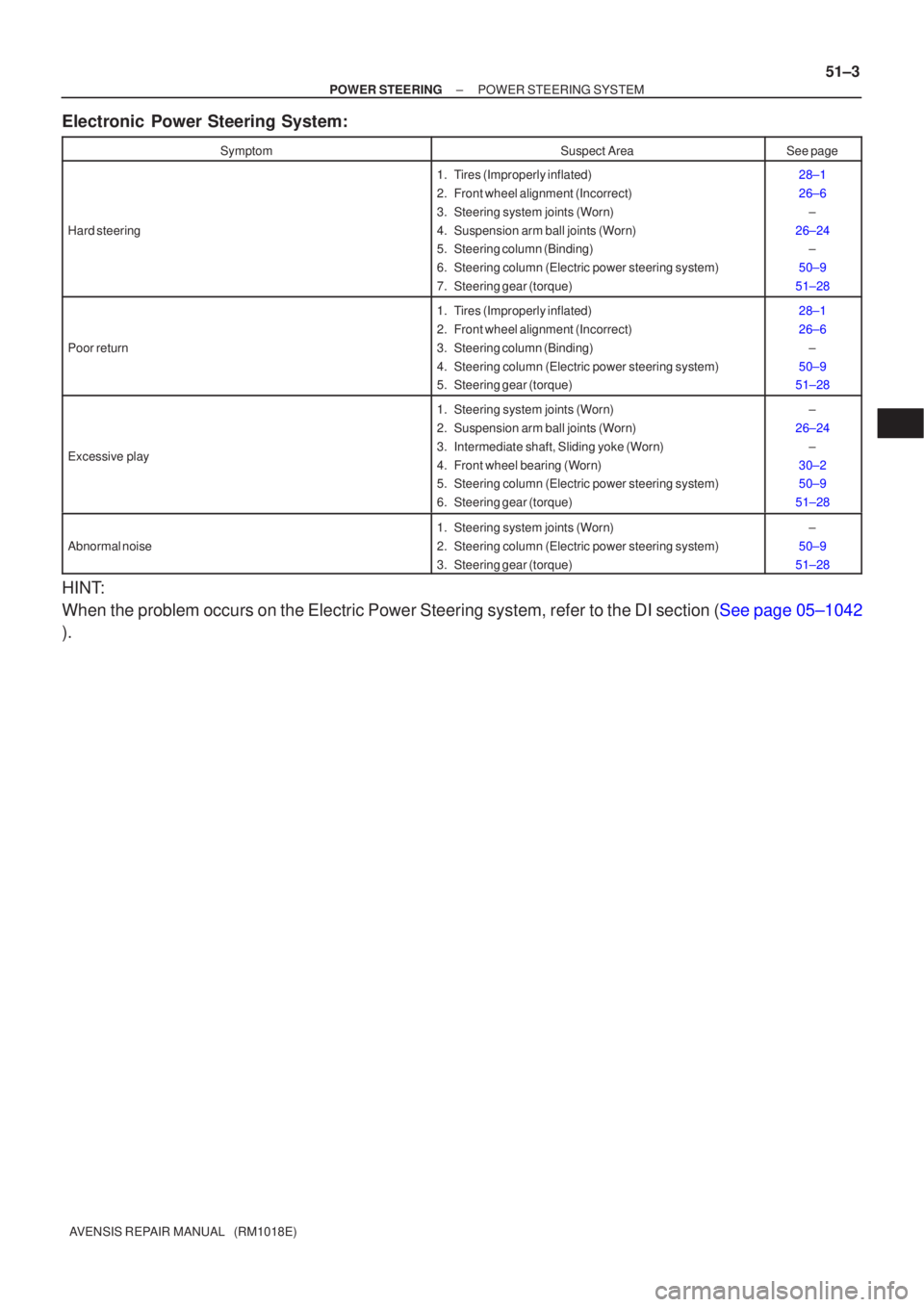
Electronic Power Steering System:
SymptomSuspect AreaSee page
Hard steering
1. Tires (Improperly inflated)
2. Front wheel alignment (Incorrect)
3. Steering system joints (Worn)
4. Suspension arm ball joints (Worn)
5. Steering column (Binding)
6. Steering column (Electric power steering system)
7. Steering gear (torque)28±1
26±6
±
26±24 ±
50±9
51±28
Poor return
1. Tires (Improperly inflated)
2. Front wheel alignment (Incorrect)
3. Steering column (Binding)
4. Steering column (Electric power steering system)
5. Steering gear (torque)28±1
26±6 ±
50±9
51±28
Excessive play
1. Steering system joints (Worn)
2. Suspension arm ball joints (Worn)
3. Intermediate shaft, Sliding yoke (Worn)
4. Front wheel bearing (Worn)
5. Steering column (Electric power steering system)
6. Steering gear (torque)±
26±24 ±
30±2
50±9
51±28
Abnormal noise
1. Steering system joints (Worn)
2. Steering column (Electric power steering system)
3. Steering gear (torque)±
50±9
51±28
HINT:
When the problem occurs on the Electric Power Steering system, refer to \
the DI section (See page 05±1042
).
Page 1181 of 1690
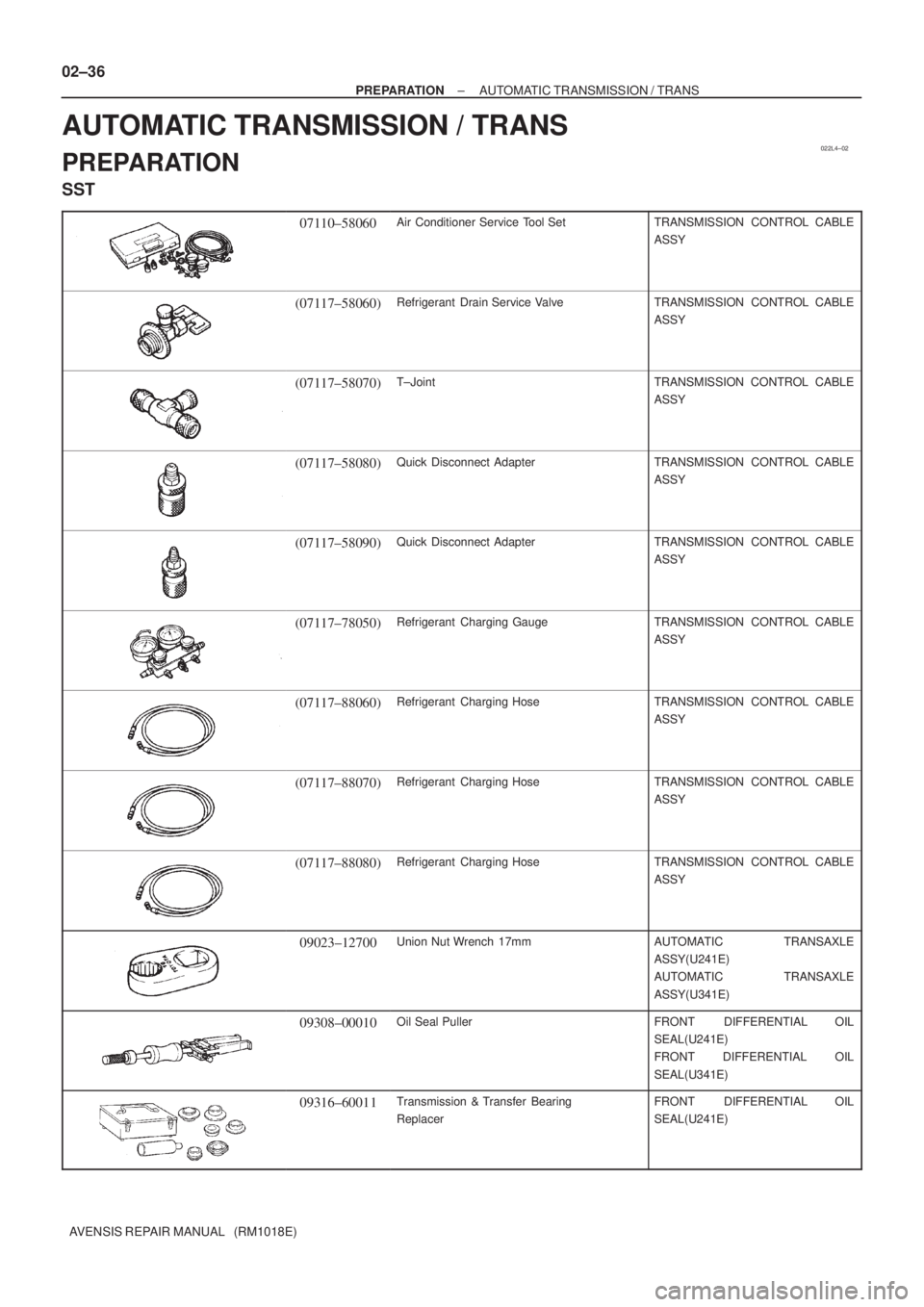
022L4±02
02±36
± PREPARATIONAUTOMATIC TRANSMISSION / TRANS
AVENSIS REPAIR MANUAL (RM1018E)
AUTOMATIC TRANSMISSION / TRANS
PREPARATION
SST
07110±58060Air Conditioner Service Tool SetTRANSMISSION CONTROL CABLE
ASSY
(07117±58060)Refrigerant Drain Service ValveTRANSMISSION CONTROL CABLE
ASSY
(07117±58070)T±JointTRANSMISSION CONTROL CABLE
ASSY
(07117±58080)Quick Disconnect AdapterTRANSMISSION CONTROL CABLE
ASSY
(07117±58090)Quick Disconnect AdapterTRANSMISSION CONTROL CABLE
ASSY
(07117±78050)Refrigerant Charging GaugeTRANSMISSION CONTROL CABLE
ASSY
(07117±88060)Refrigerant Charging HoseTRANSMISSION CONTROL CABLE
ASSY
(07117±88070)Refrigerant Charging HoseTRANSMISSION CONTROL CABLE
ASSY
(07117±88080)Refrigerant Charging HoseTRANSMISSION CONTROL CABLE
ASSY
09023±12700Union Nut Wrench 17mmAUTOMATIC TRANSAXLE
ASSY(U241E)
AUTOMATIC TRANSAXLE
ASSY(U341E)
09308±00010Oil Seal PullerFRONT DIFFERENTIAL OIL
SEAL(U241E)
FRONT DIFFERENTIAL OIL
SEAL(U341E)
09316±60011Transmission & Transfer Bearing
ReplacerFRONT DIFFERENTIAL OIL
SEAL(U241E)
Page 1185 of 1690
022KS±01
± PREPARATIONBRAKE
02±33
AVENSIS REPAIR MANUAL (RM1018E)
BRAKE
PREPARATION
SST
09023±00100Union Nut Wrench 10 mmBRAKE FLUID
BRAKE MASTER CYLINDER
SUB±ASSY
FRONT BRAKE
REAR BRAKE
BRAKE BOOSTER ASSY(LHD)
BRAKE BOOSTER ASSY(RHD)
BRAKE ACTUATOR ASSY(W/ VSC)
BRAKE ACTUATOR ASSY(W/O VSC)
09023±38400Union Nut Wrench 14mmBRAKE FLUID
BRAKE MASTER CYLINDER
SUB±ASSY
FRONT BRAKE
REAR BRAKE
BRAKE BOOSTER ASSY(LHD)
BRAKE BOOSTER ASSY(RHD)
BRAKE ACTUATOR ASSY(W/ VSC)
09214±76011Crankshaft Pulley ReplacerSKID CONTROL SENSOR
09520±00031Rear Axle Shaft PullerSKID CONTROL SENSOR
(09520±00040)ShockerSKID CONTROL SENSOR
09521±00020Drive Shaft Boot Clamping ToolSKID CONTROL SENSOR
09550±60010Differential Side Bearing
ReplacerFRONT BRAKE
(09710±06051)ReplacerREAR BRAKE
09950±00020Bearing RemoverSKID CONTROL SENSOR
Recomended Tools
09042±00010Torx Socket T30STEERING SENSOR
Page 1187 of 1690
022KZ±01
± PREPARATIONCLUTCH
02±43
AVENSIS REPAIR MANUAL (RM1018E)
CLUTCH
PREPARATION
SST
09023±00100Union Nut Wrench 10 mmCLUTCH ACCUMULATOR
ASSY(1CD±FTV)
CLUTCH RELEASE CYLINDER
ASSY(MTM)
CLUTCH MASTER CYLINDER
ASSY(MTM)
09301±00220Clutch Guide ToolCLUTCH UNIT(MTM)
09333±00013Universal Joint Bearing Remover
& ReplacerCLUTCH UNIT(MTM)
Recomended Tools
09040±00011Hexagon Wrench SetCLUTCH PEDAL SUB±ASSY(MTM)
Equipment
Torque wrench
Vernier calipers
Dial indicator with magnetic base
Vernier calipers
Lubricant
ItemCapacityClassification
Brake fluid±SAE J1704 or FMVSS No.116 DOT 4