Page 73 of 1690
G23179
F45705
F41543
Matchmarks
F45706
±
BRAKE FRONT BRAKE
32±43
AVENSIS REPAIR MANUAL (RM1018E)
11.REMOVE FRONT DISC BRAKE BLEEDER PLUG
(a)Remove the bleeder plug cap and front disc brake bleeder plug from the disc b\
rake cylinder assy LH.
12.INSPECT BRAKE CYLINDER AND PISTON
(a)Check the cylinder bore and piston for rust or scoring.
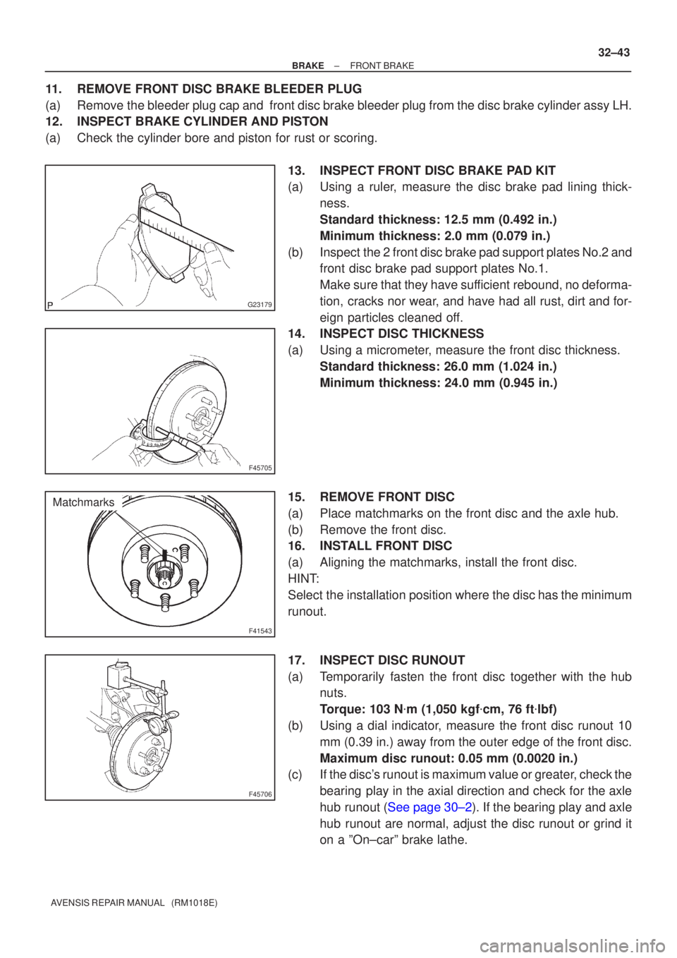
13.INSPECT FRONT DISC BRAKE PAD KIT
(a)Using a ruler, measure the disc brake pad lining thick-ness.
Standard thickness: 12.5 mm (0.492 in.)
Minimum thickness: 2.0 mm (0.079 in.)
(b)Inspect the 2 front disc brake pad support plates No.2 and front disc brake pad support plates No.1.
Make sure that they have sufficient rebound, no deforma-
tion, cracks nor wear, and have had all rust, dirt and for-
eign particles cleaned off.
14.INSPECT DISC THICKNESS
(a)Using a micrometer, measure the front disc thickness.
Standard thickness: 26.0 mm (1.024 in.)
Minimum thickness: 24.0 mm (0.945 in.)
15.REMOVE FRONT DISC
(a)Place matchmarks on the front disc and the axle hub.
(b)Remove the front disc.
16.INSTALL FRONT DISC
(a)Aligning the matchmarks, install the front disc.
HINT:
Select the installation position where the disc has the minimum
runout.
17.INSPECT DISC RUNOUT
(a)Temporarily fasten the front disc together with the hub nuts.
Torque: 103 N �m (1,050 kgf �cm, 76 ft �lbf)
(b)Using a dial indicator, measure the front disc runout 10 mm (0.39 in.) away from the outer edge of the front disc.
Maximum disc runout: 0.05 mm (0.0020 in.)
(c)If the disc's runout is maximum value or greater, check the
bearing play in the axial direction and check for the axle
hub runout (See page 30±2). If the bearing play and axle
hub runout are normal, adjust the disc runout or grind it
on a ºOn±carº brake lathe.
Page 80 of 1690
F45708
F45750Lithium soap base glycol grease
Cylinder Boot
Piston
G23231Cylinder Boot
Piston
F45704
32±50
±
BRAKE REAR BRAKE
AVENSIS REPAIR MANUAL (RM1018E)
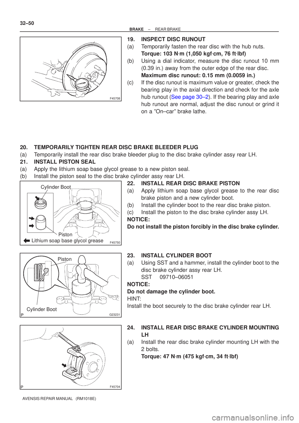
19.INSPECT DISC RUNOUT
(a)Temporarily fasten the rear disc with the hub nuts. Torque: 103 N �m (1,050 kgf �cm, 76 ft �lbf)
(b)Using a dial indicator, measure the disc runout 10 mm (0.39 in.) away from the outer edge of the rear disc.
Maximum disc runout: 0.15 mm (0.0059 in.)
(c)If the disc runout is maximum value or greater, check the
bearing play in the axial direction and check for the axle
hub runout (See page 30±2). If the bearing play and axle
hub runout are normal, adjust the disc runout or grind it
on a ºOn±carº brake lathe.
20. TEMPORARILY TIGHTEN REAR DISC BRAKE BLEEDER PLUG
(a) Temporarily install the rear disc brake bleeder plug to the disc brake cy\
linder assy rear LH.
21. INSTALL PISTON SEAL
(a) Apply the lithium soap base glycol grease to a new piston seal.
(b) Install the piston seal to the disc brake cylinder assy rear LH. 22. INSTALL REAR DISC BRAKE PISTON
(a) Apply lithium soap base glycol grease to the rear discbrake piston and a new cylinder boot.
(b) Install the cylinder boot to the rear disc brake piston.
(c) Install the piston to the disc brake cylinder assy LH.
NOTICE:
Do not install the piston forcibly in the disc brake cylinder.
23. INSTALL CYLINDER BOOT
(a) Using SST and a hammer, install the cylinder boot to the disc brake cylinder assy rear LH.
SST 09710±06051
NOTICE:
Do not damage the cylinder boot.
HINT:
Install the boot securely to the disc brake cylinder rear LH.
24. INSTALL REAR DISC BRAKE CYLINDER MOUNTING LH
(a) Install the rear disc brake cylinder mounting LH with the
2 bolts.
Torque: 47 N �m (475 kgf �cm, 34 ft �lbf)
Page 83 of 1690
320VV±01
G23167
F08657
BoltSST
SST
Bolt
±
BRAKE SKID CONTROL SENSOR
32±61
AVENSIS REPAIR MANUAL (RM1018E)
SKID CONTROL SENSOR
REPLACEMENT
HINT:
Replace the RH side by using the same procedures as those for the LH side.
1. REMOVE REAR WHEEL
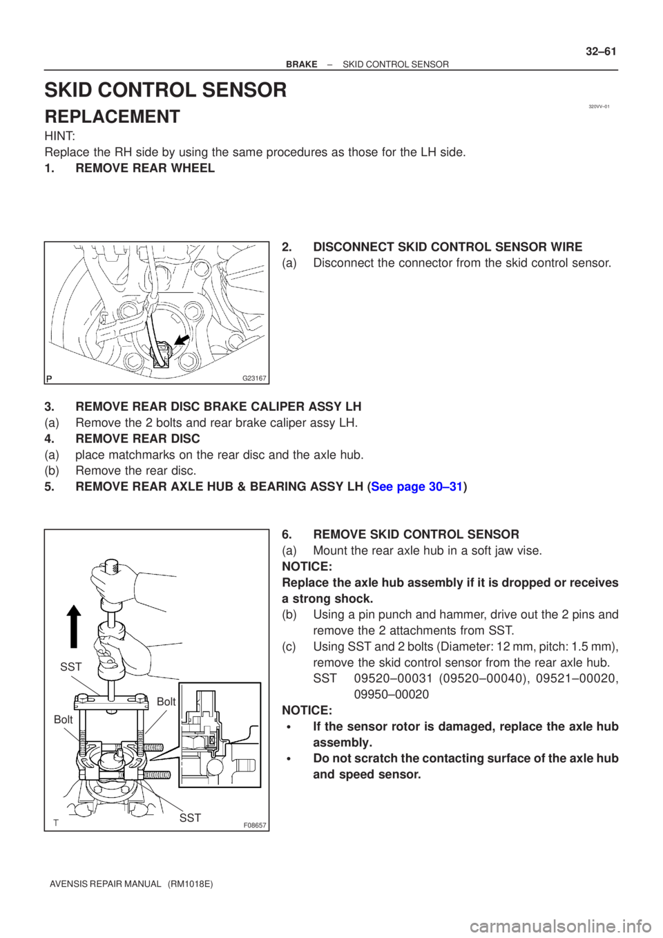
2. DISCONNECT SKID CONTROL SENSOR WIRE
(a) Disconnect the connector from the skid control sensor.
3. REMOVE REAR DISC BRAKE CALIPER ASSY LH
(a) Remove the 2 bolts and rear brake caliper assy LH.
4. REMOVE REAR DISC
(a) place matchmarks on the rear disc and the axle hub.
(b) Remove the rear disc.
5.REMOVE REAR AXLE HUB & BEARING ASSY LH (See page 30±31) 6. REMOVE SKID CONTROL SENSOR
(a) Mount the rear axle hub in a soft jaw vise.
NOTICE:
Replace the axle hub assembly if it is dropped or receives
a strong shock.
(b) Using a pin punch and hammer, drive out the 2 pins andremove the 2 attachments from SST.
(c) Using SST and 2 bolts (Diameter: 12 mm, pitch: 1.5 mm), remove the skid control sensor from the rear axle hub.
SST 09520±00031 (09520±00040), 09521±00020, 09950±00020
NOTICE:
�If the sensor rotor is damaged, replace the axle hub
assembly.
�Do not scratch the contacting surface of the axle hub
and speed sensor.
Page 84 of 1690
G23168
F08658
SST
G23167
32±62
±
BRAKE SKID CONTROL SENSOR
AVENSIS REPAIR MANUAL (RM1018E)
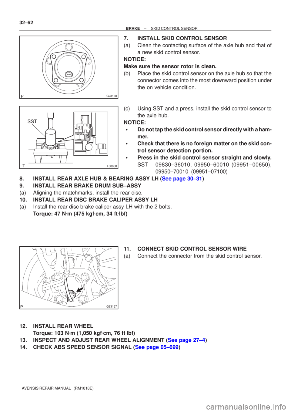
7. INSTALL SKID CONTROL SENSOR
(a) Clean the contacting surface of the axle hub and that of a new skid control sensor.
NOTICE:
Make sure the sensor rotor is clean.
(b) Place the skid control sensor on the axle hub so that the connector comes into the most downward position under
the on vehicle condition.
(c) Using SST and a press, install the skid control sensor to the axle hub.
NOTICE:
�Do not tap the skid control sensor directly with a ham-
mer.
�Check that there is no foreign matter on the skid con-
trol sensor detection portion.
�Press in the skid control sensor straight and slowly.
SST 09830±36010, 09950±60010 (09951±00650), 09950±70010 (09951±07100)
8.INSTALL REAR AXLE HUB & BEARING ASSY LH (See page 30±31)
9. INSTALL REAR BRAKE DRUM SUB±ASSY
(a) Aligning the matchmarks, install the rear disc.
10. INSTALL REAR DISC BRAKE CALIPER ASSY LH
(a) Install the rear disc brake caliper assy LH with the 2 bolts. Torque: 47 N �m (475 kgf �cm, 34 ft �lbf)
11. CONNECT SKID CONTROL SENSOR WIRE
(a) Connect the connector from the skid control sensor.
12. INSTALL REAR WHEEL Torque: 103 N �m (1,050 kgf �cm, 76 ft �lbf)
13.INSPECT AND ADJUST REAR WHEEL ALIGNMENT (See page 27±4)
14.CHECK ABS SPEED SENSOR SIGNAL (See page 05±699)
Page 122 of 1690
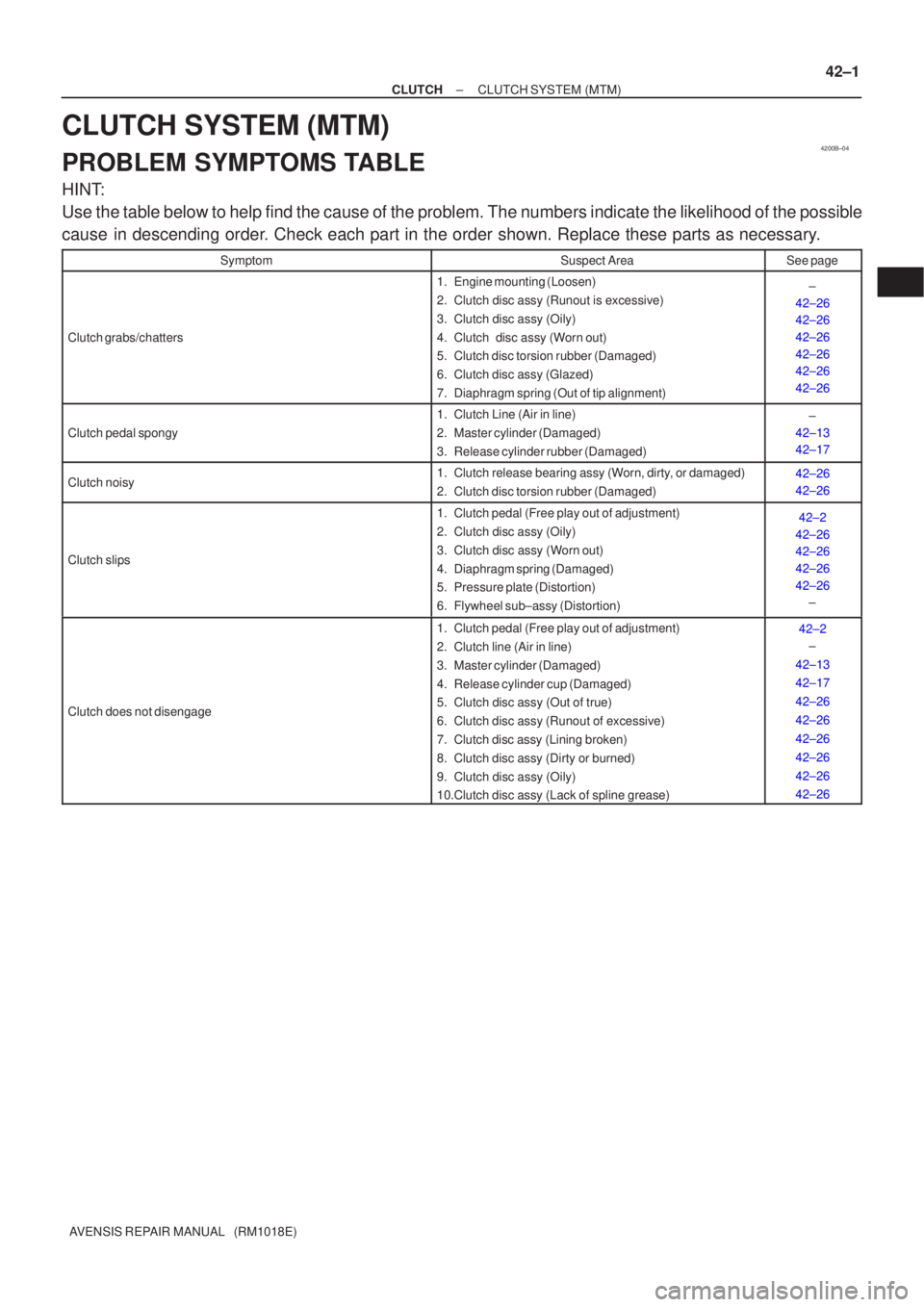
4200B±04
±
CLUTCH CLUTCH SYSTEM (MTM)
42±1
AVENSIS REPAIR MANUAL (RM1018E)
CLUTCH SYSTEM (MTM)
PROBLEM SYMPTOMS TABLE
HINT:
Use the table below to help find the cause of the problem. The numbers indi\
cate the likelihood of the possible
cause in descending order. Check each part in the order shown. Replace these parts as necessary.
SymptomSuspect AreaSee page
Clutch grabs/chatters
1. Engine mounting (Loosen)
2. Clutch disc assy (Runout is excessive)
3. Clutch disc assy (Oily)
4. Clutch disc assy (Worn out)
5. Clutch disc torsion rubber (Damaged)
6. Clutch disc assy (Glazed)
7. Diaphragm spring (Out of tip alignment)±
42±26
42±26
42±26
42±26
42±26
42±26
Clutch pedal spongy
1. Clutch Line (Air in line)
2. Master cylinder (Damaged)
3. Release cylinder rubber (Damaged)±
42±13
42±17
Clutch noisy1. Clutch release bearing assy (Worn, dirty, or damaged)
2. Clutch disc torsion rubber (Damaged)42±26
42±26
Clutch slips
1. Clutch pedal (Free play out of adjustment)
2. Clutch disc assy (Oily)
3. Clutch disc assy (Worn out)
4. Diaphragm spring (Damaged)
5. Pressure plate (Distortion)
6. Flywheel sub±assy (Distortion)42±2
42±26
42±26
42±26
42±26 ±
Clutch does not disengage
1. Clutch pedal (Free play out of adjustment)
2. Clutch line (Air in line)
3. Master cylinder (Damaged)
4. Release cylinder cup (Damaged)
5. Clutch disc assy (Out of true)
6. Clutch disc assy (Runout of excessive)
7. Clutch disc assy (Lining broken)
8. Clutch disc assy (Dirty or burned)
9. Clutch disc assy (Oily)
10.Clutch disc assy (Lack of spline grease)42±2
±
42±13
42±17
42±26
42±26
42±26
42±26
42±26
42±26
Page 123 of 1690
4206H±01
D26321
1ZZ±FE/3ZZ±FE Engine Type:
Flywheel Sub±assyClutch Disc Assy
Release hub grease
N�m (kgf�cm, ft�lbf) : Specified torque
�Non±reusable part
Clutch spline greasex6
Clutch Release
Bearing Assy
Release Bearing
Hub ClipClutch Release
Fork Sub±assy
Clutch Cover Assy
Clutch Release Fork Boot Release Fork Support
37 (375, 27)
19 (194, 14)
± CLUTCHCLUTCH UNIT (MTM)
42±23
AVENSIS REPAIR MANUAL (RM1018E)
CLUTCH UNIT (MTM)
COMPONENTS
Page 124 of 1690
D30056Release hub grease
N�m (kgf�cm, ft�lbf) : Specified torque
�Non±reusable part
Clutch spline grease 1AZ±FSE/1AZ±FE Engine Type:
Flywheel Sub±assy
Clutch Disc Assy
Clutch Release
Fork Sub±assy Clutch Cover AssyRelease Bearing
Hub Clip Clutch Release
Bearing Assy
Release Fork Support
Clutch Release
Fork Boot
48 (480, 35)
19 (194, 14)
x6 42±24
± CLUTCHCLUTCH UNIT (MTM)
AVENSIS REPAIR MANUAL (RM1018E)
Page 125 of 1690
D30057
1CD±FTV Engine Type:
Flywheel Sub±assyClutch Disc Assy
Clutch Release Fork Sub±assy Clutch Cover Assy
Release Bearing
Hub Clip Clutch Release
Bearing Assy
Release Fork Support
Clutch Release
Fork Boot
37 (375, 27)
19 (194, 14)
x6
Release hub grease
N�m (kgf�cm, ft�lbf) : Specified torque
�Non±reusable part
Clutch spline grease
± CLUTCHCLUTCH UNIT (MTM)
42±25
AVENSIS REPAIR MANUAL (RM1018E)