Page 2852 of 4323
B05842
B01044
B00951
LU±10
± LUBRICATIONOIL PUMP
2844 Author�: Date�:
2005 SEQUOIA (RM1146U)
13. REMOVE OIL STRAINER
Remove the 2 bolt, 2 nuts, oil strainer and gasket.
14. REMOVE OIL PUMP
(a) Remove the 8 bolts.
HINT:
Use a 6 mm hexagon wrench for the hexagon head bolt.
(b) Using a screwdriver, remove the oil pump by prying the
portions between the oil pump and cylinder block.
NOTICE:
Be careful not to damage the contact surface of the cylin-
der block and oil pump.
(c) Remove the O±ring from the cylinder block.
Page 2857 of 4323

INSTALLATION
1. INSTALL OIL PUMP
(a) R")
LU0GY-06
B13060
Seal Width
2 - 3 mmA
B
A
B
P21388
New O-Ring
Engage
B00950
A
B C
DE
AAA
- LUBRICATIONOIL PUMP
LU-15
2849 Author�: Date�:
2005 SEQUOIA (RM1146U)
INSTALLATION
1. INSTALL OIL PUMP
(a) Remove any old packing (FIPG) material and be careful
not to drop any oil on the contact surfaces of the oil pump
and cylinder block.
�Using a razor blade and gasket scraper, remove all
the old packing (FIPG) material from the gasket sur-
faces and sealing groove.
�Thoroughly clean all components to remove all the
loose material.
�Using a non-residue solvent, clean both sealing
surfaces.
(b) Apply seal packing to the oil pump as shown in the illustra-
tion.
Seal packing: Part No. 08826-00080 or equivalent
NOTICE:
Avoid applying an excessive amount to the surface. Be par-
ticularly careful near oil passage.
�Install a nozzle that has been cut to a 2 - 3 mm (0.08
- 0.12 in.) opening.
�Parts must be assembled within 3 minutes of ap-
plication. Otherwise the material must be removed
and reapplied.
�Immediately remove nozzle from the tube and rein-
stall cap.
(c) Install a new O-ring to the cylinder block.
(d) Engage the spline teeth of the oil pump drive gear with the
large teeth of the crankshaft, and slide the oil pump on the
crankshaft.
(e) Install the oil pump with the 8 bolts. Uniformly tighten the
bolts in several passes.
Torque:
30.5 N´m (310 kgf´cm, 22 ft´lbf) for 14 mm head
15.5 N´m (160 kgf´cm, 11 ft´lbf) for others
Page 2858 of 4323

HINT:
�Use a 6 mm hexagon wrench for the hexagon head bolt.
�Each bolt length is ind")
B05842
B13061
A
B
Seal Width
2 - 3 mm A
B LU-16
- LUBRICATIONOIL PUMP
2850 Author�: Date�:
2005 SEQUOIA (RM1146U)
HINT:
�Use a 6 mm hexagon wrench for the hexagon head bolt.
�Each bolt length is indicated in the illustration.
Bolt length:
35 mm (1.38 in.) for A of 12 mm head
50 mm (1.97 in.) for B of 12 mm head
106 mm (4.17 in.) for C of 12 mm head
40 mm (1.57 in.) for D of 14 mm head
30 mm (1.18 in.) for E of 6 mm hexagon head
2. INSTALL OIL STRAINER
Install a new gasket and the oil strainer with the 2 bolts and 2
nuts.
Torque: 7.5 N´m (76 kgf´cm, 66 in.´lbf)
3. INSTALL NO.1 OIL PAN
(a) Remove any old packing (FIPG) material and be careful
not to drop any oil on the contact surfaces of the No.1 oil
pan, cylinder block, oil pump and rear oil seal retainer.
�Using a razor blade and gasket scraper, remove all
the old packing (FIPG) material from the gasket sur-
faces and sealing groove.
�Thoroughly clean all components to remove all the
loose material.
�Using a non-residue solvent, clean both sealing
surfaces.
(b) Apply seal packing to the No.1 oil pan as shown in the il-
lustration.
Seal packing: Part No. 08826-00080 or equivalent
�Install a nozzle that has been cut to a 2 - 3 mm (0.08
- 0.12 in.) opening.
�Parts must be assembled within 3 minutes of ap-
plication. Otherwise the material must be removed
and reapplied.
�Immediately remove nozzle from the tube and rein-
stall cap.
Page 2859 of 4323

(c) Temporarily install the No.1 oil pan with the")
B07335
A
B
A
A
A
BBBC
BBBB
C
CC
D
D
B05839
B05845
AB
Seal Width
2 - 3 mm A
B
- LUBRICATIONOIL PUMP
LU-17
2851 Author�: Date�:
2005 SEQUOIA (RM1146U)
(c) Temporarily install the No.1 oil pan with the 18 bolts, stud
bolt and 2 nuts.
HINT:
Each bolt length is indicated in the illustration.
Bolt length:
20 mm (0.79 in.) for A of 10 mm head
25 mm (0.98 in.) for B of 12 mm head
60 mm (2.36 in.) for C of 12 mm head
35 mm (1.38 in.) for D of 10 mm head
(d) Set the No.1 oil pan as shown in the illustration.
NOTICE:
Make sure the clearance between the rear ends of the No.1
oil pan and cylinder block is 0.2 mm (0.008 in.) or less. If the
clearance is more than 0.2 mm (0.008 in.), the No.1 oil pan
will be stretched.
(e) Uniformly tighten the bolts, and nuts in several passes.
Torque:
7.5 N´m (76 kgf´cm, 66 in.´lbf) for 10 mm head
28 N´m (290 kgf´cm, 21 ft´lbf) for 12 mm head
4. INSTALL OIL PAN BAFFLE PLATE
Install the baffle plate with the 7 bolts and 2 nuts.
Torque: 7.5 N´m (76 kgf´cm, 66 in.´lbf)
5. INSTALL NO.2 OIL PAN
(a) Remove any old packing (FIPG) material and be careful
not to drop any oil on the contact surfaces of the No.1 and
No.2 oil pans.
�Using a razor blade and gasket scraper, remove all
the old packing (FIPG) material from the gasket sur-
faces and sealing groove.
�Thoroughly clean all components to remove all the
loose material.
�Using a non-residue solvent, clean both sealing
surfaces.
NOTICE:
Do not use a solvent which will affect the painted surfaces.
(b) Apply seal packing to the No.2 oil pan as shown in the il-
lustration.
Seal packing: Part No. 08826-00080 or equivalent
�Install a nozzle that has been cut to a 3 - 4 mm (0.12
- 0.16 in.) opening.
Page 2860 of 4323

�Parts must be assembled within 3 minutes of ap-
plication. Otherwise the mate")
B05838
B05846
Vinyl Tape
B05837
Push New O-Ring
LU-18
- LUBRICATIONOIL PUMP
2852 Author�: Date�:
2005 SEQUOIA (RM1146U)
�Parts must be assembled within 3 minutes of ap-
plication. Otherwise the material must be removed
and reapplied.
�Immediately remove nozzle from the tube and rein-
stall cap.
(c) Install the No.2 oil pan with the 24 bolts and 2 nuts. Uni-
formly tighten the bolts and nuts in several passes.
Torque: 7.5 N´m (76 kgf´cm, 66 in.´lbf)
6. INSTALL CRANKSHAFT POSITION SENSOR
(See page IG-13)
7. INSTALL OIL FILTER, OIL COOLER AND FILTER
BRACKET ASSEMBLY
(a) Install a new gasket to the oil filter bracket.
(b) Install the oil filter, oil cooler and filter bracket assembly
with the 2 bolts and nut.
Torque: 18 N´m (185 kgf´cm, 13 ft´lbf)
(c) Connect the oil cooler hose to the oil cooler.
(d) Install the clamp.
Turn the clamp clockwise, and install the clamp to the oil
filter bracket.
(e) Install the wire to the clamp with a vinyl tape.
(f) Connect the oil pressure switch connector.
8. INSTALL OIL DIPSTICK GUIDE AND DIPSTICK
(a) Install a new O-ring to the dipstick guide.
(b) Apply soapy water to the O-ring.
(c) Push in the oil dipstick guide end into the guide hole of the
No.1 oil pan.
(d) Install the oil dipstick guide with the bolt.
Torque: 15 N´m, (155 kgf´cm, 11 ft´lbf)
(e) Install the oil dipstick.
9. INSTALL CRANKSHAFT TIMING PULLEY
(See page EM-23)
Page 2886 of 4323
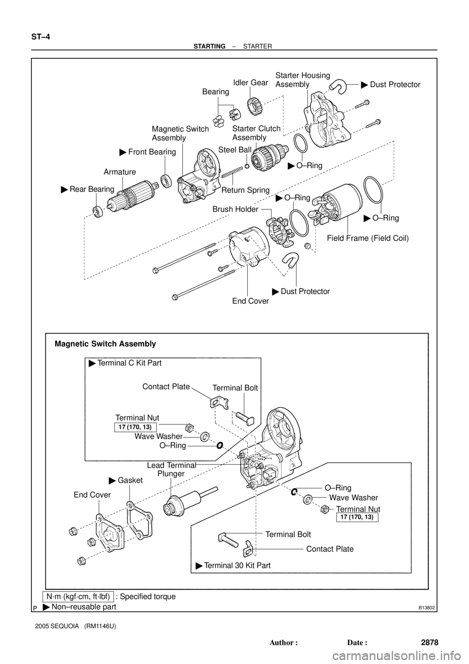
B13802
� O±Ring Idler GearStarter Housing
Assembly
Return SpringStarter Clutch
Assembly
Steel Ball
Contact Plate � Rear BearingArmatureMagnetic Switch
AssemblyBearing
� Front Bearing
� O±Ring
End Cover
Brush Holder
Magnetic Switch Assembly
Terminal Nut
O±Ring Wave WasherTerminal Bolt
� Terminal C Kit Part
Lead Terminal
Plunger
� Gasket
End Cover
Terminal BoltWave Washer O±Ring
Terminal Nut
� Terminal 30 Kit Part
� Non±reusable part
� Dust Protector
� Dust Protector
Field Frame (Field Coil)
17 (170, 13)
17 (170, 13)
N´m (kgf´cm, ft´lbf) : Specified torque� O±Ring
Contact Plate
ST±4
± STARTINGSTARTER
2878 Author�: Date�:
2005 SEQUOIA (RM1146U)
Page 2895 of 4323

(psi)
(kPa) = (psi) x 6.9100 kgf
2 Ram diameter (cm)
(kPa) = (kgf/cm
2) x 98.1 ==
x 3.14 (p)
2
221lbf
2 Ram diameter (in.)
x 3.14 (p)
2
B13044
SST
B1232")
B12323
33 mm20 mm
Contact
Plate
40 mm
(kgf/cm2)
(psi)
(kPa) = (psi) x 6.9100 kgf
2 Ram diameter (cm)
(kPa) = (kgf/cm
2) x 98.1 ==
x 3.14 (p)
2
221lbf
2 Ram diameter (in.)
x 3.14 (p)
2
B13044
SST
B12326
± STARTINGSTARTER
ST±13
2887 Author�: Date�:
2005 SEQUOIA (RM1146U)
(g) Tighten terminal nuts.
(1) Put a wooden block on the contact plate and press
it down with a hand press.
Dimensions of wooden block:
20 x 33 x 40 mm (0.79 x 1.30 x 1.57 in.)
Press force:
981 N (100 kgf, 221 lbf)
NOTICE:
�Check the diameter of the hand press ram. Then cal-
culate the gauge pressure of the press when
981 N (100 kgf, 221 lbf) of force is applied.
Gauge pressure:
�If the contact plate is not pressed down with the spe-
cified pressure, the contact plate may tilt due to coil
deformation or the tightening of the nut.
(2) Using SST, tighten the nuts to the specified torque.
SST 09810±38140
Torque: 17 N´m (170 kgf´cm, 13 ft´lbf)
NOTICE:
If the nut is over tightened, it may cause cracks on the plas-
tic frame.
(h) Clean contact surfaces of the contact plate and the plung-
er.
Clean the contact surfaces of the remaining contact plate
and plunger with a dry shop rag.
(i) Reinstall the magnetic switch end cover.
Install the plunger, the new gasket and the end cover with
the 3 nuts.
Torque: 3.6 N´m (37 kgf´cm, 32 in.´lbf)
Page 2920 of 4323
D13867
AT132±01
OR0004
SST
OR0005
SST
AT±4
± AUTOMATIC TRANSMISSION (A750E, A750F)EXTENSION HOUSING OIL SEAL (A750E)
2912 Author�: Date�:
2005 SEQUOIA (RM1146U)
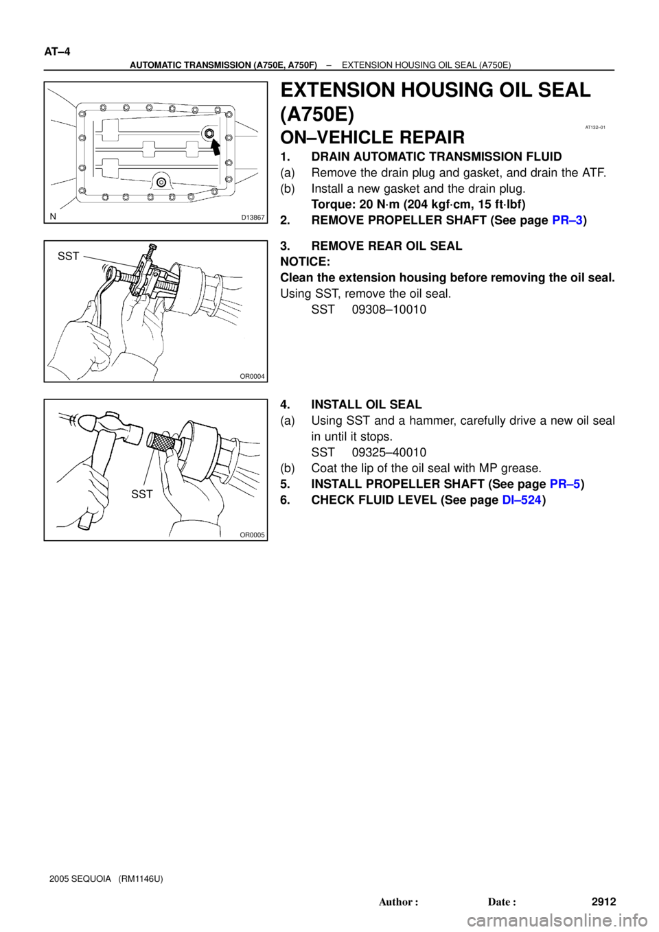
EXTENSION HOUSING OIL SEAL
(A750E)
ON±VEHICLE REPAIR
1. DRAIN AUTOMATIC TRANSMISSION FLUID
(a) Remove the drain plug and gasket, and drain the ATF.
(b) Install a new gasket and the drain plug.
Torque: 20 N´m (204 kgf´cm, 15 ft´lbf)
2. REMOVE PROPELLER SHAFT (See page PR±3)
3. REMOVE REAR OIL SEAL
NOTICE:
Clean the extension housing before removing the oil seal.
Using SST, remove the oil seal.
SST 09308±10010
4. INSTALL OIL SEAL
(a) Using SST and a hammer, carefully drive a new oil seal
in until it stops.
SST 09325±40010
(b) Coat the lip of the oil seal with MP grease.
5. INSTALL PROPELLER SHAFT (See page PR±5)
6. CHECK FLUID LEVEL (See page DI±524)