Page 2608 of 4323

INSPECTION
1. INSPECT TIMING BELT
NOTICE:
�Do not bend, twist or turn the timin")
EM0KX±07
EM3336
NO !
P20079
P20633
± ENGINE MECHANICALTIMING BELT
EM±21
2600 Author�: Date�:
2005 SEQUOIA (RM1146U)
INSPECTION
1. INSPECT TIMING BELT
NOTICE:
�Do not bend, twist or turn the timing belt inside out.
�Do not allow the timing belt to come into contact with
oil, water or steam.
�Do not utilize timing belt tension when installing or re-
moving the mount bolt of the camshaft timing pulley.
If there is any defect, as shown in the illustration, check these
points:
(a) Premature parting
�Check for proper installation.
�Check the timing cover gasket for damage and
proper installation.
(b) If the belt teeth are cracked or damaged, check to see if
either camshaft is locked.
(c) If there is noticeable wear or cracks on the belt face,
check to see if there are nicks on the side of the idler
pulley lock and water pump.
(d) If there is wear or damage on even one side of the belt,
check the belt guide and the alignment of each pulley.
(e) If there is noticeable wear on the belt teeth, check timing
cover for damage and for foreign material on the pulley
teeth.
If necessary, replace the timing belt.
2. INSPECT IDLER PULLEYS
(a) Visually check the seal portion of the idler pulley for oil
leakage.
If leakage is found, replace the idler pulley.
(b) Check that the idler pulley turns smoothly.
If necessary, replace the idler pulley.
3. INSPECT TIMING BELT TENSIONER
(a) Visually check the seal portion of the tensioner for oil leak-
age.
HINT:
If there is only the faintest trace of oil on the seal on the push
rod side, the tensioner is all right.
If leakage is found, replace the tensioner.
Page 2610 of 4323

INSTALLATION
1. INSTALL CRANKSHAFT TIMING PULLEY
(a) Align the timing pul")
EM1WY±01
A04446
SST
Inward
A04447
A04342
± ENGINE MECHANICALTIMING BELT
EM±23
2602 Author�: Date�:
2005 SEQUOIA (RM1146U)
INSTALLATION
1. INSTALL CRANKSHAFT TIMING PULLEY
(a) Align the timing pulley set key with the key groove of the
pulley.
(b) Using SST and a hammer, tap in the timing pulley, facing
the flange side inward.
SST 09223±46011
2. INSTALL NO.1 IDLER PULLEY AND NO.2 IDLER
PULLEY
(a) Apply adhesive 2 or 3 threads of the pivot bolt.
Adhesive:
Part No. 08833±00080, THREE BOND 1344,
LOCTITE 242 or equivalent
(b) Using a 10 mm hexagon wrench, install the plate washer
and No.1 idler pulley with the pivot bolt.
Torque: 34.5 N´m (350 kgf´cm, 25 ft´lbf)
(c) Install the No.2 idler pulley with the bolt.
Torque: 34.5 N´m (350 kgf´cm, 25 ft´lbf)
(d) Check that the No.1 and No.2 idler pulleys moves
smoothly.
3. TEMPORARILY INSTALL TIMING BELT
NOTICE:
The engine should be cold.
(a) Remove any oil or water on the crankshaft pulley, oil
pump pulley, water pump pulley, No.1 idler pulley and
No.2 idler pulley, and keep them clean.
NOTICE:
Only wipe the pulleys; do not use any cleansing agent.
(b) Align the installation mark on the timing belt with the tim-
ing mark of the crankshaft timing pulley.
(c) Install the timing belt on the crankshaft timing pulley, No.1
idler pulley and No.2 idler pulley.
4. INSTALL TIMING BELT COVER SPACER
(a) Install the gasket to the cover spacer.
(b) Install the cover spacer.
Page 2617 of 4323
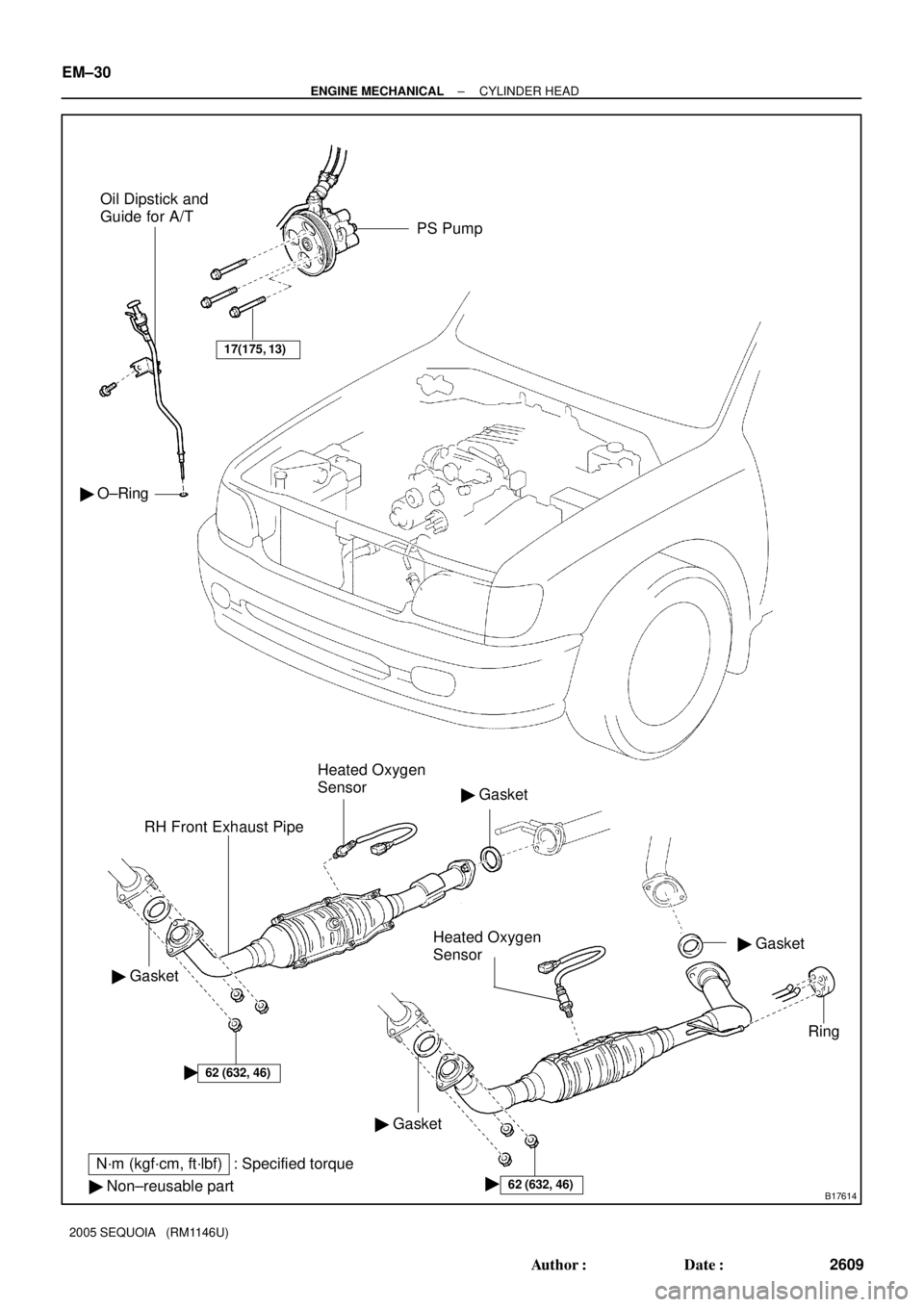
B17614
� GasketRH Front Exhaust Pipe
� Gasket
� Non±reusable part
N´m (kgf´cm, ft´lbf) : Specified torquePS Pump Oil Dipstick and
Guide for A/T
62 (632, 46)�Ring
�
� Gasket
17(175, 13)
62 (632, 46)
Heated Oxygen
Sensor
� Gasket
Heated Oxygen
Sensor
� O±Ring
EM±30
± ENGINE MECHANICALCYLINDER HEAD
2609 Author�: Date�:
2005 SEQUOIA (RM1146U)
Page 2619 of 4323
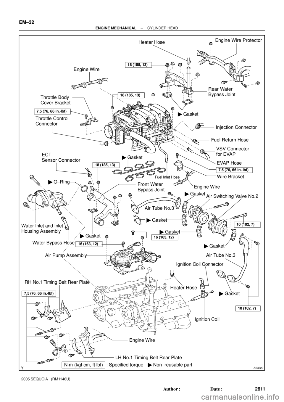
A23320
Rear Water
Bypass JointEngine Wire Protector
� Gasket
Injection Connector
Ignition Coil Connector
Ignition Coil Throttle Control
Connector
ECT
Sensor Connector
Front Water
Bypass Joint
Water Inlet and Inlet
Housing Assembly
Water Bypass Hose
LH No.1 Timing Belt Rear Plate
� Non±reusable partEngine Wire
� Gasket
� O±Ring
Engine WireHeater Hose
Throttle Body
Cover Bracket
VSV Connector
for EVAP Fuel Return Hose
Engine Wire
EVAP Hose
Heater Hose
Wire BracketFuel Inlet Hose
� Gasket
RH No.1 Timing Belt Rear Plate
� GasketAir Switching Valve No.2
Air Tube No.3
Air Tube No.3
� Gasket
N´m (kgf´cm, ft´lbf) : Specified torque� Gasket
18 (185, 13)
18 (185, 13)
18 (185, 13)
7.5 (76, 66 in.´lbf)
7.5 (76, 66 in.´lbf)
� Gasket
� Gasket
7.5 (76, 66 in.´lbf)
Air Pump Assembly
16 (163, 12)
10 (102, 7)
10 (102, 7)
16 (163, 12)
EM±32
± ENGINE MECHANICALCYLINDER HEAD
2611 Author�: Date�:
2005 SEQUOIA (RM1146U)
Page 2621 of 4323
 : Specified torque Camshaft Timing
Oil Control Valve
(Bank 2) Connector
RH Cylinder
Head Cover
Engine
Wire
Clamp
Bracket� Spark Plug Tube
Gasket")
A23322� Non±reusable part
N´m (kgf´cm, ft´lbf) : Specified torque Camshaft Timing
Oil Control Valve
(Bank 2) Connector
RH Cylinder
Head Cover
Engine
Wire
Clamp
Bracket� Spark Plug Tube
Gasket
Seal
Washer LH Cylinder
Head Cover
RH Intake
Camshaft
(with Timing
Tube)
Semi±circular Plug
Ground Strap
Ground WireEngine Wire
Clamp
x 9
Camshaft
Timing Oil
Control Valve
(Bank 1)
Camshaft Timing
Oil Control Valve
(Bank 2)
Front
Bearing Cap
Spark PlugGasket
Oil
Feed
Pipe
� Seal
Washer
Ground Wire
Camshaft Bearing Cap
16 (160, 12)� O±Ring
LH Exhaust
Camshaft
Camshaft
Housing Plug
Semi±circular
Plug
Strainer
� O±Ring
Gasket
�
LH Intake Camshaft
(with Timing Tube)
RH Exhaust
Camshaft
Camshaft
Housing
Plug
Engine Wire
Bracket
� LH Cylinder Head GasketLH Cylinder Head and
Exhaust Manifold Assembly
Air±fuel Ratio Sensor
(Bank 1 Sensor 1) Connector
RH Cylinder
Head Gasket
Engine
Wire
7.5 (76, 66 in.´lbf)
7.5 (76, 66 in.´lbf)
Seal
Washerx 9
x 10
�Camshaft Timing
Oil Control Valve
(Bank 1) Connector
Air±fuel Ratio Sensor
(Bank 2 Sensor 1)
Connector
Strainer
1st 40 (408, 30)
2nd Turn 90°
3rd
Turn 90° See page EM±60
Front
Bearing Cap
6.0 (600, 53 in.´lbf)
6.0 (600, 53 in.´lbf)
EM±34
± ENGINE MECHANICALCYLINDER HEAD
2613 Author�: Date�:
2005 SEQUOIA (RM1146U)
Page 2622 of 4323
A23372� Non±reusable part
N´m (kgf´cm, ft´lbf) : Specified torqueCamshaft Drive Gear
Camshaft Timing Tube
Seal WasherIntake Camshaft
Exhaust Camshaft
� Camshaft Oil Seal
Camshaft Gear Spring
Camshaft Driven Sub±gear
Snap Ring Wave Washer Screw Plug
15 (150, 11)
7.5 (80, 66 in.´lbf)
Camshaft Driven Main Gear78 (790, 58)
A23323
Heat Insulator LH Exhaust Manifold
44 (450, 32)
Heat Insulator
44 (450, 32)
� Gasket RH Cylinder HeadValve Lifter
� Oil Seal Spring SeatValve SpringSpring RetainerAdjust Shim
Keeper
� Valve Guide Bushing
Valve
RH Exhaust Manifold
� Gasket LH Cylinder Head
� Non±reusable part
N´m (kgf´cm, ft´lbf) : Specified torque
�
�
7.5 (76, 66 in.´lbf)
7.5 (76, 66 in.´lbf)
± ENGINE MECHANICALCYLINDER HEAD
EM±35
2614 Author�: Date�:
2005 SEQUOIA (RM1146U)
Page 2633 of 4323

INSPECTION
1. CLEAN TOP SURFACES OF PISTONS AND CYL-
INDER BLOCK
(a)")
EM1X1±01
A03194
A03193
EM6323
EM6324
P21861
EM±46
± ENGINE MECHANICALCYLINDER HEAD
2625 Author�: Date�:
2005 SEQUOIA (RM1146U)
INSPECTION
1. CLEAN TOP SURFACES OF PISTONS AND CYL-
INDER BLOCK
(a) Turn the crankshaft, and bring each piston to top dead
center (TDC). Using a gasket scraper, remove all the car-
bon from the piston top surface.
(b) Using a surface contacting gasket scraper, remove all the
gasket materials from the cylinder block.
(c) Using compressed air, blow carbon and oil from the bolt
holes.
CAUTION:
Protect your eyes when using high pressure compressed
air.
2. REMOVE GASKET MATERIAL
Using a gasket scraper, remove all the gasket material from the
cylinder block contact surface.
NOTICE:
Be careful not to scratch the surface contacting the cylin-
der block.
3. CLEAN COMBUSTION CHAMBERS
Using a wire brush, remove all the carbon from the combustion
chambers.
NOTICE:
Be careful not to scratch the surface contacting the cylin-
der block.
4. CLEAN VALVE GUIDE BUSHINGS
Using a valve guide bushing brush and solvent, clean all the
guide bushings.
Page 2635 of 4323

9. CLEAN VALVES
(a) Using a gasket scraper, chip off any carbon fr")
EM0580
A04087A04091A04236
Z00052
Z00054
44.5° EM±48
± ENGINE MECHANICALCYLINDER HEAD
2627 Author�: Date�:
2005 SEQUOIA (RM1146U)
9. CLEAN VALVES
(a) Using a gasket scraper, chip off any carbon from the valve
head.
(b) Using a wire brush, thoroughly clean the valve.
10. INSPECT VALVE STEMS AND GUIDE BUSHINGS
(a) Using a caliper gauge, measure the inside diameter of the
guide bushing.
Bushing inside diameter:
5.510 to 5.530 mm (0.2169 to 0.2177 in.)
(b) Using a micrometer, measure the diameter of the valve
stem.
Valve stem diameter:
Intake5.470 to 5.485 mm (0.2154 to 0.2159 in.)
Exhaust5.465 to 5.480 mm (0.2152 to 0.2157 in.)
(c) Subtract the valve stem diameter measurement from the
guide bushing inside diameter measurement.
Standard oil clearance:
Intake0.025 to 0.060 mm (0.0010 to 0.0024 in.)
Exhaust0.030 to 0.065 mm (0.0012 to 0.0026 in.)
Maximum oil clearance:
Intake0.08 mm (0.0031 in.)
Exhaust0.10 mm (0.0039 in.)
If the clearance is greater than maximum, replace the valve and
guide bushing. (See page EM±56)
11. INSPECT AND GRIND VALVES
(a) Grind the valve enough to remove pits and carbon.
(b) Check that the valve is ground to the correct valve face
angle.
Valve face angle: 44.5°