Page 2923 of 4323
ATF TEMPERATURE SENSOR
AT±7
2915 Author�: Date�:
2005 SEQUOI")
D13867
AT134±01
D12704
Orange
Blue
Clamp
ClampBolt
Bolt
D12739
D12704
Orange
Blue
Clamp
Clamp
A B
± AUTOMATIC TRANSMISSION (A750E, A750F)ATF TEMPERATURE SENSOR
AT±7
2915 Author�: Date�:
2005 SEQUOIA (RM1146U)
ATF TEMPERATURE SENSOR
ON±VEHICLE REPAIR
1. DRAIN AUTOMATIC TRANSMISSION FLUID
(a) Remove the drain plug and gasket, and drain the ATF.
(b) Install a new gasket and the drain plug.
Torque: 20 N´m (204 kgf´cm, 15 ft´lbf)
2. REMOVE OIL PAN (See page AT±10)
3. REMOVE OIL STRAINER (See page AT±10)
4. REMOVE ATF TEMPERATURE SENSOR
(a) Disconnect the 7 solenoid valve connectors.
(b) Remove the 2 bolts, clamps and ATF temperature sen-
sors.
(c) Disconnect the transmission wire connector.
(d) Remove the bolt and the transmission wire harness.
5. INSTALL ATF TEMPERATURE SENSOR
(a) Install the transmission wire harness.
(b) Install the bolt.
Torque: 5.4 N´m (55 kgf´cm, 48 in.´lbf)
(c) Connect the transmission wire connector.
(d) Connect the 7 solenoid valve connectors.
(e) Install the 2 ATF temperature sensors and clamps to the
valve body with the 2 bolts.
HINT:
In order to install the ATF temperature sensors properly, check
the wire harness color prior to installation.
Torque:
A: 11 N´m (112 kgf´cm, 8 ft´lbf)
B: 10 N´m (100 kgf´cm, 7 ft´lbf)
Bolt length:
Bolt A: 36 mm (1.42 in.)
Bolt B: 12 mm (0.47 in.)
Sensor wire harness:
Wire harnessColor
for linear controlOrange
for oil temp. warning lampBlue
6. INSTALL OIL STRAINER (See page AT±10)
Page 2924 of 4323
D13866
AT±8
± AUTOMATIC TRANSMISSION (A750E, A750F)ATF TEMPERATURE SENSOR
2916 Author�: Date�:
2005 SEQUOIA (RM1146U)
7. INSTALL OIL PAN
HINT:
Remove any packing material, and be careful not to spill oil on
the contacting surfaces of the transmission case and the oil
pan.
Using a new gasket, install the oil pan with the 20 bolts.
Torque: 4.4 N´m (45 kgf´cm, 39 in´lbf)
8. FILL WITH ATF AND CHECK ATF LEVEL
(a) Remove the refill plug (See page DI±524).
(b) Fill with new fluid through the refill hole.
Fluid type: Toyota genuine ATF WS
Page 2926 of 4323
VALVE BODY ASSEMBLY
2918 Author�: Date�:
2005 SEQUOIA (RM1146U)
VALVE BOD")
D13867
AT136±01
D13866
AT0103
D12703
D12704
Orange
Blue
Clamp
ClampBolt
Bolt AT±10
± AUTOMATIC TRANSMISSION (A750E, A750F)VALVE BODY ASSEMBLY
2918 Author�: Date�:
2005 SEQUOIA (RM1146U)
VALVE BODY ASSEMBLY
ON±VEHICLE REPAIR
1. DRAIN AUTOMATIC TRANSMISSION FLUID
(a) Remove the drain plug and gasket, and drain the ATF.
(b) Install a new gasket and the drain plug.
Torque: 20 N´m (204 kgf´cm, 15 ft´lbf)
2. REMOVE OIL PAN
NOTICE:
Some fluid will remain in the oil pan.
(a) Remove the 20 bolts.
(b) Remove the oil pan gasket.
3. EXAMINE PARTICLES IN PAN
Remove the magnets and use them to collect any steel par-
ticles. Carefully look at the foreign matter and particles in the
pan and on the magnets to anticipate the type of wear you will
find in the transmission.
Steel (magnetic) ... bearing, gear and clutch plate wear
Brass (non±magnetic) ... bushing wear
4. REMOVE OIL STRAINER
Remove the 4 bolts, the oil strainer and the O±ring.
NOTICE:
Be careful as some fluid will come out with the oil strainer.
5. REMOVE ATF TEMPERATURE SENSOR
(a) Disconnect the 7 solenoid valve connectors.
(b) Remove the 2 bolts, clamps and ATF temperature sen-
sors.
Page 2928 of 4323
VALVE BODY ASSEMBLY
2920 Author�: Date�:
2005 SEQUOIA (RM1146U)
(b) Install the 19 bolts and th")
D12705
D12704
Orange
Blue
Clamp
Clamp
A B
D12703
D13866
AT±12
± AUTOMATIC TRANSMISSION (A750E, A750F)VALVE BODY ASSEMBLY
2920 Author�: Date�:
2005 SEQUOIA (RM1146U)
(b) Install the 19 bolts and the valve body.
Torque: 11 N´m (112 kgf´cm, 8 ft´lbf)
Bolt length:
Bolt A: 25 mm (0.98 in.)
Bolt B: 36 mm (1.42 in.)
10. INSTALL TEMPERATURE SENSOR
(a) Connect the 7 solenoid valve connectors.
(b) Install the 2 temperature sensors and clamps to the valve
body with the 2 bolts.
HINT:
In order to install the ATF temperature sensors properly, check
the wire harness color prior to installation.
Torque:
A: 11 N´m (112 kgf´cm, 8 ft´lbf)
B: 10 N´m (100 kgf´cm, 7 ft´lbf)
Bolt length:
Bolt A: 36 mm (1.42 in.)
Bolt B: 12 mm (0.47 in.)
Sensor wire harness:
Wire harnessColor
for linear controlOrange
for oil temp. warning lampBlue
11. INSTALL OIL STRAINER
(a) Install a new O±ring.
(b) Install the oil strainer with the 4 bolts.
Torque: 10 N´m (100 kgf´cm, 7 ft´lbf)
12. INSTALL OIL PAN
HINT:
Remove any packing material, and be careful not to spill oil on
the contacting surfaces of the transmission case and the oil
pan.
Using a new gasket, install the oil pan with the 20 bolts.
Torque: 4.4 N´m (45 kgf´cm, 39 in´lbf)
Page 2939 of 4323
AT13E±01
D13873
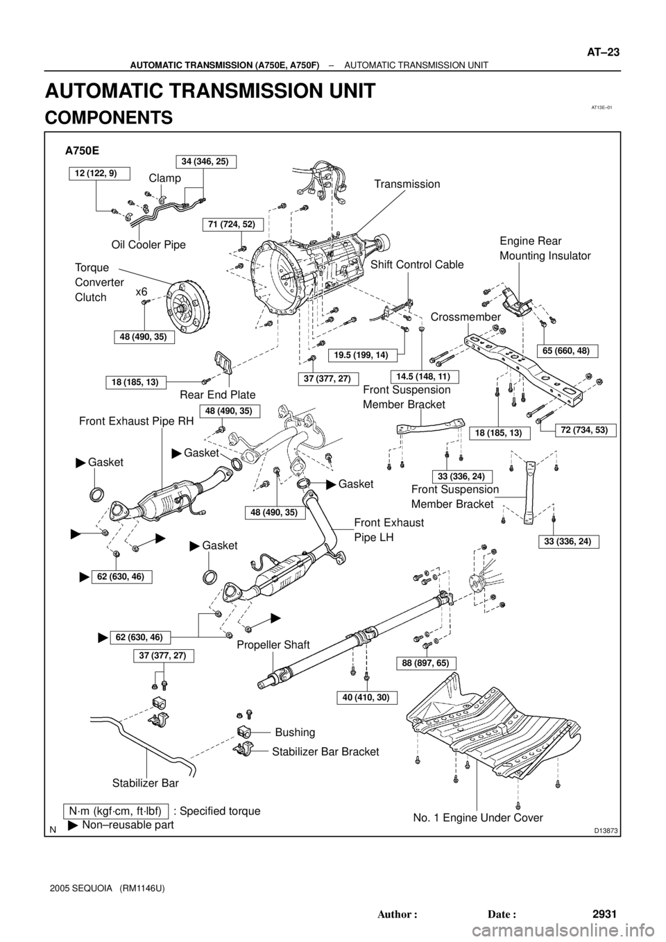
A750E
Clamp
Oil Cooler Pipe34 (346, 25)
Torque
Converter
Clutchx6
Transmission
48 (490, 35)
71 (724, 52)
Front Exhaust Pipe RH
N´m (kgf´cm, ft´lbf) : Specified torque
�Non±reusable part
37 (377, 27)
Stabilizer BarBushing
Stabilizer Bar Bracket
No. 1 Engine Under Cover
40 (410, 30)
88 (897, 65)
18 (185, 13)
CrossmemberEngine Rear
Mounting Insulator
Shift Control Cable
37 (377, 27)
Gasket �
Front Exhaust
Pipe LH
Rear End Plate
18 (185, 13)
Gasket �
�62 (630, 46)
� �
62 (630, 46)
�
� Gasket
Propeller Shaft
19.5 (199, 14)
14.5 (148, 11)
65 (660, 48)
72 (734, 53)
33 (336, 24)
33 (336, 24)
�
� Gasket
48 (490, 35)
Front Suspension
Member Bracket Front Suspension
Member Bracket
12 (122, 9)
48 (490, 35)
± AUTOMATIC TRANSMISSION (A750E, A750F)AUTOMATIC TRANSMISSION UNIT
AT±23
2931 Author�: Date�:
2005 SEQUOIA (RM1146U)
AUTOMATIC TRANSMISSION UNIT
COMPONENTS
Page 2940 of 4323
D13874
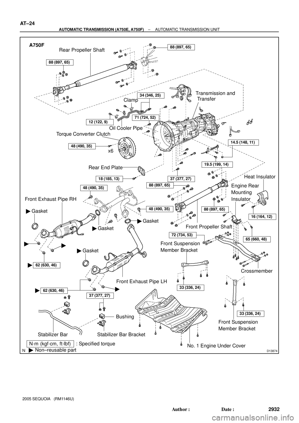
A750F
N´m (kgf´cm, ft´lbf) : Specified torque
�Non±reusable part
37 (377, 27)
Stabilizer Bar
Bushing
Stabilizer Bar Bracket
No. 1 Engine Under Cover
18 (185, 13)
Rear End Plate
Torque Converter Clutch
x6
48 (490, 35)
Oil Cooler Pipe
34 (346, 25)
Gasket �
Front Exhaust Pipe RH
Gasket �
� Gasket
37 (377, 27)
Crossmember
Engine Rear
Mounting
Insulator
19.5 (199, 14)
14.5 (148, 11)
Transmission and
Transfer
88 (897, 65)
Rear Propeller Shaft88 (897, 65)
Front Propeller Shaft
Heat Insulator
Front Exhaust Pipe LH
Clamp
71 (724, 52)
� Gasket
48 (490, 35)
16 (164, 12)
65 (660, 48)
88 (897, 65)
88 (897, 65)
72 (734, 53)
Front Suspension
Member Bracket
33 (336, 24)
Front Suspension
Member Bracket
33 (336, 24)
��
�62 (630, 46)
�62 (630, 46)�
12 (122, 9)
48 (490, 35)
AT±24
± AUTOMATIC TRANSMISSION (A750E, A750F)AUTOMATIC TRANSMISSION UNIT
2932 Author�: Date�:
2005 SEQUOIA (RM1146U)
Page 2948 of 4323

TROUBLESHOOTING
PROBLEM SYMPTOMS TABLE
Use the table below to help find the cause of the problem. The numbers i")
TR04H±04
TR±2
± TRANSFERTROUBLESHOOTING
2940 Author�: Date�:
2005 SEQUOIA (RM1146U)
TROUBLESHOOTING
PROBLEM SYMPTOMS TABLE
Use the table below to help find the cause of the problem. The numbers indicate the priority of the likely cause
of the problem. Check each part in order. If necessary, replace these parts.
SymptomSuspected AreaSee page
Noise
1. Oil (Level low)
2. Oil (Wrong)
3. Transfer faultyTR±5
TR±5
TR±7
Oil leakage
1. Oil (Level too high)
2. Gasket (Damaged)
3. Oil seal (Worn or damaged)
4. O±ring (Worn or damaged)TR±5
TR±7
TR±16
TR±7
Tight corner brakingCenter differential or transfer faultyTR±7
Shift from 2WD (H) to 4WD (H) impossible
1. 4WD fuse
2. Wire harness
3. Vehicle speed sensor
4. 2WD/4HI switch
5. 4WD indicator light
6. Actuator assembly
7. A.D.D. control system
8. 4WD control ECU
9. Transfer assembly±
±
BE±55
TR±39
TR±39
TR±39
SA±61
TR±39
TR±3
Shift from 2WD (H) to 4WD (L4) impossible
1. 4LO switch
2. Wire harness
3. 4WD control ECUTR±39
±
TR±39
Shift from 4WD (H) to 4WD (L4) impossible
1. 4LO switch
2. Wire harness
3. 4WD control ECUTR±9
±
TR±39
Shift from 4WD (H) to 2WD (H) impossible
1. 4WD fuse
2. Wire harness
3. 4WD indicator light
4. Actuator assembly
5. A.D.D. control system
6. 4WD control ECU
7. Transfer assembly±
±
TR±39
TR±39
SA±61
TR±39
TR±3
Shift from 4WD (L4) to 2WD (H) impossible
1. 2WD/4HI switch
2. Wire harness
3. 4WD control ECUTR±39
±
TR±39
Shift from 4WD (L4) to 4WD (H) impossible
1. 2WD/4HI switch
2. Wire harness
3. 4WD control ECUTR±39
±
TR±39
Page 2951 of 4323

± TRANSFERTRANSFER UNIT
TR±5
2943 Author�: Date�:
2005 SEQUOIA (RM1146U)
INSTALLATION
1. INSTALL TRANSFER
Raise the transfer and install it to t")
TR0DE±01
F19237
F19338
0 to 5 mm
(0 to 0.1968 in.)
± TRANSFERTRANSFER UNIT
TR±5
2943 Author�: Date�:
2005 SEQUOIA (RM1146U)
INSTALLATION
1. INSTALL TRANSFER
Raise the transfer and install it to the transmission with the 8
transfer mounting bolts.
Torque: 24 N´m (245 kgf´cm, 18 ft´lbf)
NOTICE:
Take care not to damage the lip of the transfer rear oil seal
with the transfer input shaft.
2. CONNECT VEHICLE SPEED SENSOR AND TRANS-
FER ACTUATOR CONNECTORS
3. INSTALL ENGINE REAR MOUNTING
Install the engine rear mounting to the transfer with the 4 bolts.
Torque: 65 N´m (660 kgf´cm, 48 ft´lbf)
4. INSTALL CROSS MEMBER
(a) Install the cross member with the 4 bolts and nuts.
Torque: 72 N´m (730 kgf´cm, 53 ft´lbf)
(b) Install the 4 set bolts of the engine rear mounting.
Torque: 18 N´m (185 kgf´cm, 13 ft´lbf)
(c) Remove the transmission jacks.
(d) Install the heat insulator with the 2 bolts.
Torque: 16 N´m (164 kgf´cm, 12 ft´lbf)
5. INSTALL FRONT AND REAR PROPELLER SHAFTS
(See page PR±9)
6. INSTALL LH AND RH FRONT EXHAUST PIPES
(See page EM±128)
7. INSTALL FRONT SUSPENSION MEMBER BRACKET
Install the 2 front suspension member brackets with the 8 bolts.
Torque: 33 N´m (336 kgf´cm, 24 ft´lbf)
8. FILL WITH TRANSFER OIL
(a) Remove the filler plug and gasket.
(b) Fill with transfer oil.
Oil grade: API GL±4 or GL±5
Viscosity: SAE 75W±90
Capacity: 1.4 liters (1.5 US qts, 1.2 lmp.qts)
NOTICE:
�When supplying oil, pour it slowly.
�Supply oil several times at several minute intervals.
HINT:
The oil level must be within 0 to 5 mm (0 to 0.1968 in.) down from
the lowest end of the hole for the filler plug.
(c) After leaving it for 5 minutes, check the oil level again.
(d) Install the filler plug with a new gasket.
Torque: 37 N´m (377 kgf´cm, 27 ft´lbf)