Page 2645 of 4323

A03212
Protrusion
A05710
SST
A05711
(1)(2)(3)(4)
EM±58
± ENGINE MECHANICALCYLINDER HEAD
2637 Author�: Date�:
2005 SEQUOIA (RM1146U)
REASSEMBLY
HINT:
�Tho")
EM0L4±09
P08885
Adhesive
15 mm (0.59 in.)
A03212
Protrusion
A05710
SST
A05711
(1)(2)(3)(4)
EM±58
± ENGINE MECHANICALCYLINDER HEAD
2637 Author�: Date�:
2005 SEQUOIA (RM1146U)
REASSEMBLY
HINT:
�Thoroughly clean all parts to be assembled.
�Before installing the parts, apply fresh engine oil to all slid-
ing and rotating surfaces.
�Replace all gaskets and oil seals with new ones.
1. INSTALL SPARK PLUG TUBES
HINT:
When using a new cylinder head, spark plug tubes must be
installed.
(a) Apply adhesive to the end of the spark plug tube.
Adhesive:
Part No. 08833±00070, THREE BOND 1324
or equivalent
(b) Using a wooden block and hammer, tap in a new spark
tube until there is 40.9 ± 42.1 mm (1.610 ± 1.658 in.) pro-
truding from the camshaft bearing cap installation surface
of the cylinder head.
NOTICE:
Avoid tapping a new spark plug tube too far for measuring
the amount of the protrusion while tapping.
2. INSTALL VALVES
(a) Using SST, push in a new oil seal.
SST 09201±41020
(b) Install the valve (1), spring seat (2), valve spring (3) and
spring retainer (4).
Page 2648 of 4323

A23352
A05563
RH Cylinder Head
LH Cylinder Head 2UR
2UL
B02642B02644A04229
RH Bank
LH Bank
1 79
4
6
5
3
10
8
27
96
5
3
10
8
2
1
4
± ENGINE MECHANICALCYLINDER HEAD
EM±61
2640 Author�: Date�:
2005 SEQUOIA (RM1146U)
(c) Install the heat insulator with the 4 bolts.
Torque: 7.5 N´m (76 kgf´cm, 66 in.´lbf)
3. PLACE CYLINDER HEADS ON CYLINDER BLOCK
(a) Place 2 new cylinder head gaskets in the positions on the
cylinder block.
HINT:
On the rear side of the cylinder head gasket are marked to dis-
tinguish the LH and RH banks, a º2URº mark for the RH bank
and a º2ULº mark for the LH bank.
NOTICE:
Be careful of the installation direction.
(b) Place the 2 cylinder heads in the positions on the cylinder
head gaskets.
4. INSTALL CYLINDER HEAD BOLTS
HINT:
�The cylinder head bolts are tightened in 2 progressive
steps (steps (c) and (e)).
�If any cylinder head bolt is broken or deformed, replace
it.
(a) Apply a light coat of engine oil to the threads and under
the heads of the cylinder head bolts.
(b) Install the plate washer to the cylinder head bolt.
(c) Install and uniformly tighten the 10 cylinder head bolts on
one side of the cylinder head in several steps in the se-
quence shown, then perform the same procedure to the
other side as shown.
Torque: 40 N´m (408 kgf´cm, 30 ft´lbf)
If any of the cylinder head bolts does not meet the torque speci-
fication, replace the cylinder head bolt.
Page 2652 of 4323

(4) Install the camshaft housing plug to the cylinder
head as")
A23355
A16831
Seal Packing
Seal Width
1.5 mm
A23356
± ENGINE MECHANICALCYLINDER HEAD
EM±65
2644 Author�: Date�:
2005 SEQUOIA (RM1146U)
(4) Install the camshaft housing plug to the cylinder
head as shown in the illustration.
(5) Install the strainer to the cylinder head.
NOTICE:
Be careful of the installation direction.
(6) Apply seal packing to the front bearing cap.
�Remove any old packing material (FIPG) and
be careful not to drop any oil on the contact
surfaces of the bearing cap and cylinder
head.
Using a razor blade and gasket scraper, re-
move all the old packing material (FIPG) from
the gasket surfaces and groove.
Thoroughly clean all components to remove
all the loose material.
Using a non±residue solvent, clean both
sealing surfaces.
�Apply seal packing to the bearing cap as
shown in the illustration.
Install a nozzle that has been cut to a 1.5 mm
(0.059 in.) opening.
Parts must be assembled within 5 minutes of
application. Otherwise the material must be
removed and reapplied.
Immediately remove the nozzle from the tube
and reinstall cap.
Seal packing: Part No. 08826±00080 or equivalent
NOTICE:
Do not apply seal packing to the front bearing cap grooves.
(7) Install the front bearing cap.
HINT:
Installing the front bearing cap will determine the thrust portion
of the camshaft.
(8) Install the other bearing caps in the sequence
shown with the arrow mark facing forward.
Page 2655 of 4323

(7) Apply seal packing to the front bearing cap.
�Remove")
A16832
Seal Packing
Seal Width
1.5 mm
A23360
A23361
Push EM±68
± ENGINE MECHANICALCYLINDER HEAD
2647 Author�: Date�:
2005 SEQUOIA (RM1146U)
(7) Apply seal packing to the front bearing cap.
�Remove any old packing material (FIPG) and
be careful not to drop any oil on the contact
surfaces of the bearing cap and cylinder
head.
Using a razor blade and gasket scraper, re-
move all the old packing material (FIPG) from
the gasket surfaces and groove.
Thoroughly clean all components to remove
all the loose material.
Using a non±residue solvent, clean both
sealing surfaces.
�Apply seal packing to the bearing cap as
shown in the illustration.
Install a nozzle that has been cut to a 1.5 mm
(0.059 in.) opening.
Parts must be assembled within 5 minutes of
application. Otherwise the material must be
removed and reapplied.
Immediately remove the nozzle from the tube
and reinstall cap.
Seal packing: Part No. 08826±00080 or equivalent
NOTICE:
Do not apply seal packing to the front bearing cap grooves.
(8) Install the front bearing cap.
HINT:
Installing the front bearing cap will determine the thrust portion
of the camshaft.
(9) Install the other bearing caps in the sequence
shown with the arrow mark facing forward.
(10) Push in the camshaft oil seal.
Page 2658 of 4323

(c) Install the")
A04015
Wire
Clamp
Bracket
A23333
Rear Water Bypass Joint
A23332
Front Water Bypass Joint
A23331
± ENGINE MECHANICALCYLINDER HEAD
EM±71
2650 Author�: Date�:
2005 SEQUOIA (RM1146U)
(c) Install the gasket to the cylinder head cover.
(d) Install the seal washer to the bolt.
(e) Install the cylinder head cover with the 9 bolts. Uniformly
tighten the bolts in several steps. Install the 2 cylinder
head covers.
Torque: 6.0 N´m (60 kgf´cm, 53 in.´lbf)
(f) Install the wire clamp bracket on the engine wire to the
camshaft bearing cap.
14. INSTALL ENGINE HANGERS
Torque: 37 N´m (380 kgf´cm, 27 ft´lbf)
15. INSTALL VVT SENSORS (See page SF±77)
16. INSTALL OIL DIPSTICK AND GUIDE FOR ENGINE
17. INSTALL OIL DIPSTICK AND GUIDE FOR A/T
18. INSTALL IGNITION COILS (See page IG±6)
19. INSTALL REAR WATER BYPASS JOINT
(a) Install 2 new gaskets to the cylinder head.
(b) Install the the water bypass joint with the 4 nuts to the cyl-
inder heads. Alternately tighten the nuts.
Torque: 18 N´m (185 kgf´cm, 13 ft´lbf)
20. INSTALL NO.2 AIR SWITCHING VALVES
(See page EC±26)
21. INSTALL AIR PUMP ASSEMBLY (See page EC±26)
22. INSTALL FRONT WATER BYPASS JOINT
Install 2 new gaskets and the water bypass joint with the 4 nuts.
Alternately tighten the nuts.
Torque: 18 N´m (185 kgf´cm, 13 ft´lbf)
23. INSTALL WATER INLET AND INLET HOUSING AS-
SEMBLY (See page CO±8)
24. ASSEMBLE INTAKE MANIFOLDS
(a) Install the 2 delivery pipes and 8 injectors (see page
SF±31).
(b) Install 2 new gaskets and fuel pulsation damper.
(c) Install a new O±ing and fuel pressure regulator with the
2 bolts.
(d) Install the fuel return pipe to the intake manifold with the
3 bolts.
(e) Connect the fuel return hose to the fuel pressure regula-
tor.
Page 2677 of 4323
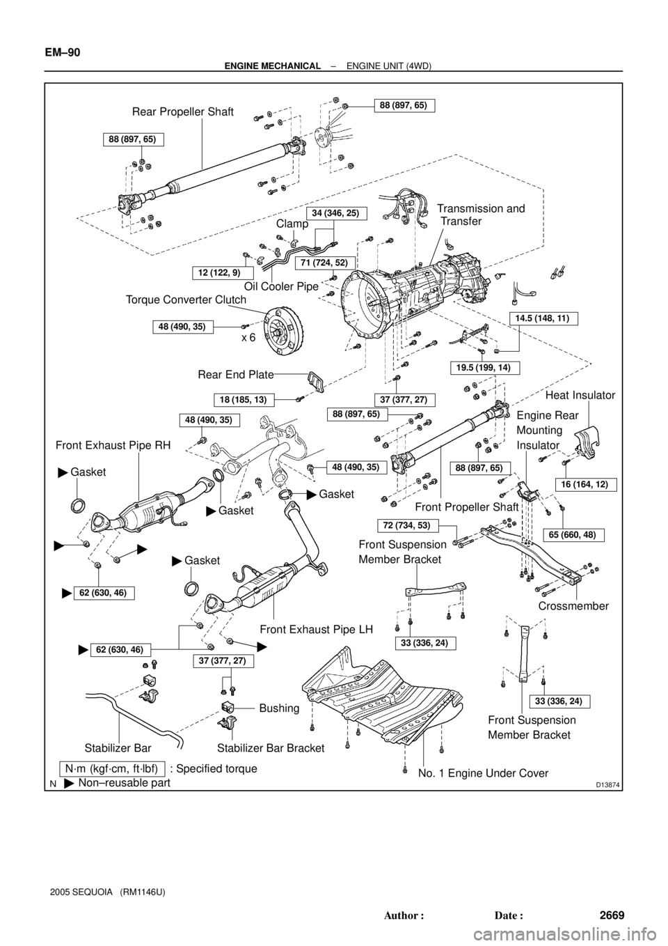
D13874
N´m (kgf´cm, ft´lbf) : Specified torque
�Non±reusable part
37 (377, 27)
Stabilizer Bar
Bushing
Stabilizer Bar Bracket
No. 1 Engine Under Cover
18 (185, 13)
Rear End Plate
Torque Converter Clutch
x 6
48 (490, 35)
Oil Cooler Pipe
34 (346, 25)
Gasket �
Front Exhaust Pipe RH
48 (490, 35)
Gasket �
� Gasket
37 (377, 27)
Crossmember
Engine Rear
Mounting
Insulator
19.5 (199, 14)
14.5 (148, 11)
Transmission and
Transfer
88 (897, 65)
Rear Propeller Shaft88 (897, 65)
Front Propeller Shaft
Heat Insulator
Front Exhaust Pipe LH
Clamp
71 (724, 52)
� Gasket
48 (490, 35)
16 (164, 12)
65 (660, 48)
88 (897, 65)
88 (897, 65)
72 (734, 53)
Front Suspension
Member Bracket
33 (336, 24)
Front Suspension
Member Bracket
33 (336, 24)
��
�62 (630, 46)
�62 (630, 46)�
12 (122, 9)
EM±90
± ENGINE MECHANICALENGINE UNIT (4WD)
2669 Author�: Date�:
2005 SEQUOIA (RM1146U)
Page 2686 of 4323
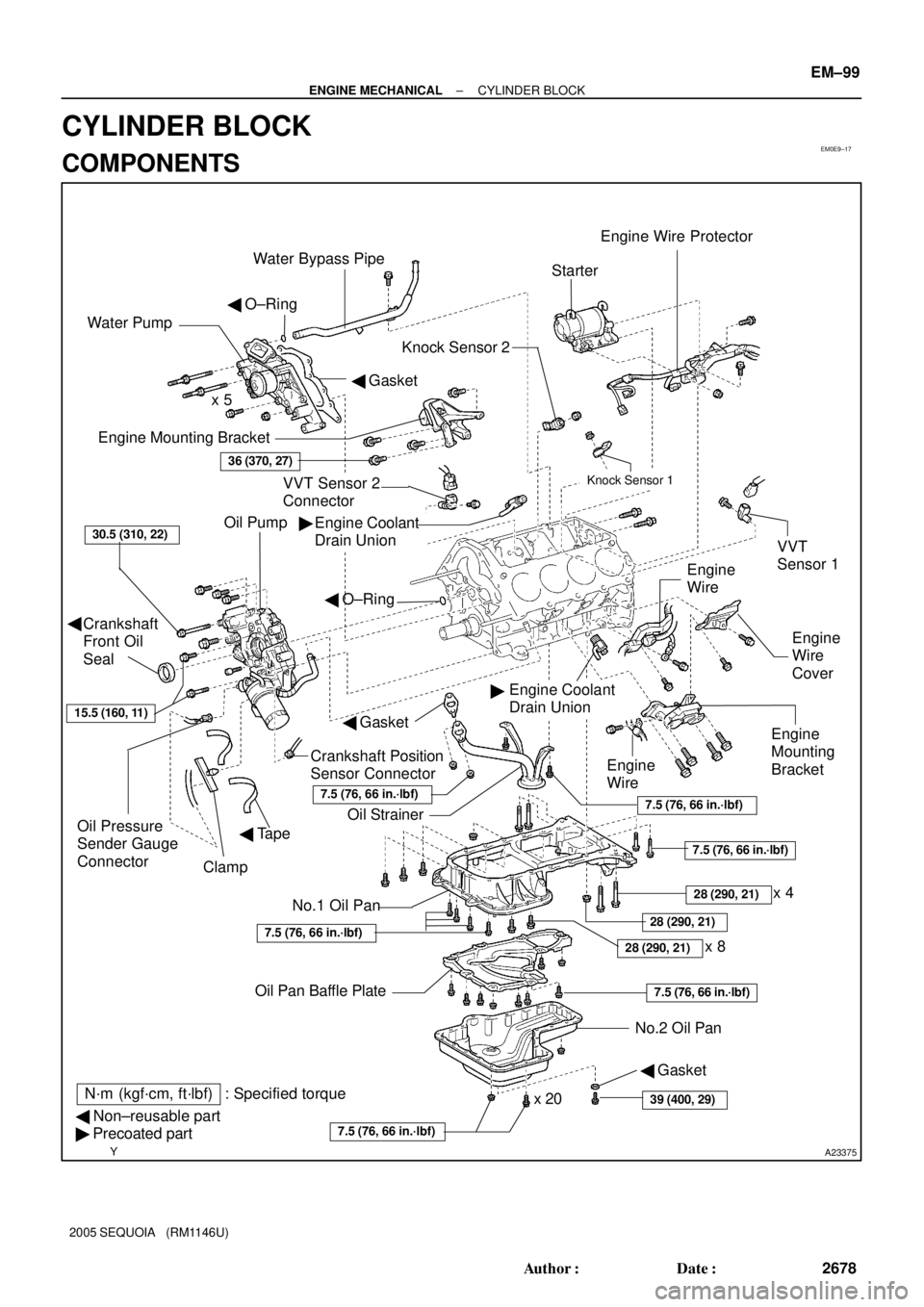
EM0E9±17
A23375
Engine Mounting Bracket
Oil Pump
Crankshaft
Front Oil
Seal
Crankshaft Position
Sensor Connector
No.1 Oil Pan
� Non±reusable part
� Precoated partOil StrainerEngine
Mounting
Bracket
VVT Sensor 2
ConnectorKnock Sensor 1
Knock Sensor 2
Engine Coolant
Drain UnionStarter
No.2 Oil Pan Oil Pan Baffle Platex 8 Water Pump
� Gasket � O±Ring
Engine
Wire
Engine
Wire
Cover VVT
Sensor 1
Engine Coolant
Drain Union
36 (370, 27)
30.5 (310, 22)
x 5
Oil Pressure
Sender Gauge
Connector
7.5 (76, 66 in.´lbf)
7.5 (76, 66 in.´lbf)
7.5 (76, 66 in.´lbf)
N´m (kgf´cm, ft´lbf) : Specified torque �
�
x 20
Clamp
Engine Wire Protector
� Tape
28 (290, 21)
7.5 (76, 66 in.´lbf)
28 (290, 21)
Water Bypass Pipe
7.5 (76, 66 in.´lbf)
� O±Ring
� Gasket
Engine
Wire
15.5 (160, 11)
39 (400, 29)
� Gasket
�
28 (290, 21)
7.5 (76, 66 in.´lbf)
x 4
± ENGINE MECHANICALCYLINDER BLOCK
EM±99
2678 Author�: Date�:
2005 SEQUOIA (RM1146U)
CYLINDER BLOCK
COMPONENTS
Page 2698 of 4323

Front Mark
(2 Cavities)
± ENGINE MECHANICALCYLINDER BLOCK
EM±111
2690 Author�: Date�:
2005")
A04877
A04878
A04879
A23367
Mark 1, 2 or 3 Mark 1, 2 or 3 LH Piston
RH Piston30.75 mmFront Mark
(1 Cavity)
Front Mark
(2 Cavities)
± ENGINE MECHANICALCYLINDER BLOCK
EM±111
2690 Author�: Date�:
2005 SEQUOIA (RM1146U)
3. CLEAN PISTON
(a) Using a gasket scraper, remove the carbon from the pis-
ton top.
(b) Using a groove cleaning tool or broken ring, clean the pis-
ton ring grooves.
(c) Using solvent and a brush, thoroughly clean the piston.
NOTICE:
Do not use a wire brush.
4. INSPECT PISTON AND CONNECTING ROD
(a) Inspect the piston oil clearance.
HINT:
There are 3 sizes of the standard piston diameter, marked º1º,
º2º and º3º accordingly. The mark is stamped on the piston top.
(1) Using a micrometer, measure the piston diameter at
right angles to the piston pin center line, 30.75 mm
(1.2106 in.) from the piston head.
Piston diameter:
STD Mark º1º93.902 to 93.935 mm (3.6969 to 3.6982 in.)STD Mark 1
Mark º2º
93.902 to 93.935 mm (3.6969 to 3.6982 in.)
93.912 to 93.940 mm (3.6973 to 3.6984 in.)Mark 2
Mark º3º
93.912 to 93.940 mm (3.6973 to 3.6984 in.)
93.920 to 93.950 mm (3.6976 to 3.6988 in.)
O/S 0.5094.402 to 94.450 mm (3.7166 to 3.7185 in.)
(2) Measure the cylinder bore diameter in the thrust
directions (see step 2 above).