Page 2706 of 4323
 Front
Mark
(1 Cavity)
Outside Mark LH Piston
RH Piston
Outside Mark
A04860
± ENGINE MECHANICALCYLINDER BLOCK
EM±119
2698 Author�: Date�:")
EM124±07
A04861
A04876
60°C
A23369
Front Mark
(2 Cavities) Front
Mark
(1 Cavity)
Outside Mark LH Piston
RH Piston
Outside Mark
A04860
± ENGINE MECHANICALCYLINDER BLOCK
EM±119
2698 Author�: Date�:
2005 SEQUOIA (RM1146U)
REASSEMBLY
HINT:
�Thoroughly clean all parts to be assembled.
�Before installing the parts, apply new engine oil to all slid-
ing and rotating surfaces.
�Replace all gaskets, O±rings and oil seals with new ones.
1. ASSEMBLE PISTON AND CONNECTING ROD
(a) Using a screwdriver, install a new snap ring on one side
of the piston pin hole.
(b) Gradually heat the piston to about 60°C (140°F).
(c) Coat the piston pin with engine oil.
(d) Position the piston so that the front mark and to the out-
side mark on the connecting rod face in the same direc-
tion as shown in the illustration.
NOTICE:
The installation directions of the piston and connecting rod
are different for the LH and RH banks. The LH piston is
marked with 1 cavity and º2º, the RH piston with 2 cavities
and º2º.
(e) Align the piston pin holes of the piston and connecting
rod, and push in the piston pin with your thumb.
(f) Using a screwdriver, install a new snap ring on the other
side of the piston pin hole.
Page 2711 of 4323

14. INSTALL REAR OIL SEAL RETAINER
(")
A04848
Seal Width
3 ± 4 mm A
BA
B
A04855
New O±Ring
P12477
Seal Packing EM±124
± ENGINE MECHANICALCYLINDER BLOCK
2703 Author�: Date�:
2005 SEQUOIA (RM1146U)
14. INSTALL REAR OIL SEAL RETAINER
(a) Remove any old packing (FIPG) material and be careful
not to drop any oil on the contacting surfaces of the oil
seal retainer and cylinder block.
�Using a razor blade and gasket scraper, remove all
the old packing (FIPG) materials from the gasket
surfaces and sealing grooves.
�Thoroughly clean all components to remove all the
loose material.
�Using a non±residue solvent, clean both sealing
surfaces.
(b) Apply seal packing to the oil seal retainer as shown in the
illustration.
Seal packing: Part No. 08826±00080 or equivalent
�Install a nozzle that has been cut to a 3 ± 4 mm (0.12
± 0.16 in.) opening.
�Parts must be assembled within 5 minutes of ap-
plication. Otherwise the material must be removed
and reapplied.
�Immediately remove nozzle from the tube and rein-
stall cap.
(c) Install a new O±ring to the cylinder block.
(d) Install the oil seal retainer with the 7 bolts.
Torque: 8.0 N´m (80 kgf´cm, 71 in.´lbf)
15. INSTALL ENGINE COOLANT DRAIN UNIONS
(a) Apply seal packing to 2 or 3 threads.
Seal packing: Part No. 08826±00100 or equivalent
Page 2832 of 4323

INSTALLATION
1. INSTALL WATER PUMP
(a) Install a n")
CO0IT±06
B04463
Connect
New O±Ring
B03030
Seal Width
2 ± 3 mm
New O±Ring
CO±8
± COOLINGWATER PUMP
2824 Author�: Date�:
2005 SEQUOIA (RM1146U)
INSTALLATION
1. INSTALL WATER PUMP
(a) Install a new O±ring to the water bypass pipe end.
(b) Apply soapy water to the O±ring.
(c) Connect the water pump to the water bypass pipe end.
(d) Install the water pump and a new gasket with the 5 bolts,
2 stud bolts and nut. Uniformly tighten the bolts, stud bolts
and nut in several passes.
Torque:
Bolt: 21 N´m (215 kgf´cm, 15 ft´lbf)
Stud bolt and nut: 18 N´m (185 kgf´cm, 13 ft´lbf)
2. INSTALL WATER INLET AND INLET HOUSING AS-
SEMBLY
(a) Remove any old packing (FIPG) material and be careful
not to drop any oil on the contact surfaces of the water in-
let housing and water pump.
�Using a razor blade and gasket scraper, remove all
the old packing (FIPG) material from the gasket sur-
faces and sealing groove.
�Thoroughly clean all components to remove all the
loose material.
�Using a non±residue solvent, clean both sealing
surfaces.
(b) Apply seal packing to the sealing groove of water inlet
housing as shown in the illustration.
Seal packing: Part No. 08826±00100 or equivalent
�Install a nozzle that has been cut to a 2 ± 3 mm (0.08
± 0.12 in.) opening.
�Parts must be assembled within 3 minutes of ap-
plication. Otherwise the material must be removed
and reapplied.
�Immediately remove nozzle from the tube and rein-
stall cap.
(c) Install a new O±ring to the water inlet housing.
(d) Apply soapy water on the O±ring.
(e) Attach the water inlet housing end to the front water by-
pass joint hole.
Page 2844 of 4323

REPLACEMENT
CAUTION:
�Prolonged and repeated contact with mineral oil will
result in the r")
LU0GW±07
B07231
B07232
SST
LU±2
± LUBRICATIONOIL AND FILTER
2836 Author�: Date�:
2005 SEQUOIA (RM1146U)
REPLACEMENT
CAUTION:
�Prolonged and repeated contact with mineral oil will
result in the removal of natural fats from the skin,
leading to dryness, irritation and dermatitis. In addi-
tion, used engine oil contains potentially harmful
contaminants which may cause skin cancer.
�Care should be taken, therefore, when changing en-
gine oil to minimize the frequency and length of time
your skin is exposed to used engine oil. Protective
clothing and gloves that cannot be penetrated by oil
should be worn. The skin should be thoroughly
washed with soap and water, or use water±less hand
cleaner, to remove any used engine oil. Do not use
gasoline, thinners, or solvents.
�In order to preserve the environment, used oil and
used oil filters must be disposed of only at desig-
nated disposal sites.
1. w/ Oil filter change:
REMOVE ENGINE UNDER COVER
2. DRAIN ENGINE OIL
(a) Remove the oil filler cap.
(b) Remove the oil drain plug and gasket, and drain the oil
into a container.
3. REPLACE OIL FILTER
(a) Using SST, remove the oil filter.
SST 09228±07501
(b) Clean the oil filter contact surface on the oil filter mount-
ing.
(c) Lubricate the filter rubber gasket with clean engine oil.
Page 2845 of 4323
B07233
B07234
SST
3/4 Turn
B07235
Front
± LUBRICATIONOIL AND FILTER
LU±3
2837 Author�: Date�:
2005 SEQUOIA (RM1146U)
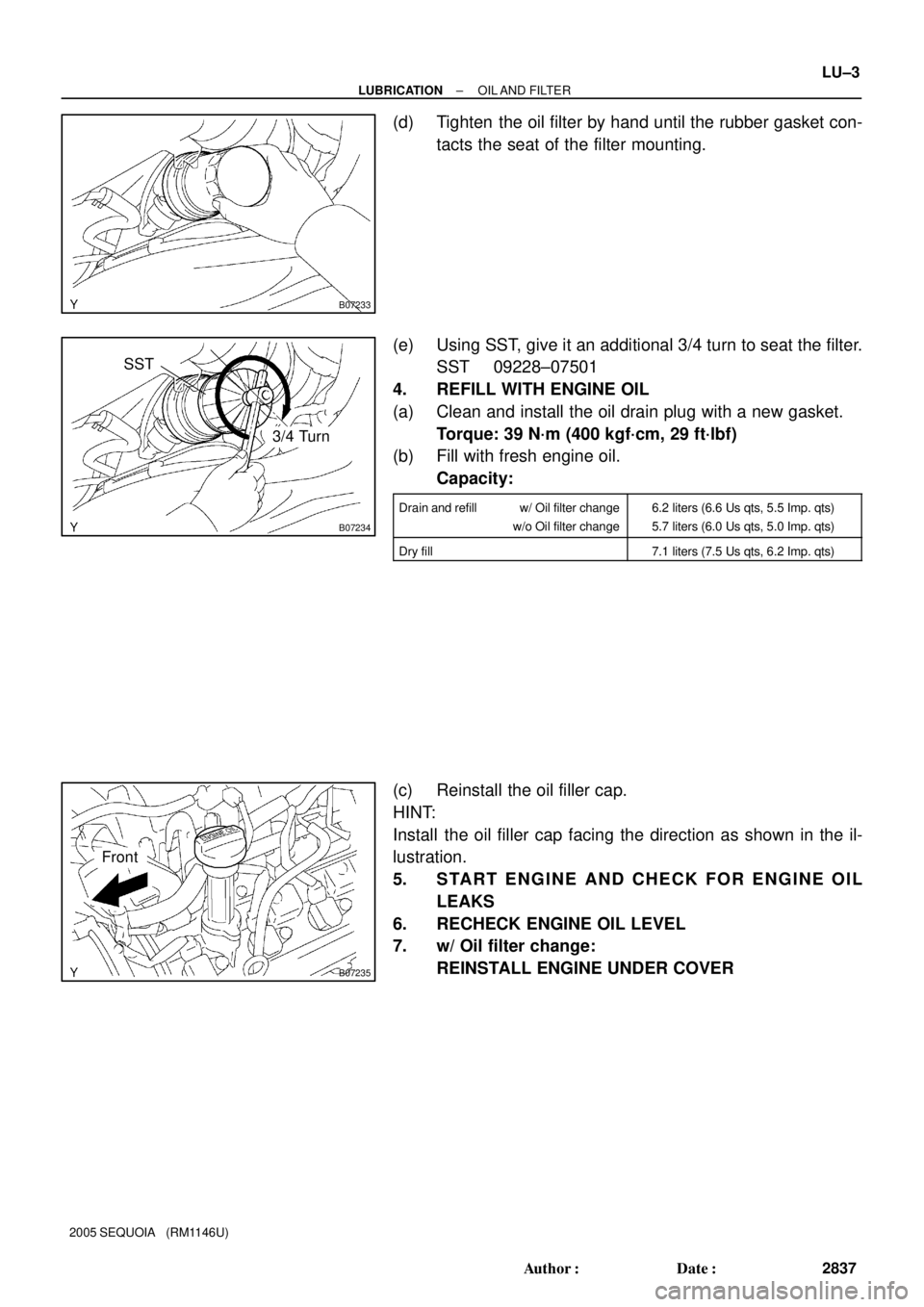
(d) Tighten the oil filter by hand until the rubber gasket con-
tacts the seat of the filter mounting.
(e) Using SST, give it an additional 3/4 turn to seat the filter.
SST 09228±07501
4. REFILL WITH ENGINE OIL
(a) Clean and install the oil drain plug with a new gasket.
Torque: 39 N´m (400 kgf´cm, 29 ft´lbf)
(b) Fill with fresh engine oil.
Capacity:
Drain and refill w/ Oil filter change
w/o Oil filter change6.2 liters (6.6 Us qts, 5.5 Imp. qts)
5.7 liters (6.0 Us qts, 5.0 Imp. qts)
Dry fill7.1 liters (7.5 Us qts, 6.2 Imp. qts)
(c) Reinstall the oil filler cap.
HINT:
Install the oil filler cap facing the direction as shown in the il-
lustration.
5. START ENGINE AND CHECK FOR ENGINE OIL
LEAKS
6. RECHECK ENGINE OIL LEVEL
7. w/ Oil filter change:
REINSTALL ENGINE UNDER COVER
Page 2847 of 4323
B17481
GeneratorDrive Belt Tensioner
No.1 Timing Belt Cover
Crankshaft Pulley
Timing Belt
Timing Belt Guide
(Crankshaft Angle Sensor Plate)No.1 Idler Pulley
Crankshaft Timing PulleyPlate Washer
No.2 Idler Pulley
Timing Belt Cover SpacerGasket
� Precoated part
N´m (kgf´cm, ft´lbf) : Specified torque
39 (400, 29)
Generator Wire
�34.5 (350, 25)
34.5 (350, 25)
39 (400, 29)
15.5 (158, 11)
± LUBRICATIONOIL PUMP
LU±5
2839 Author�: Date�:
2005 SEQUOIA (RM1146U)
Page 2848 of 4323
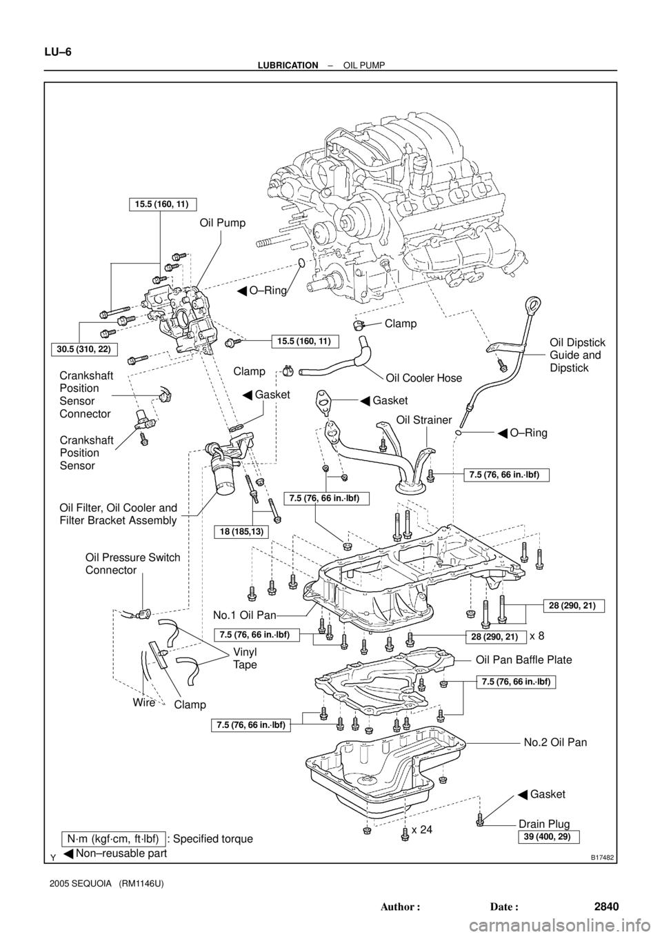
B17482
Oil Pump
Crankshaft
Position
Sensor
Connector
Crankshaft
Position
Sensor
Oil Filter, Oil Cooler and
Filter Bracket AssemblyOil Cooler Hose Clamp
Oil StrainerOil Dipstick
Guide and
Dipstick � O±Ring
� Gasket
No.1 Oil Pan
No.2 Oil Pan Oil Pan Baffle Plate Clamp
Drain Plug
x 24
N´m (kgf´cm, ft´lbf) : Specified torque
� Non±reusable part
� Gasket
30.5 (310, 22)
� O±Ring
15.5 (160, 11)
18 (185,13)
Vinyl
Tape
Wire
Clamp
Oil Pressure Switch
Connector
15.5 (160, 11)
� Gasket
39 (400, 29)
x 828 (290, 21)
7.5 (76, 66 in.´lbf)
28 (290, 21)
7.5 (76, 66 in.´lbf)
7.5 (76, 66 in.´lbf)
7.5 (76, 66 in.´lbf)
7.5 (76, 66 in.´lbf)
LU±6
± LUBRICATIONOIL PUMP
2840 Author�: Date�:
2005 SEQUOIA (RM1146U)
Page 2850 of 4323

REMOVAL
HINT:
When repairing the oil pump, the oil pan and strainer should be
removed an")
LU08Q±10
B05837
Pull O±Ring
B05838
LU±8
± LUBRICATIONOIL PUMP
2842 Author�: Date�:
2005 SEQUOIA (RM1146U)
REMOVAL
HINT:
When repairing the oil pump, the oil pan and strainer should be
removed and cleaned.
1. REMOVE ENGINE FROM VEHICLE
(2WD: See page EM±79)
(4WD: See page EM±92)
2. INSTALL ENGINE TO ENGINE STAND FOR DIS-
ASSEMBLY
3. REMOVE TIMING BELT (See page EM±16)
4. REMOVE NO.1 IDLER PULLEY (See page EM±16)
5. REMOVE NO.2 IDLER PULLEY (See page EM±16)
6. REMOVE CRANKSHAFT TIMING PULLEY
(See page EM±16)
7. REMOVE CRANKSHAFT POSITION SENSOR
(See page IG±11)
8. REMOVE OIL DIPSTICK AND GUIDE
(a) Remove the bolt holding the oil dipstick to the LH cylinder
head.
(b) Pull out the dipstick guide together with the dipstick from
the No.1 oil pan.
(c) Remove the O±ring from the dipstick guide.
9. REMOVE OIL FILTER, OIL COOLER AND FILTER
BRACKET ASSEMBLY
(a) Disconnect the oil pressure switch connector.
(b) Take out the vinyl tape, and disconnect the wire from the
clamp.
(c) Turn the clamp counterclockwise, and remove the clamp
from the oil filter bracket.
(d) Disconnect the oil cooler hose from the oil cooler.
(e) Remove the 2 bolts, nut, the oil filter, oil cooler and filter
bracket assembly.
(f) Remove the gasket from the filter bracket.
No.1 Idler Pulley
Crankshaft Timing PulleyPlate Washer
No.2 I")