Page 3259 of 4323

F13260
F17896
BMatchmarks
A
F19948
Mark
SR±24
± STEERINGTILT STEERING COLUMN
3251 Author�: Date�:
2005 SEQUOIA (RM1146U)
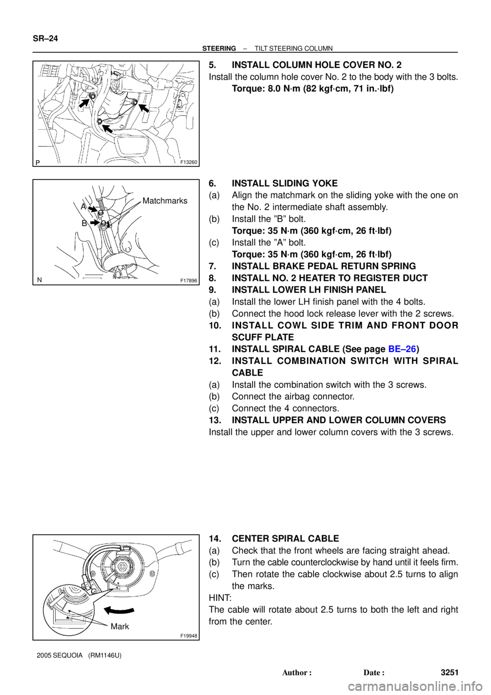
5. INSTALL COLUMN HOLE COVER NO. 2
Install the column hole cover No. 2 to the body with the 3 bolts.
Torque: 8.0 N´m (82 kgf´cm, 71 in.´lbf)
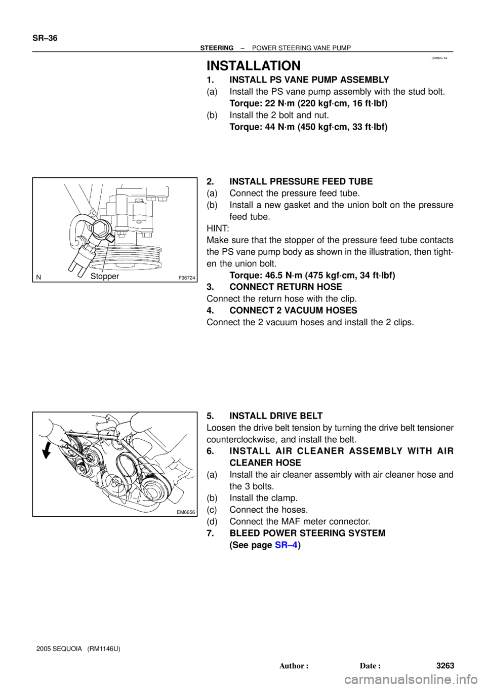
6. INSTALL SLIDING YOKE
(a) Align the matchmark on the sliding yoke with the one on
the No. 2 intermediate shaft assembly.
(b) Install the ºBº bolt.
Torque: 35 N´m (360 kgf´cm, 26 ft´lbf)
(c) Install the ºAº bolt.
Torque: 35 N´m (360 kgf´cm, 26 ft´lbf)
7. INSTALL BRAKE PEDAL RETURN SPRING
8. INSTALL NO. 2 HEATER TO REGISTER DUCT
9. INSTALL LOWER LH FINISH PANEL
(a) Install the lower LH finish panel with the 4 bolts.
(b) Connect the hood lock release lever with the 2 screws.
10. INSTALL COWL SIDE TRIM AND FRONT DOOR
SCUFF PLATE
11. INSTALL SPIRAL CABLE (See page BE±26)
12. INSTALL COMBINATION SWITCH WITH SPIRAL
CABLE
(a) Install the combination switch with the 3 screws.
(b) Connect the airbag connector.
(c) Connect the 4 connectors.
13. INSTALL UPPER AND LOWER COLUMN COVERS
Install the upper and lower column covers with the 3 screws.
14. CENTER SPIRAL CABLE
(a) Check that the front wheels are facing straight ahead.
(b) Turn the cable counterclockwise by hand until it feels firm.
(c) Then rotate the cable clockwise about 2.5 turns to align
the marks.
HINT:
The cable will rotate about 2.5 turns to both the left and right
from the center.
Page 3263 of 4323
SR0ME±08
EM6656
SR±28
± STEERINGPOWER STEERING VANE PUMP
3255 Author�: Date�:
2005 SEQUOIA (RM1146U)
REMOVAL
1. REMOVE AIR CLEANER ASSEMBLY WITH AIR
CLEANER HOSE
(a) Disconnect the MAF meter connector.
(b) Disconnect the hoses.
(c) Remove the clamp.
(d) Remove the 3 bolts and air cleaner assembly with air
cleaner hose connected.
2. REMOVE DRIVE BELT
Loosen the drive belt tension by turning the drive belt tensioner
counterclockwise, and remove the drive belt.
3. DISCONNECT 2 VACUUM HOSES
Remove the 2 clips and disconnect the 2 vacuum hoses.
4. DISCONNECT RETURN HOSE
Remove the clip and disconnect the return hose.
5. DISCONNECT PRESSURE FEED TUBE
Remove the union bolt and gasket, disconnect the pressure
feed tube.
6. REMOVE PS VANE PUMP ASSEMBLY
Remove the 2 bolts, nut, stud bolt and PS vane pump assembly.
Page 3271 of 4323

SR0MI±14
F06724Stopper
EM6656
SR±36
± STEERINGPOWER STEERING VANE PUMP
3263 Author�: Date�:
2005 SEQUOIA (RM1146U)
INSTALLATION
1. INSTALL PS VANE PUMP ASSEMBLY
(a) Install the PS vane pump assembly with the stud bolt.
Torque: 22 N´m (220 kgf´cm, 16 ft´lbf)
(b) Install the 2 bolt and nut.
Torque: 44 N´m (450 kgf´cm, 33 ft´lbf)
2. INSTALL PRESSURE FEED TUBE
(a) Connect the pressure feed tube.
(b) Install a new gasket and the union bolt on the pressure
feed tube.
HINT:
Make sure that the stopper of the pressure feed tube contacts
the PS vane pump body as shown in the illustration, then tight-
en the union bolt.
Torque: 46.5 N´m (475 kgf´cm, 34 ft´lbf)
3. CONNECT RETURN HOSE
Connect the return hose with the clip.
4. CONNECT 2 VACUUM HOSES
Connect the 2 vacuum hoses and install the 2 clips.
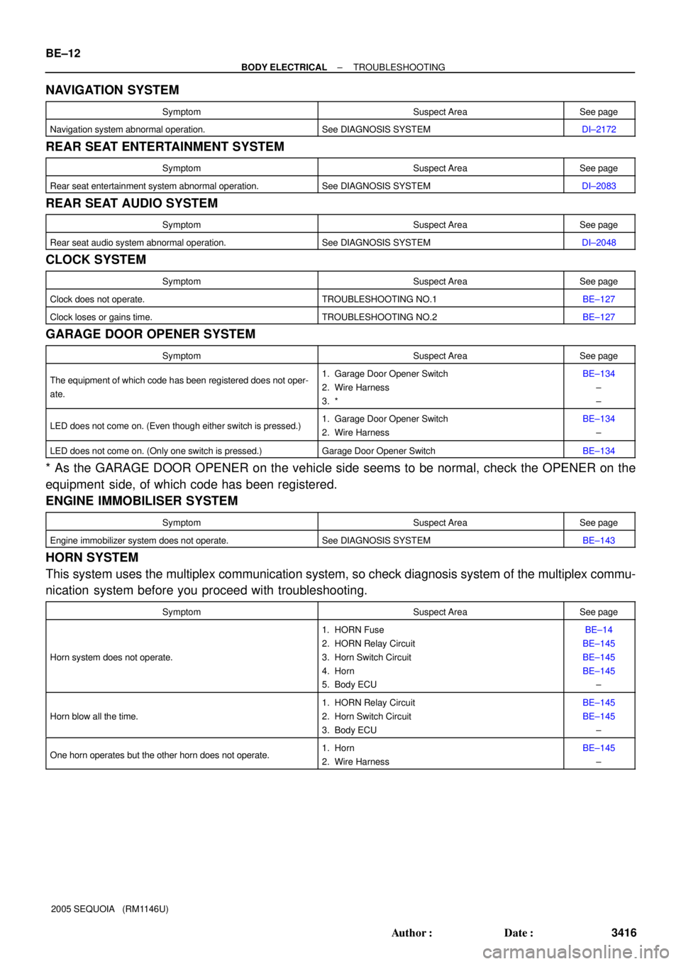
5. INSTALL DRIVE BELT
Loosen the drive belt tension by turning the drive belt tensioner
counterclockwise, and install the belt.
6. INSTALL AIR CLEANER ASSEMBLY WITH AIR
CLEANER HOSE
(a) Install the air cleaner assembly with air cleaner hose and
the 3 bolts.
(b) Install the clamp.
(c) Connect the hoses.
(d) Connect the MAF meter connector.
7. BLEED POWER STEERING SYSTEM
(See page SR±4)
Page 3279 of 4323
R11651
SSTWire Cylinder End
Stopper
F08343
SST
F08340Oil Seal SST
SR±44
± STEERINGPOWER STEERING GEAR
3271 Author�: Date�:
2005 SEQUOIA (RM1146U)
14. REMOVE CYLINDER END STOPPER
(a) Using SST, turn the stopper clockwise until the wire end
can be seen through the service hole.
SST 09631±16010
(b) Using SST, turn the stopper counterclockwise, and re-
move the wire.
SST 09631±16010
15. REMOVE STEERING RACK AND BUSHING
(a) Using SST, press out the steering rack with the bushing.
NOTICE:
Take care not to drop the rack.
SST 09950±70010 (09951±07200)
(b) Remove the bushing from the rack.
(c) Remove the O±ring from the bushing.
16. REMOVE OIL SEAL
Using SST, press out the oil seal.
SST 09950±60010 (09951±00360),
09950±70010 (09951±07360)
Page 3285 of 4323

R11656
SST
Wire
Cylinder End
Stopper
F06757
SST
F06758
Vinyl Tape
F08339Oil Seal SST
SR±50
± STEERINGPOWER STEERING GEAR
3277 Author�: Date�:
2005 SEQUOIA (RM1146U)
5. INSTALL CYLINDER END STOPPER
(a) Align the installation hole for the wire of the stopper with
the slot of the rack housing.
(b) Install a new wire into the stopper.
(c) Using SST, turn the stopper clockwise 400° to 500°.
SST 09631±16010
6. AIR TIGHTNESS TEST
(a) Install SST to the rack housing.
SST 09631±12071
(b) Apply 53 kPa (400 mmHg, 15.75 in.Hg) of vacuum for
about 30 seconds.
(c) Check that there is no change in the vacuum.
If there is change in the vacuum, check the installation of the oil
seals.
7. INSTALL CONTROL VALVE ASSEMBLY
(a) To prevent oil seal lip damage, wind vinyl tape on the ser-
rated part of the valve shaft.
(b) Coat the teflon rings with power steering fluid.
(c) Install the valve assembly into the valve housing.
NOTICE:
Be careful not to damage the teflon rings and oil seal.
8. INSTALL OIL SEAL
(a) Coat a new oil seal lip with power steering fluid.
(b) Using SST, press in the oil seal.
SST 09612±22011
NOTICE:
Make sure to install the oil seal in the correct direction.
9. INSTALL CONTROL VALVE HOUSING WITH CON-
TROL VALVE ASSEMBLY
(a) Place a new gasket on the rack housing.
(b) Align the matchmarks on the control valve housing with
the one on the rack housing.
(c) Install the 2 bolts.
Torque: 18 N´m (185 kgf´cm, 13 ft´lbf)
Page 3424 of 4323

BE±12
± BODY ELECTRICALTROUBLESHOOTING
3416 Author�: Date�:
2005 SEQUOIA (RM1146U)
NAVIGATION SYSTEM
SymptomSuspect AreaSee page
Navigation system abnormal operation.See DIAGNOSIS SYSTEMDI±2172
REAR SEAT ENTERTAINMENT SYSTEM
SymptomSuspect AreaSee page
Rear seat entertainment system abnormal operation.See DIAGNOSIS SYSTEMDI±2083
REAR SEAT AUDIO SYSTEM
SymptomSuspect AreaSee page
Rear seat audio system abnormal operation.See DIAGNOSIS SYSTEMDI±2048
CLOCK SYSTEM
SymptomSuspect AreaSee page
Clock does not operate.TROUBLESHOOTING NO.1BE±127
Clock loses or gains time.TROUBLESHOOTING NO.2BE±127
GARAGE DOOR OPENER SYSTEM
SymptomSuspect AreaSee page
The equipment of which code has been registered does not oper-
ate.1. Garage Door Opener Switch
2. Wire Harness
3. *BE±134
±
±
LED does not come on. (Even though either switch is pressed.)1. Garage Door Opener Switch
2. Wire HarnessBE±134
±
LED does not come on. (Only one switch is pressed.)Garage Door Opener SwitchBE±134
* As the GARAGE DOOR OPENER on the vehicle side seems to be normal, check the OPENER on the
equipment side, of which code has been registered.
ENGINE IMMOBILISER SYSTEM
SymptomSuspect AreaSee page
Engine immobilizer system does not operate.See DIAGNOSIS SYSTEMBE±143
HORN SYSTEM
This system uses the multiplex communication system, so check diagnosis system of the multiplex commu-
nication system before you proceed with troubleshooting.
SymptomSuspect AreaSee page
Horn system does not operate.
1. HORN Fuse
2. HORN Relay Circuit
3. Horn Switch Circuit
4. Horn
5. Body ECUBE±14
BE±145
BE±145
BE±145
±
Horn blow all the time.
1. HORN Relay Circuit
2. Horn Switch Circuit
3. Body ECUBE±145
BE±145
±
One horn operates but the other horn does not operate.1. Horn
2. Wire HarnessBE±145
±
Page 3481 of 4323

BE2MO±01
I08152
N14863
3 12
53
15
2
I1535121
I1535221
± BODY ELECTRICALPOWER WINDOW CONTROL SYSTEM
BE±69
3473 Author�: Date�:
2005 SEQUOIA (RM1146U)
INSPECTION
1. INSPECT REAR DOOR POWER WINDOW SWITCH
CONTINUITY
Switch positionTester connectionSpecified condition
UP2 ± 3, 4 ± 5Continuity
OFF2 ± 3 ± 5Continuity
DOWN2 ± 4, 3 ± 5Continuity
If continuity is not as specified, replace the switch.
2. INSPECT POWER WINDOW SWITCH CIRCUIT
(Driver 's Door: See page DI±1788)
(Passenger 's Door: See page DI±1826)
(Rear Door: See page DI±1747)
(Back Door: See page DI±1747)
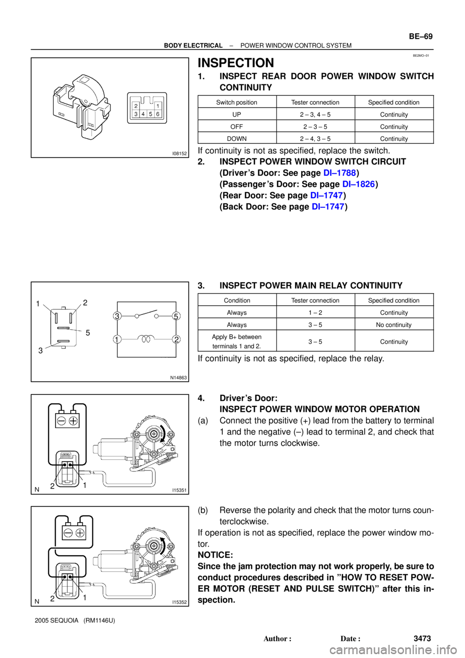
3. INSPECT POWER MAIN RELAY CONTINUITY
ConditionTester connectionSpecified condition
Always1 ± 2Continuity
Always3 ± 5No continuity
Apply B+ between
terminals 1 and 2.3 ± 5Continuity
If continuity is not as specified, replace the relay.
4. Driver 's Door:
INSPECT POWER WINDOW MOTOR OPERATION
(a) Connect the positive (+) lead from the battery to terminal
1 and the negative (±) lead to terminal 2, and check that
the motor turns clockwise.
(b) Reverse the polarity and check that the motor turns coun-
terclockwise.
If operation is not as specified, replace the power window mo-
tor.
NOTICE:
Since the jam protection may not work properly, be sure to
conduct procedures described in ºHOW TO RESET POW-
ER MOTOR (RESET AND PULSE SWITCH)º after this in-
spection.
Page 3482 of 4323

I05476
2
1
I054772
1
I153572
1
I153582
1
I15353
2
1
BE±70
± BODY ELECTRICALPOWER WINDOW CONTROL SYSTEM
3474 Author�: Date�:
2005 SEQUOIA (RM1146U)
5. Passenger 's Door:
INSPECT POWER WINDOW MOTOR OPERATION
(a) Connect the positive (+) lead from the battery to terminal
1 and the negative (±) lead to terminal 2, and check that
the motor turns clockwise.
(b) Reverse the polarity and check that the motor turns coun-
terclockwise.
If operation is not as specified, replace the power window mo-
tor.
NOTICE:
Since the jam protection may not work properly, be sure to
conduct procedures described in ºHOW TO RESET POW-
ER MOTOR (RESET AND PULSE SWITCH)º after this in-
spection.
6. Rear Right Door:
INSPECT POWER WINDOW MOTOR OPERATION
(a) Connect the positive (+) lead from the battery to terminal
1 and the negative (±) lead to terminals 2, and check that
the motor turns clockwise.
(b) Reverse the polarity and check that the motor turns coun-
terclockwise.
If operation is not as specified, replace the power window mo-
tor.
7. Rear Left Door:
INSPECT POWER WINDOW MOTOR OPERATION
(a) Connect the positive (+) lead from the battery to terminal
1 and the negative (±) lead to terminal 2, and check that
the motor turns clockwise.