Page 1887 of 4323

± DIAGNOSTICSBODY CONTROL SYSTEM
DI±1685
1879 Author�: Date�:
2005 SEQUOIA (RM1146U)
ILLUMINATED ENTRY:
DISPLAY (ITEM)DEFAULTCONTENTSSETTING
I/L ON/UNLOCKONIlluminates interior light when ignition switch is turned from
ACC to LOCK position.ON/OFF
LIGHTING TIME15SChanges lighting time after closing doors (light quickly fades
out when ignition switch is turned on).15S/7.5S/30S
LIGHT CONTROL:
DISPLAY (ITEM)DEFAULTCONTENTSSETTING
SENSITIVITYNORMALSensitivity adjustment is difficult to confirm. Check by driving
the customer's vehicle.NORMAL/DARK2/DARK1/
LIGHT1/LIGHT2
LIGHT OFF DELAY30S
Keeps headlights on for a certain period of time after closing
all doors with ignition switch on, light control switch in HEAD
or AUTO position, and headlights on.
OFF/30S/60S/90S
DISP EX ON SENNORMALChanges brightness of lights such as combination meter
indicator light, A/C indicator lamp, and clock lamp.NORMAL/DARK2/DARK1/
LIGHT1/LIGHT2
DISP OFF SENNORMALChanges brightness of lights such as combination meter
indicator light, A/C indicator lamp, and clock lamp.NORMAL/DARK2/DARK1/
LIGHT1/LIGHT2
Page 2209 of 4323
I28576
270°
Bright
0°
DarkR6
ILL±
I28577
Light Control Rheostat
Wire Harness View:
R6
E
± DIAGNOSTICSAUDIO SYSTEM
DI±2007
2201 Author�: Date�:
2005 SEQUOIA (RM1146U)
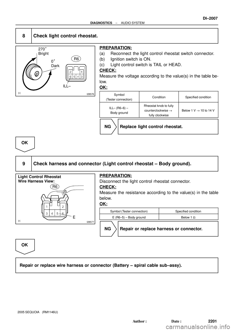
8 Check light control rheostat.
PREPARATION:
(a) Reconnect the light control rheostat switch connector.
(b) Ignition switch is ON.
(c) Light control switch is TAIL or HEAD.
CHECK:
Measure the voltage according to the value(s) in the table be-
low.
OK:
Symbol
(Tester connection)ConditionSpecified condition
ILL± (R6±6) ±
Body groundRheostat knob to fully
counterclockwise "
fully clockwise
Below 1 V " 10 to 14 V
NG Replace light control rheostat.
OK
9 Check harness and connector (Light control rheostat ± Body ground).
PREPARATION:
Disconnect the light control rheostat connector.
CHECK:
Measure the resistance according to the value(s) in the table
below.
OK:
Symbol (Tester connection)Specified condition
E (R6±5) ± Body groundBelow 1 W
NG Repair or replace harness or connector.
OK
Repair or replace wire harness or connector (Battery ± spiral cable sub±assy).
Page 2394 of 4323

I28236*1
*2*3
*4 *1
*2
DI±2192
± DIAGNOSTICSNAVIGATION SYSTEM
2386 Author�: Date�:
2005 SEQUOIA (RM1146U)
5. DIAGNOSIS DISPLAY DETAILED DESCRIPTION
HINT:
�This section contains a detailed description of displays within diagnostic mode.
�Illustrations may differ from the actual vehicle depending on the device settings and options. There-
fore, some detailed areas may not be shown exactly the same as on the actual vehicle.
(a) System Checks
(1) System Check Mode Screen
Device Names and Hardware Address/*1
HINT:
�Registered device names are displayed.
�If a device name is unknown to the system, its physical address is shown instead.
Address No.NameAddress No.Name
11 0EMV120AV X
1281DIN TV140AV N
144G±BOOK178NAVI
17CMONET190AUDIO H/U
1ACCAMERA±C1B0Rr±TV
1C0Rr±CONT1C2TV±TUNER2
1C4PANEL1C6G/W
1C8FM±M±LCD1D8CONT±SW
1ECBODY1F0RADIO TUNER
1F1XM1F2SIRIUS
230TV±TUNER240CD±CH2
250DVD±CH280CAMERA
360CD±CH13A0MD±CH
17DTEL440DSP±AMP
530ETC5C8MAYDAY
1A0DVD±P1D6CLOCK
1F4RSA1F6RSE
480AMP±±
Page 2468 of 4323
I28750
Radio and Navigation Assy
Wire Harness View:
R27
SWG
I28294
Spiral Cable Sub±assy
Connector Front View:
C9
I28576
270°
Bright
0°
DarkR6
ILL±
DI±2266
± DIAGNOSTICSNAVIGATION SYSTEM
2460 Author�: Date�:
2005 SEQUOIA (RM1146U)
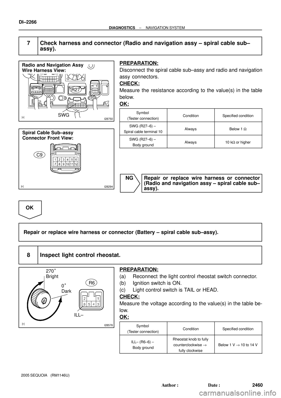
7 Check harness and connector (Radio and navigation assy ± spiral cable sub±
assy).
PREPARATION:
Disconnect the spiral cable sub±assy and radio and navigation
assy connectors.
CHECK:
Measure the resistance according to the value(s) in the table
below.
OK:
Symbol
(Tester connection)ConditionSpecified condition
SWG (R27±6) ±
Spiral cable terminal 10AlwaysBelow 1 W
SWG (R27±6) ±
Body groundAlways10 kW or higher
NG Repair or replace wire harness or connector
(Radio and navigation assy ± spiral cable sub±
assy).
OK
Repair or replace wire harness or connector (Battery ± spiral cable sub±assy).
8 Inspect light control rheostat.
PREPARATION:
(a) Reconnect the light control rheostat switch connector.
(b) Ignition switch is ON.
(c) Light control switch is TAIL or HEAD.
CHECK:
Measure the voltage according to the value(s) in the table be-
low.
OK:
Symbol
(Tester connection)ConditionSpecified condition
ILL± (R6±6) ±
Body groundRheostat knob to fully
counterclockwise "
fully clockwise
Below 1 V " 10 to 14 V
Page 2570 of 4323
I28843
Integration Control
and Panel
ACC D
15 A CIG I18
Ignition Switch
120 1
40 A AM1
F10
Fusible Link
Block
Battery 2 Instrument Panel J/B3
P
W
B 11L1C
6P
1E AM1
140 A ALT
ACC
5 W±L
1C
8 W±L111
I19 J15
J/C
P Instrument Panel J/B
D
GND 10
I19 O O
J43 J43J/C
A
A
IG
Cowl Side Panel RH
DI±2368
± DIAGNOSTICSAIR CONDITIONING SYSTEM
2562 Author�: Date�:
2005 SEQUOIA (RM1146U)
ACC Power Source Circuit
CIRCUIT DESCRIPTION
This circuit supplies power to the integration control and panel. It supplies power to the illumination for the
clock.
WIRING DIAGRAM
DI938±04
Page 2605 of 4323
A23307Turn
A23308
A14391
Approx. 50°Idler
Pulley
Bolt
Timing
Mark
Crankshaft
Pulley Bolt
Turn
A23309
EM±18
± ENGINE MECHANICALTIMING BELT
2597 Author�: Date�:
2005 SEQUOIA (RM1146U)
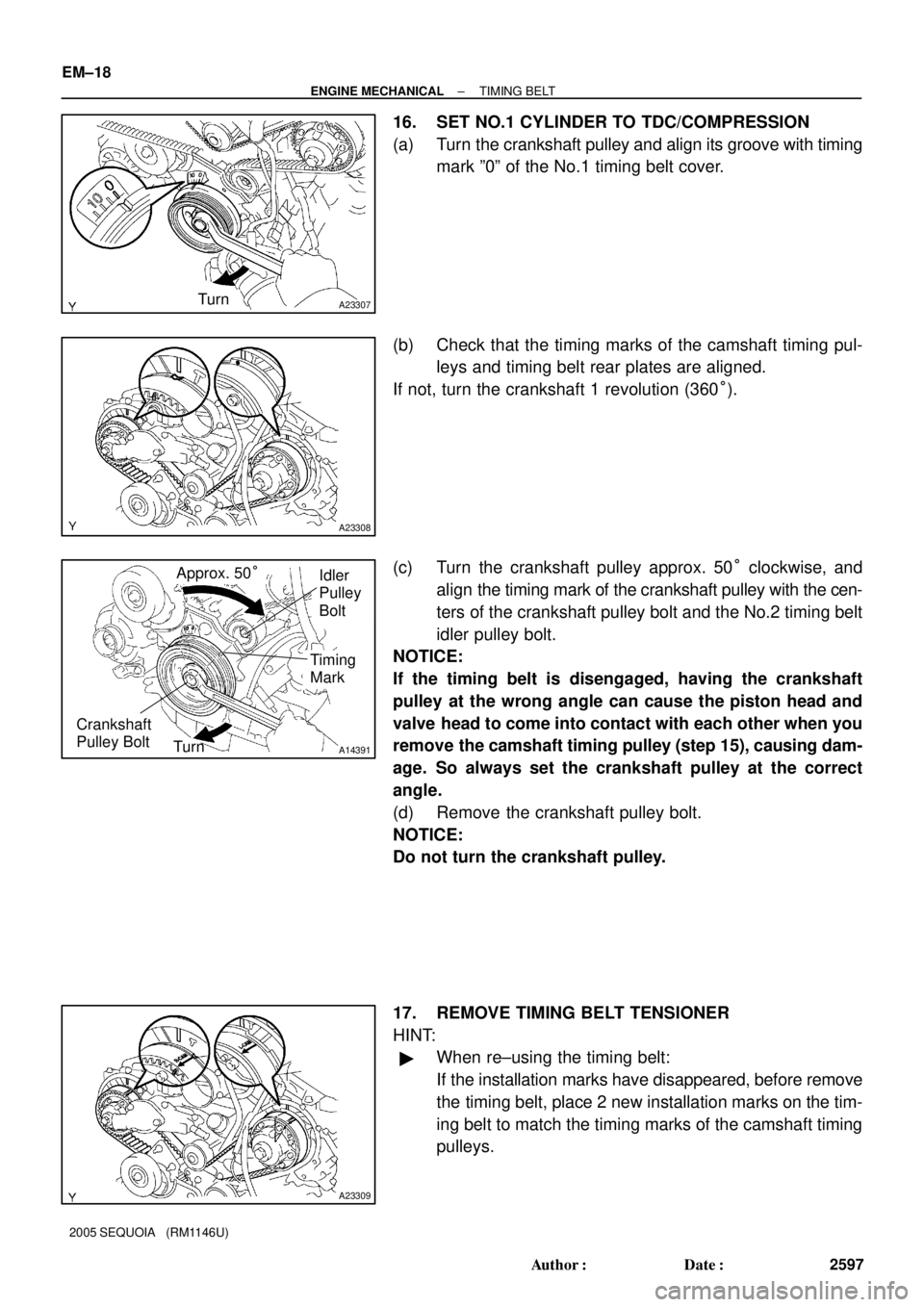
16. SET NO.1 CYLINDER TO TDC/COMPRESSION
(a) Turn the crankshaft pulley and align its groove with timing
mark º0º of the No.1 timing belt cover.
(b) Check that the timing marks of the camshaft timing pul-
leys and timing belt rear plates are aligned.
If not, turn the crankshaft 1 revolution (360°).
(c) Turn the crankshaft pulley approx. 50° clockwise, and
align the timing mark of the crankshaft pulley with the cen-
ters of the crankshaft pulley bolt and the No.2 timing belt
idler pulley bolt.
NOTICE:
If the timing belt is disengaged, having the crankshaft
pulley at the wrong angle can cause the piston head and
valve head to come into contact with each other when you
remove the camshaft timing pulley (step 15), causing dam-
age. So always set the crankshaft pulley at the correct
angle.
(d) Remove the crankshaft pulley bolt.
NOTICE:
Do not turn the crankshaft pulley.
17. REMOVE TIMING BELT TENSIONER
HINT:
�When re±using the timing belt:
If the installation marks have disappeared, before remove
the timing belt, place 2 new installation marks on the tim-
ing belt to match the timing marks of the camshaft timing
pulleys.
Page 2606 of 4323
A23310
String
A04339
A23311
Slightly Turn
A23312
SST
± ENGINE MECHANICALTIMING BELT
EM±19
2598 Author�: Date�:
2005 SEQUOIA (RM1146U)
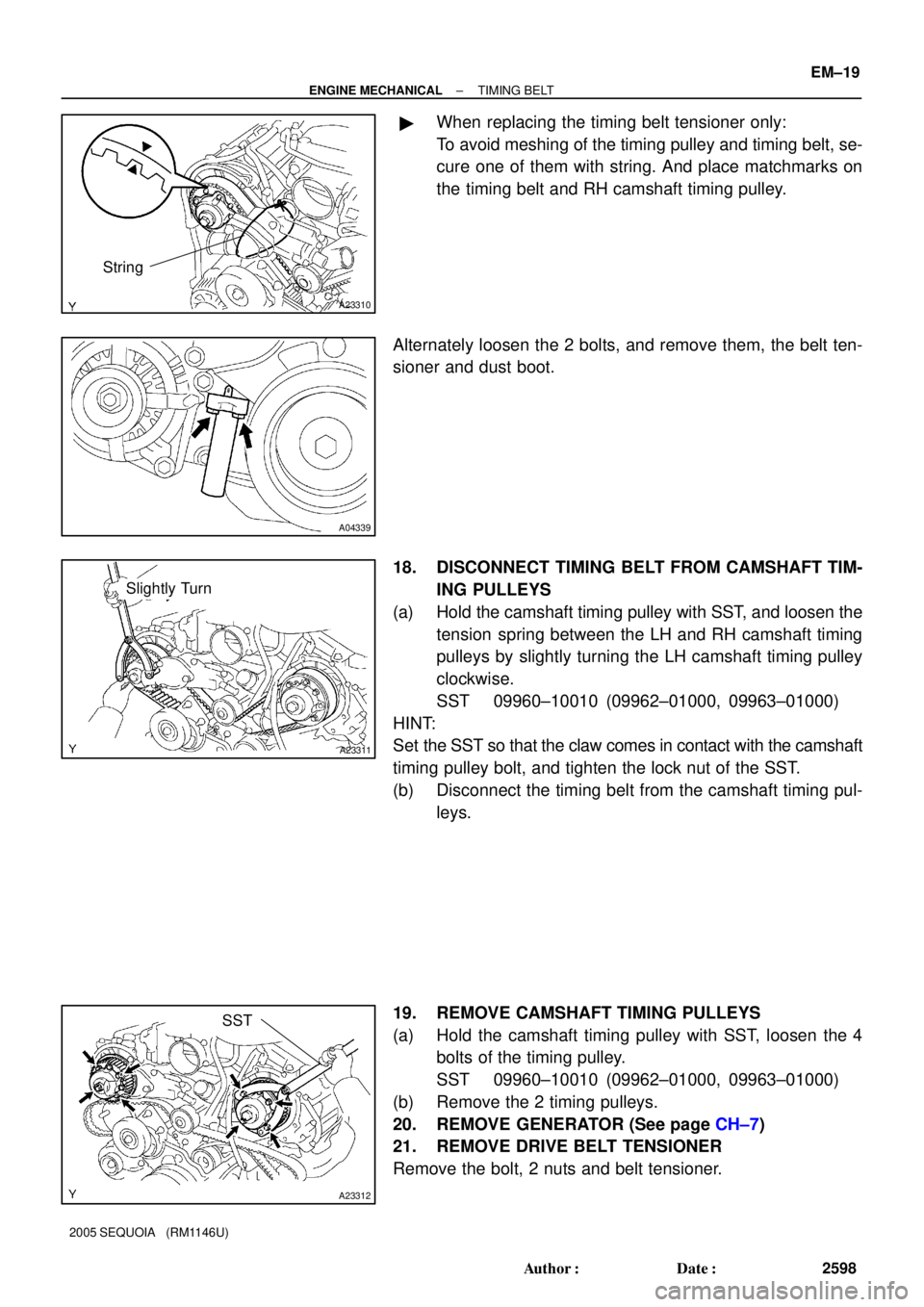
�When replacing the timing belt tensioner only:
To avoid meshing of the timing pulley and timing belt, se-
cure one of them with string. And place matchmarks on
the timing belt and RH camshaft timing pulley.
Alternately loosen the 2 bolts, and remove them, the belt ten-
sioner and dust boot.
18. DISCONNECT TIMING BELT FROM CAMSHAFT TIM-
ING PULLEYS
(a) Hold the camshaft timing pulley with SST, and loosen the
tension spring between the LH and RH camshaft timing
pulleys by slightly turning the LH camshaft timing pulley
clockwise.
SST 09960±10010 (09962±01000, 09963±01000)
HINT:
Set the SST so that the claw comes in contact with the camshaft
timing pulley bolt, and tighten the lock nut of the SST.
(b) Disconnect the timing belt from the camshaft timing pul-
leys.
19. REMOVE CAMSHAFT TIMING PULLEYS
(a) Hold the camshaft timing pulley with SST, loosen the 4
bolts of the timing pulley.
SST 09960±10010 (09962±01000, 09963±01000)
(b) Remove the 2 timing pulleys.
20. REMOVE GENERATOR (See page CH±7)
21. REMOVE DRIVE BELT TENSIONER
Remove the bolt, 2 nuts and belt tensioner.
Page 2612 of 4323
A23316
Hold
SST
A23317
Turn
SST
A23318
SST
Tension
Turn
A23319
SST
Turn
± ENGINE MECHANICALTIMING BELT
EM±25
2604 Author�: Date�:
2005 SEQUOIA (RM1146U)
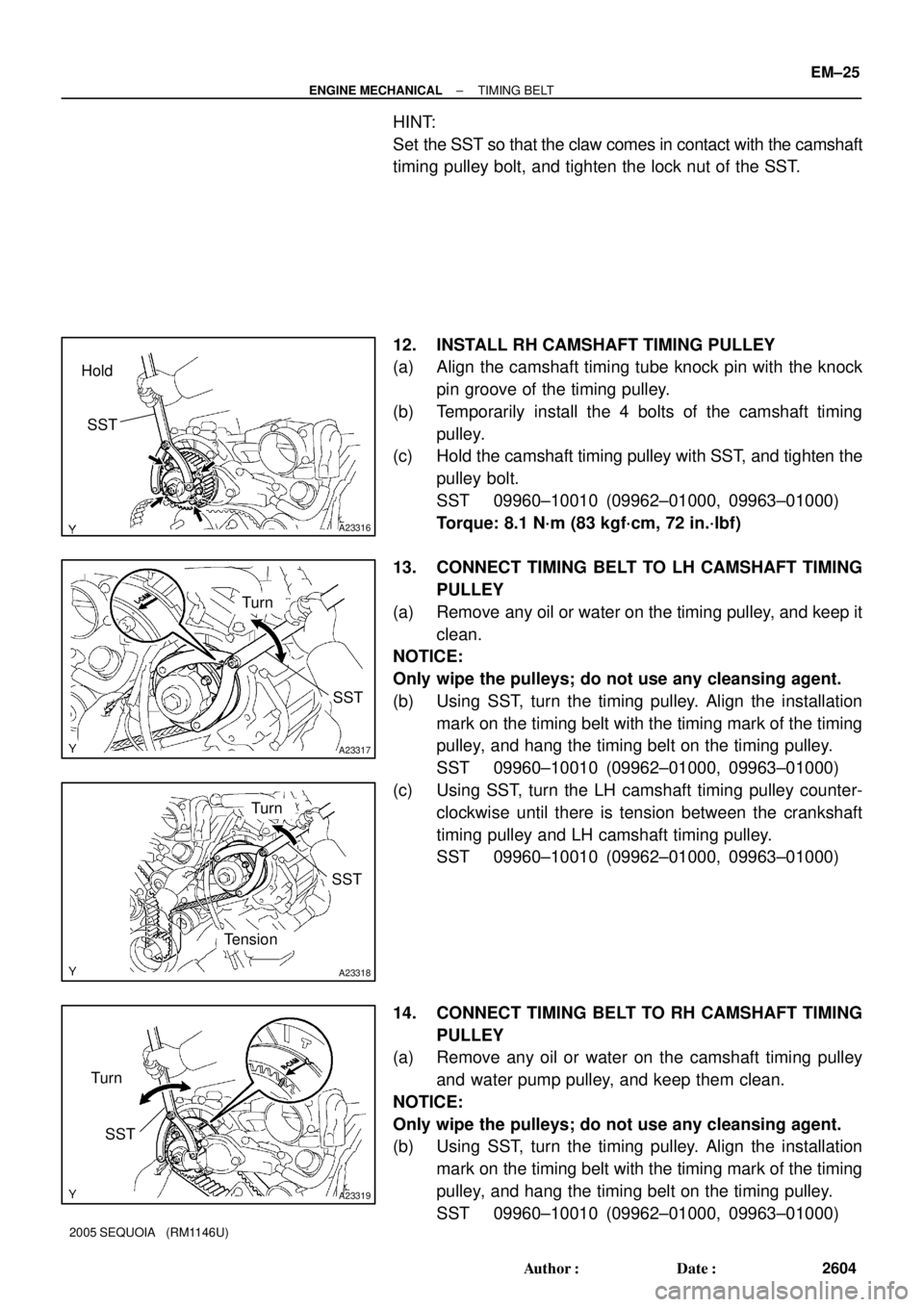
HINT:
Set the SST so that the claw comes in contact with the camshaft
timing pulley bolt, and tighten the lock nut of the SST.
12. INSTALL RH CAMSHAFT TIMING PULLEY
(a) Align the camshaft timing tube knock pin with the knock
pin groove of the timing pulley.
(b) Temporarily install the 4 bolts of the camshaft timing
pulley.
(c) Hold the camshaft timing pulley with SST, and tighten the
pulley bolt.
SST 09960±10010 (09962±01000, 09963±01000)
Torque: 8.1 N´m (83 kgf´cm, 72 in.´lbf)
13. CONNECT TIMING BELT TO LH CAMSHAFT TIMING
PULLEY
(a) Remove any oil or water on the timing pulley, and keep it
clean.
NOTICE:
Only wipe the pulleys; do not use any cleansing agent.
(b) Using SST, turn the timing pulley. Align the installation
mark on the timing belt with the timing mark of the timing
pulley, and hang the timing belt on the timing pulley.
SST 09960±10010 (09962±01000, 09963±01000)
(c) Using SST, turn the LH camshaft timing pulley counter-
clockwise until there is tension between the crankshaft
timing pulley and LH camshaft timing pulley.
SST 09960±10010 (09962±01000, 09963±01000)
14. CONNECT TIMING BELT TO RH CAMSHAFT TIMING
PULLEY
(a) Remove any oil or water on the camshaft timing pulley
and water pump pulley, and keep them clean.
NOTICE:
Only wipe the pulleys; do not use any cleansing agent.
(b) Using SST, turn the timing pulley. Align the installation
mark on the timing belt with the timing mark of the timing
pulley, and hang the timing belt on the timing pulley.
SST 09960±10010 (09962±01000, 09963±01000)