Page 2613 of 4323
P20636
1.27 mm
Hexagon Wrench
A04454
1.27 mm
Hexagon Wrench
A23307Turn
A23308
A23306
SST
EM±26
± ENGINE MECHANICALTIMING BELT
2605 Author�: Date�:
2005 SEQUOIA (RM1146U)
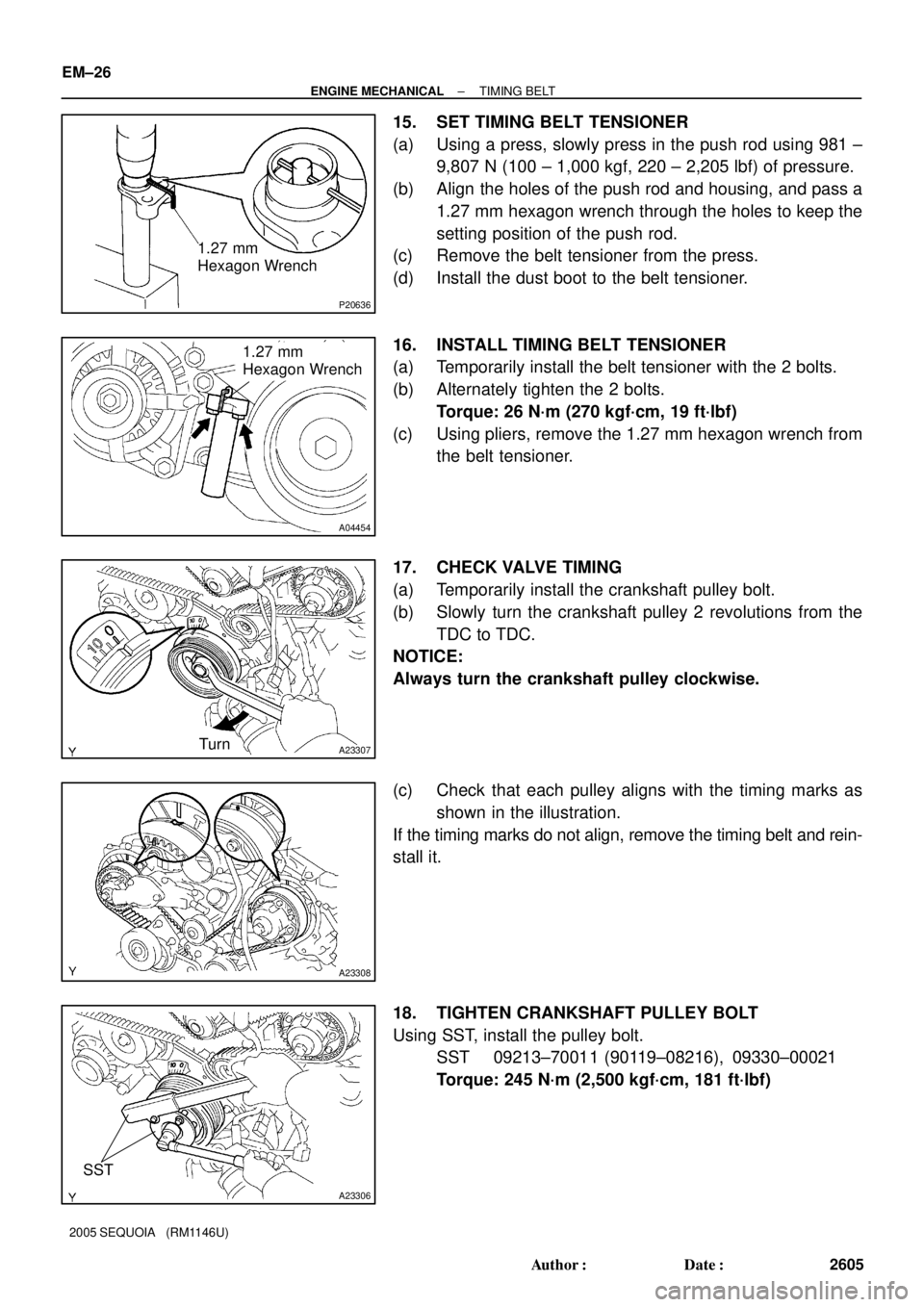
15. SET TIMING BELT TENSIONER
(a) Using a press, slowly press in the push rod using 981 ±
9,807 N (100 ± 1,000 kgf, 220 ± 2,205 lbf) of pressure.
(b) Align the holes of the push rod and housing, and pass a
1.27 mm hexagon wrench through the holes to keep the
setting position of the push rod.
(c) Remove the belt tensioner from the press.
(d) Install the dust boot to the belt tensioner.
16. INSTALL TIMING BELT TENSIONER
(a) Temporarily install the belt tensioner with the 2 bolts.
(b) Alternately tighten the 2 bolts.
Torque: 26 N´m (270 kgf´cm, 19 ft´lbf)
(c) Using pliers, remove the 1.27 mm hexagon wrench from
the belt tensioner.
17. CHECK VALVE TIMING
(a) Temporarily install the crankshaft pulley bolt.
(b) Slowly turn the crankshaft pulley 2 revolutions from the
TDC to TDC.
NOTICE:
Always turn the crankshaft pulley clockwise.
(c) Check that each pulley aligns with the timing marks as
shown in the illustration.
If the timing marks do not align, remove the timing belt and rein-
stall it.
18. TIGHTEN CRANKSHAFT PULLEY BOLT
Using SST, install the pulley bolt.
SST 09213±70011 (90119±08216), 09330±00021
Torque: 245 N´m (2,500 kgf´cm, 181 ft´lbf)
Page 2629 of 4323
A02859
A02850
SST
Service Bolt
Turn
A02861
A23341
Do Not Remove
A23342
10 mm
Hexagon
Wrench
EM±42
± ENGINE MECHANICALCYLINDER HEAD
2621 Author�: Date�:
2005 SEQUOIA (RM1146U)
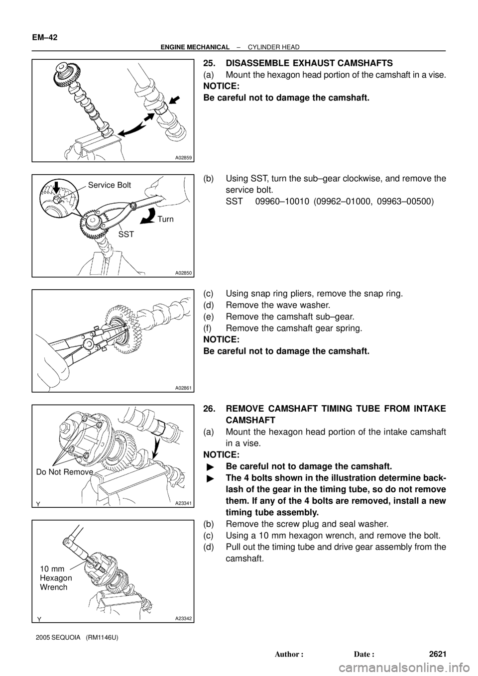
25. DISASSEMBLE EXHAUST CAMSHAFTS
(a) Mount the hexagon head portion of the camshaft in a vise.
NOTICE:
Be careful not to damage the camshaft.
(b) Using SST, turn the sub±gear clockwise, and remove the
service bolt.
SST 09960±10010 (09962±01000, 09963±00500)
(c) Using snap ring pliers, remove the snap ring.
(d) Remove the wave washer.
(e) Remove the camshaft sub±gear.
(f) Remove the camshaft gear spring.
NOTICE:
Be careful not to damage the camshaft.
26. REMOVE CAMSHAFT TIMING TUBE FROM INTAKE
CAMSHAFT
(a) Mount the hexagon head portion of the intake camshaft
in a vise.
NOTICE:
�Be careful not to damage the camshaft.
�The 4 bolts shown in the illustration determine back-
lash of the gear in the timing tube, so do not remove
them. If any of the 4 bolts are removed, install a new
timing tube assembly.
(b) Remove the screw plug and seal washer.
(c) Using a 10 mm hexagon wrench, and remove the bolt.
(d) Pull out the timing tube and drive gear assembly from the
camshaft.
Page 2650 of 4323
A02859
A02889
Service Bolt
SST
Sub Gear
Main Gear
Turn
A23353Front
A23343
5 mm Hexagon
Wrench SST
A03173
± ENGINE MECHANICALCYLINDER HEAD
EM±63
2642 Author�: Date�:
2005 SEQUOIA (RM1146U)
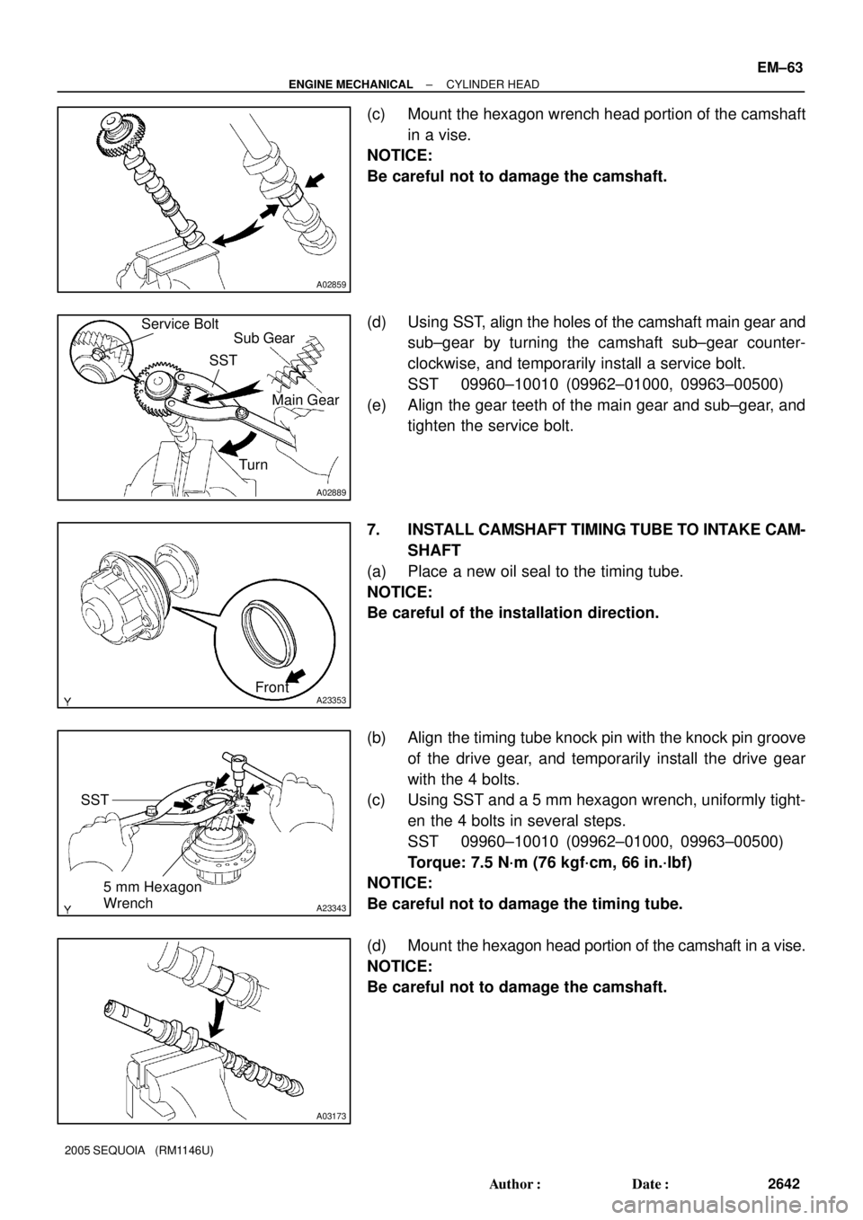
(c) Mount the hexagon wrench head portion of the camshaft
in a vise.
NOTICE:
Be careful not to damage the camshaft.
(d) Using SST, align the holes of the camshaft main gear and
sub±gear by turning the camshaft sub±gear counter-
clockwise, and temporarily install a service bolt.
SST 09960±10010 (09962±01000, 09963±00500)
(e) Align the gear teeth of the main gear and sub±gear, and
tighten the service bolt.
7. INSTALL CAMSHAFT TIMING TUBE TO INTAKE CAM-
SHAFT
(a) Place a new oil seal to the timing tube.
NOTICE:
Be careful of the installation direction.
(b) Align the timing tube knock pin with the knock pin groove
of the drive gear, and temporarily install the drive gear
with the 4 bolts.
(c) Using SST and a 5 mm hexagon wrench, uniformly tight-
en the 4 bolts in several steps.
SST 09960±10010 (09962±01000, 09963±00500)
Torque: 7.5 N´m (76 kgf´cm, 66 in.´lbf)
NOTICE:
Be careful not to damage the timing tube.
(d) Mount the hexagon head portion of the camshaft in a vise.
NOTICE:
Be careful not to damage the camshaft.
Page 2651 of 4323
A23342
10 mm Hexagon
Wrench
A14399
Timing Mark
Crankshaft
Pulley Bolt
Turn
Idler Pulley Bolt
A23354
B02636
Seal Packing EM±64
± ENGINE MECHANICALCYLINDER HEAD
2643 Author�: Date�:
2005 SEQUOIA (RM1146U)
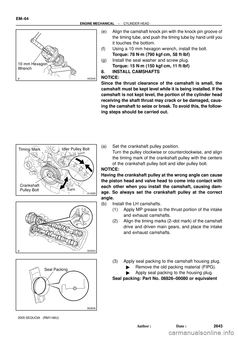
(e) Align the camshaft knock pin with the knock pin groove of
the timing tube, and push the timing tube by hand until you
it touches the bottom.
(f) Using a 10 mm hexagon wrench, install the bolt.
Torque: 78 N´m (790 kgf´cm, 58 ft´lbf)
(g) Install the seal washer and screw plug.
Torque: 15 N´m (150 kgf´cm, 11 ft´lbf)
8. INSTALL CAMSHAFTS
NOTICE:
Since the thrust clearance of the camshaft is small, the
camshaft must be kept level while it is being installed. If the
camshaft is not kept level, the portion of the cylinder head
receiving the shaft thrust may crack or be damaged, caus-
ing the camshaft to seize or break. To avoid this, the follow-
ing steps should be carried out.
(a) Set the crankshaft pulley position.
Turn the pulley clockwise or counterclockwise, and align
the timing mark of the crankshaft pulley with the centers
of the crankshaft pulley bolt and idler pulley bolt.
NOTICE:
Having the crankshaft pulley at the wrong angle can cause
the piston head and valve head to come into contact with
each other when you install the camshaft, causing dam-
age. So always set the crankshaft pulley at the correct
angle.
(b) Install the LH camshafts.
(1) Apply MP grease to the thrust portion of the intake
and exhaust camshafts.
(2) Align the timing marks (2±dot mark) of the camshaft
drive and driven main gears, and place the intake
and exhaust camshafts.
(3) Apply seal packing to the camshaft housing plug.
�Remove the old packing material (FIPG).
�Apply seal packing to the housing plug.
Seal packing: Part No. 08826±00080 or equivalent
Page 2712 of 4323
A04856
FrontPort
A08472
LH Side
A05132
Push
Wire
Clamp
New
O±Ring
± ENGINE MECHANICALCYLINDER BLOCK
EM±125
2704 Author�: Date�:
2005 SEQUOIA (RM1146U)
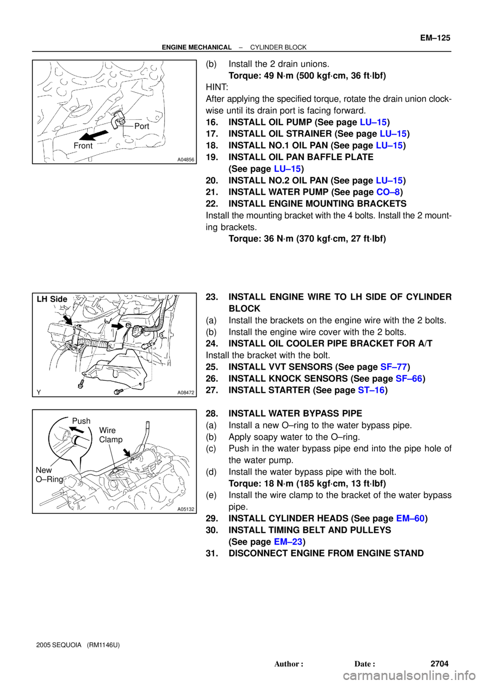
(b) Install the 2 drain unions.
Torque: 49 N´m (500 kgf´cm, 36 ft´lbf)
HINT:
After applying the specified torque, rotate the drain union clock-
wise until its drain port is facing forward.
16. INSTALL OIL PUMP (See page LU±15)
17. INSTALL OIL STRAINER (See page LU±15)
18. INSTALL NO.1 OIL PAN (See page LU±15)
19. INSTALL OIL PAN BAFFLE PLATE
(See page LU±15)
20. INSTALL NO.2 OIL PAN (See page LU±15)
21. INSTALL WATER PUMP (See page CO±8)
22. INSTALL ENGINE MOUNTING BRACKETS
Install the mounting bracket with the 4 bolts. Install the 2 mount-
ing brackets.
Torque: 36 N´m (370 kgf´cm, 27 ft´lbf)
23. INSTALL ENGINE WIRE TO LH SIDE OF CYLINDER
BLOCK
(a) Install the brackets on the engine wire with the 2 bolts.
(b) Install the engine wire cover with the 2 bolts.
24. INSTALL OIL COOLER PIPE BRACKET FOR A/T
Install the bracket with the bolt.
25. INSTALL VVT SENSORS (See page SF±77)
26. INSTALL KNOCK SENSORS (See page SF±66)
27. INSTALL STARTER (See page ST±16)
28. INSTALL WATER BYPASS PIPE
(a) Install a new O±ring to the water bypass pipe.
(b) Apply soapy water to the O±ring.
(c) Push in the water bypass pipe end into the pipe hole of
the water pump.
(d) Install the water bypass pipe with the bolt.
Torque: 18 N´m (185 kgf´cm, 13 ft´lbf)
(e) Install the wire clamp to the bracket of the water bypass
pipe.
29. INSTALL CYLINDER HEADS (See page EM±60)
30. INSTALL TIMING BELT AND PULLEYS
(See page EM±23)
31. DISCONNECT ENGINE FROM ENGINE STAND
Page 2722 of 4323
EC0NP±01
B16486
Clean Hose
Cylinder Head SideAir
B16487
Air
Intake
Manifold
SideClean Hose
B16488
Adhesive
B16484
Port
Front15 ± 25°
EC±6± EMISSION CONTROLPOSITIVE CRANKCASE VENTILATION (PCV)
SYSTEM
2714 Author�: Date�:
2005 SEQUOIA (RM1146U)
INSPECTION
1. REMOVE V±BANK COVER
2. INSPECT PCV VALVE
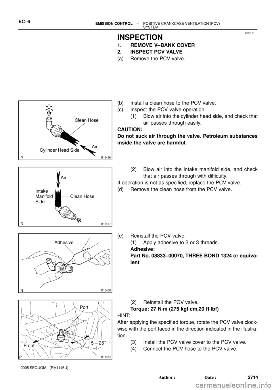
(a) Remove the PCV valve.
(b) Install a clean hose to the PCV valve.
(c) Inspect the PCV valve operation.
(1) Blow air into the cylinder head side, and check that
air passes through easily.
CAUTION:
Do not suck air through the valve. Petroleum substances
inside the valve are harmful.
(2) Blow air into the intake manifold side, and check
that air passes through with difficulty.
If operation is not as specified, replace the PCV valve.
(d) Remove the clean hose from the PCV valve.
(e) Reinstall the PCV valve.
(1) Apply adhesive to 2 or 3 threads.
Adhesive:
Part No. 08833±00070, THREE BOND 1324 or equiva-
lent
(2) Reinstall the PCV valve.
Torque: 27 N´m (275 kgf´cm,20 ft´lbf)
HINT:
After applying the specified torque, rotate the PCV valve clock-
wise with the port faced in the direction indicated in the illustra-
tion.
(3) Install the PCV valve cover to the PCV valve.
(4) Connect the PCV hose to the PCV valve.
Page 2773 of 4323
SF135±06
A01296
New Grommet
New O±Ring
B04439
OutwardTurn
Push
Connector
B17461
Fuel Return Pipe
B04438
Rotate
Outward
Connector
± SFIINJECTOR
SF±31
2765 Author�: Date�:
2005 SEQUOIA (RM1146U)
INSTALLATION
1. INSTALL INJECTORS AND DELIVERY PIPES
NOTICE:
�Be careful not to drop the injectors when installing
the delivery pipes.
�Do not apply any load to the injector on horizontal
direction.
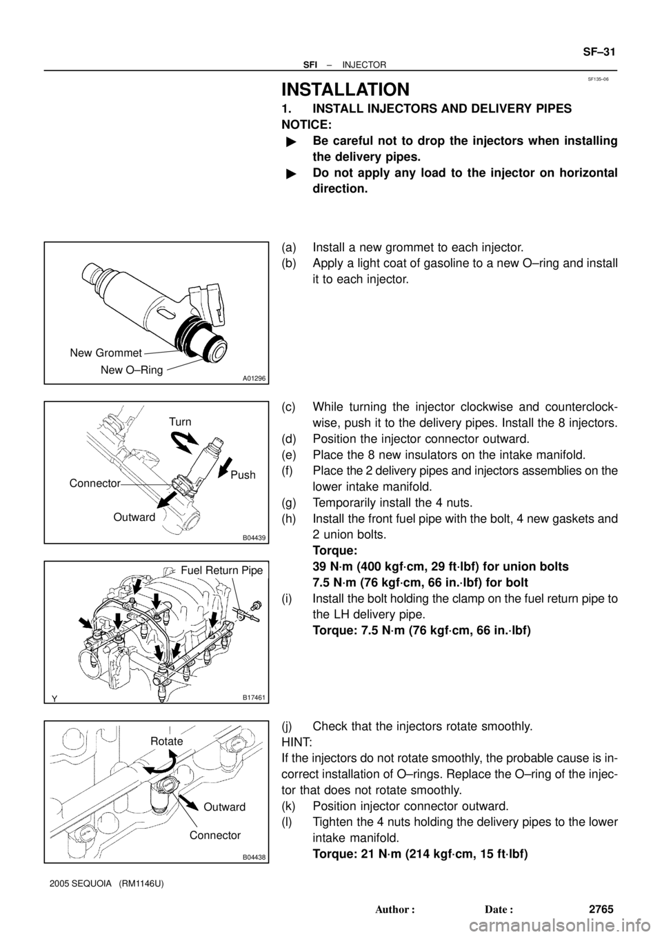
(a) Install a new grommet to each injector.
(b) Apply a light coat of gasoline to a new O±ring and install
it to each injector.
(c) While turning the injector clockwise and counterclock-
wise, push it to the delivery pipes. Install the 8 injectors.
(d) Position the injector connector outward.
(e) Place the 8 new insulators on the intake manifold.
(f) Place the 2 delivery pipes and injectors assemblies on the
lower intake manifold.
(g) Temporarily install the 4 nuts.
(h) Install the front fuel pipe with the bolt, 4 new gaskets and
2 union bolts.
Torque:
39 N´m (400 kgf´cm, 29 ft´lbf) for union bolts
7.5 N´m (76 kgf´cm, 66 in.´lbf) for bolt
(i) Install the bolt holding the clamp on the fuel return pipe to
the LH delivery pipe.
Torque: 7.5 N´m (76 kgf´cm, 66 in.´lbf)
(j) Check that the injectors rotate smoothly.
HINT:
If the injectors do not rotate smoothly, the probable cause is in-
correct installation of O±rings. Replace the O±ring of the injec-
tor that does not rotate smoothly.
(k) Position injector connector outward.
(l) Tighten the 4 nuts holding the delivery pipes to the lower
intake manifold.
Torque: 21 N´m (214 kgf´cm, 15 ft´lbf)
Page 2850 of 4323
LU08Q±10
B05837
Pull O±Ring
B05838
LU±8
± LUBRICATIONOIL PUMP
2842 Author�: Date�:
2005 SEQUOIA (RM1146U)
REMOVAL
HINT:
When repairing the oil pump, the oil pan and strainer should be
removed and cleaned.
1. REMOVE ENGINE FROM VEHICLE
(2WD: See page EM±79)
(4WD: See page EM±92)
2. INSTALL ENGINE TO ENGINE STAND FOR DIS-
ASSEMBLY
3. REMOVE TIMING BELT (See page EM±16)
4. REMOVE NO.1 IDLER PULLEY (See page EM±16)
5. REMOVE NO.2 IDLER PULLEY (See page EM±16)
6. REMOVE CRANKSHAFT TIMING PULLEY
(See page EM±16)
7. REMOVE CRANKSHAFT POSITION SENSOR
(See page IG±11)
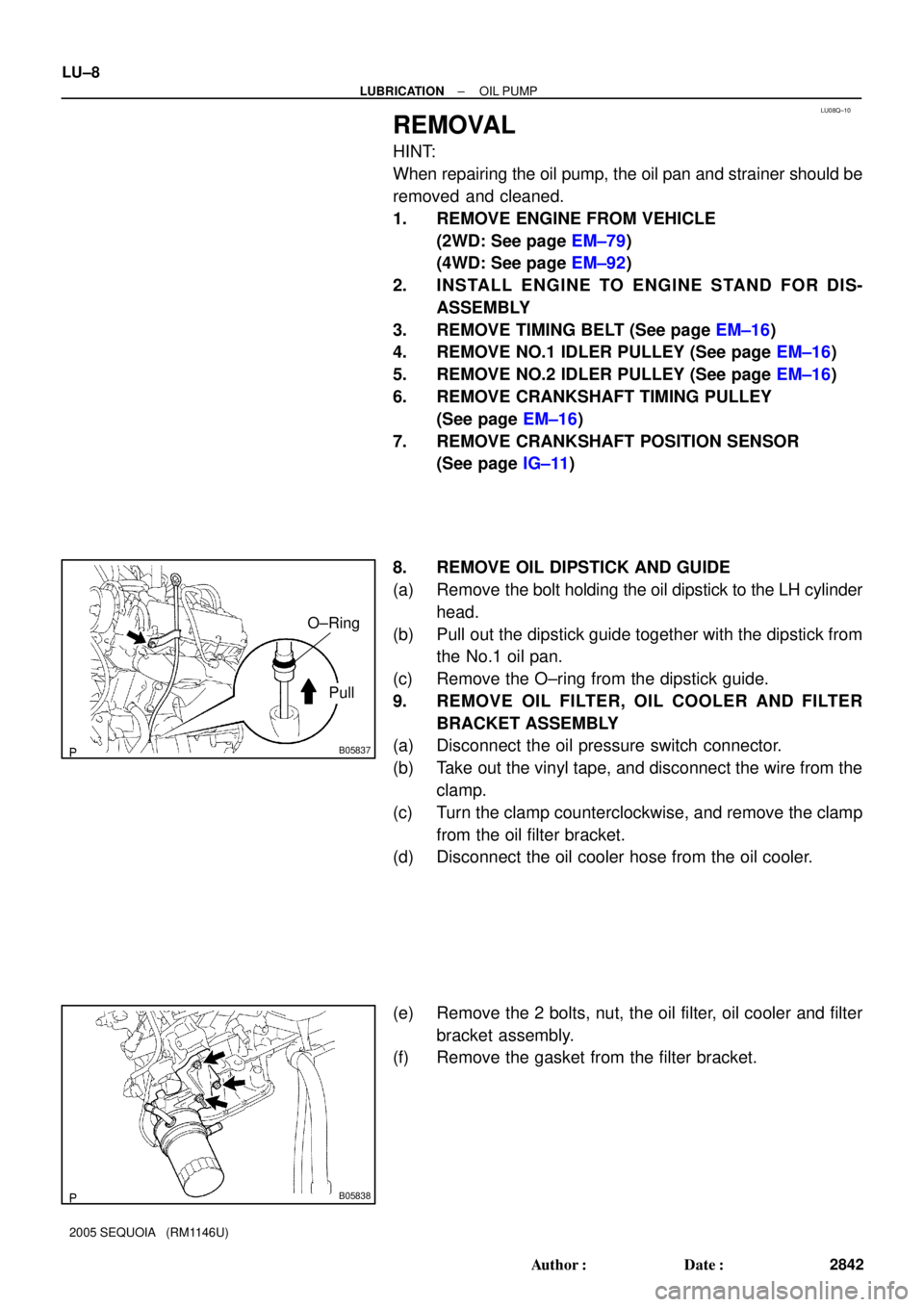
8. REMOVE OIL DIPSTICK AND GUIDE
(a) Remove the bolt holding the oil dipstick to the LH cylinder
head.
(b) Pull out the dipstick guide together with the dipstick from
the No.1 oil pan.
(c) Remove the O±ring from the dipstick guide.
9. REMOVE OIL FILTER, OIL COOLER AND FILTER
BRACKET ASSEMBLY
(a) Disconnect the oil pressure switch connector.
(b) Take out the vinyl tape, and disconnect the wire from the
clamp.
(c) Turn the clamp counterclockwise, and remove the clamp
from the oil filter bracket.
(d) Disconnect the oil cooler hose from the oil cooler.
(e) Remove the 2 bolts, nut, the oil filter, oil cooler and filter
bracket assembly.
(f) Remove the gasket from the filter bracket.