Page 3465 of 4323
BE17A±06
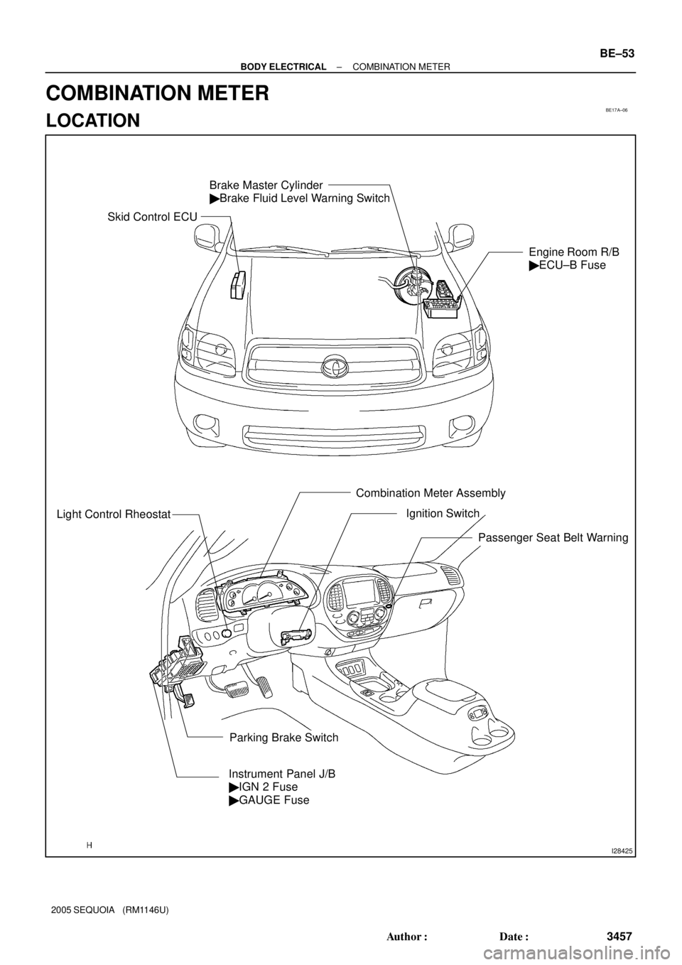
I28425
Brake Master Cylinder
� Brake Fluid Level Warning Switch
Engine Room R/B
� ECU±B Fuse
Light Control Rheostat
Combination Meter Assembly
Instrument Panel J/B
� IGN 2 Fuse
� GAUGE Fuse
Parking Brake SwitchIgnition Switch
Passenger Seat Belt Warning
Skid Control ECU
± BODY ELECTRICALCOMBINATION METER
BE±53
3457 Author�: Date�:
2005 SEQUOIA (RM1146U)
COMBINATION METER
LOCATION
Page 3469 of 4323

I01279
Warning Light
Ignition
Switch
Battery
I19428
21OFF
ON
N01212
BE1217
Warning Light
Ignition
Switch
Battery
± BODY ELECTRICALCOMBINATION METER
BE±57
3461 Author�: Date�:
2005 SEQUOIA (RM1146U)
7. INSPECT BRAKE WARNING LIGHT OPERATION
(a) Disconnect the connector from the brake fluid warning
switch.
(b) Release the parking brake pedal.
(c) Connect the terminals on the harness side of the level
warning switch connector.
(d) Start the engine and check that the warning light comes
on.
If the warning light does not come on, test the bulb or wire har-
ness.
8. INSPECT BRAKE FLUID LEVEL WARNING SWITCH
CONTINUITY
(a) Remove the reservoir tank cap and strainer.
(b) Disconnect the connector.
(c) Check that no continuity exists between the terminals with
the switch OFF (float up).
(d) Use siphon, etc. to drain fluid out of the reservoir tank.
(e) Check that continuity exists between the terminals with
the switch ON (float down).
(f) Pour the fluid back in the reservoir tank.
If continuity is not as specified, replace the switch.
9. INSPECT PARKING BRAKE SWITCH CONTINUITY
(a) Check that continuity exists between the terminal and
switch body with the switch ON (switch pin released).
(b) Check that no continuity exists between the terminal and
switch body with the switch OFF (switch pin pushed in).
If operation is not as specified, replace the switch or inspect
ground point.
10. INSPECT WASHER LEVEL WARNING LIGHT OPERA-
TION
(a) Disconnect the connectors from the combination meter.
(b) Connect the negative (±) lead from the battery to terminal
16.
(c) Turn the ignition switch ON and check that the warning
light comes on.
If the warning light does not come on, test the bulb.
Page 3559 of 4323
BE26G±04
I28424
Engine Room J/B
� TOWING Fuse
Trailer Socket
Towing Converter Relay
(Located inside of the quarter trim panel LH)
Engine Room R/B No. 3
� BATT CHARGE Relay
� TOWING TAIL Relay
� TOWING BRK Fuse
� TOWING TAIL Fuse
Brake Controller
(Located inside of the cowl side trim board LH)
± BODY ELECTRICALTRAILER TOWING
BE±147
3551 Author�: Date�:
2005 SEQUOIA (RM1146U)
TRAILER TOWING
LOCATION
Page 3560 of 4323

INSPECTION
1. INSPECT TOWING CONVERTER CIRCUIT
Remove the towing converter wi")
BE2D5±02
I24381
Wire Harness Side: BE±148
± BODY ELECTRICALTRAILER TOWING
3552 Author�: Date�:
2005 SEQUOIA (RM1146U)
INSPECTION
1. INSPECT TOWING CONVERTER CIRCUIT
Remove the towing converter with the connector still connected
and inspect the wire harness side connector from the back side,
as shown in the table below.
Tester connectionConditionSpecified condition
4 ± 6Turn signal switch LEFT or hazard warning switch ON10 ± 14 V e 0 V
4 ± 6Turn signal switch LEFT and stop light switch ON (Brake pedal depressed)10 ± 14 V e 0 V
4 ± 6Turn signal switch OFF, hazard warning switch OFF and stop light switch OFF
(Brake pedal released)0 V
4 ± 6Stop light switch ON (Brake pedal depressed)10 ± 14 V
6 ± 9Turn signal switch LEFT or hazard warning switch ON10 ± 14 V e 0 V
6 ± 9Turn signal switch OFF or RIGHT and hazard warning switch OFF0 V
6 ± Body groundAlwaysContinuity
2 ± 6Turn signal switch RIGHT or hazard warning switch ON10 ± 14 V e 0 V
2 ± 6Turn signal switch RIGHT and stop light switch ON (Brake pedal depressed)10 ± 14 V e 0 V
26Turn signal switch OFF, and hazard warning switch OFF and stop light switch OFF0V2 ± 6Turn signal switch OFF, and hazard warning switch OFF and sto light switch OFF
(Brake pedal released)0 V
2 ± 6Stop light switch ON (Brake pedal depressed)10 ± 14 V e 0 V
1 ± 6Always10 ± 14 V
6 ± 8Stop light switch ON (Brake pedal depressed)10 ± 14 V
6 ± 8Stop light switch OFF (Brake pedal released)0 V
3 ± 6Turn signal switch RIGHT or hazard warning switch ON10 ± 14 V e 0 V
3 ± 6Turn signal switch OFF or LEFT and hazard warning switch OFF0 V
If the circuit is not as specified, inspect the circuit connected to
other parts.
Page 3561 of 4323

2. Trailer Socket 7 Pin Type:
INSPECT BRAKE CONTROLLER")
I24379
Wire Harness Side:
I18635
1
2 34
5
I18635
1
2 34
5
± BODY ELECTRICALTRAILER TOWING
BE±149
3553 Author�: Date�:
2005 SEQUOIA (RM1146U)
2. Trailer Socket 7 Pin Type:
INSPECT BRAKE CONTROLLER CIRCUIT
Remove the brake controller with the connector still connected
and inspect the wire harness side connector from the back side,
as shown in the table below.
Tester connectionConditionSpecified condition
1 ± 3Stop light switch ON (Brake pedal depressed)10 ± 14 V
1 ± 3Stop light switch OFF (Brake pedal released)0 V
2 ± 3Always10 ± 14 V
3 ± 4Stop light switch ON (Brake pedal depressed)10 ± 14 V
3 ± 4Stop light switch OFF (Brake pedal released)0 V
3 ± 5Light control switch TAIL or HEAD10 ± 14 V
3 ± 5Light control switch OFF0 V
If the circuit is not as specified, inspect the circuit connected to
other parts.
3. INSPECT TOWING TAIL RELAY CONTINUITY
ConditionTester connectionSpecified condition
Always1 ± 2Continuity
Always3 ± 5No continuity
Apply B+ between
terminals 1 and 2.3 ± 5Continuity
If continuity is not as specified, replace the relay.
4. INSPECT BATT CHARGE RELAY CIRCUIT
ConditionTester connectionSpecified condition
Always1 ± 2Continuity
Always3 ± 5No continuity
Apply B+ between
terminals 1 and 2.3 ± 5Continuity
If continuity is not as specified, replace the relay.
Page 3722 of 4323

INSPECTION
CAUTION:
Replace the seat belt assembly (outer belt, inner belt, bolts,
nuts or sill")
BO47P±01
BO0632
BO0633
15°
45°
± BODYSEAT BELT
BO±161
3714 Author�: Date�:
2005 SEQUOIA (RM1146U)
INSPECTION
CAUTION:
Replace the seat belt assembly (outer belt, inner belt, bolts,
nuts or sill±bar) if it has been used in a severe impact. The
entire assembly should be replaced even if damage is not
obvious.
1. RUNNING TEST (IN SAFE AREA)
(a) Fasten the front seat belts.
(b) Drive the car at 10 mph (16 km/h) and slam on the brakes.
Check that the belt locks and cannot be extended at this
time.
HINT:
Conduct this test in a safe area. If the belt does not lock, remove
the belt mechanism assembly and conduct the following static
check. Also, whenever installing a new belt assembly, verify the
proper operation before installation.
2. Driver 's seat belt (ELR):
STATIC TEST
(a) Make sure that the belt locks when pulled out quickly.
(b) Remove the locking retractor assembly.
HINT:
Before removing the pretensioner connector, be sure to read
the precautionary notice in the RS section.
(c) Tilt the retractor slowly.
(d) Make sure that the belt can be pulled out at a tilt of 15 de-
grees or less, and cannot be pulled out over 45 degrees
of tilt.
If a problem is found, replace the assembly.
3. Except driver's seat belt (ELR/ALR):
STATIC TEST
(a) Make sure that the belt locks when pulled out quickly.
(b) Pull out the whole belt, then retract the belt slightly and
pull it out again
(c) Make sure that the belt cannot be extended further.
If a problem is found, replace the assembly.
(d) Remove the locking retractor assembly.
HINT:
Front passenger's seat belt only:
Before removing the pretensioner connector, be sure to read
the precautionary notice in the RS section.
(e) Tilt the retractor slowly.
Page 3853 of 4323

iv
2005 SEQUOIA from Aug. 04 Prod. (OM34424U)
In order to be effective, the SRS airbags must deploy with
tremendous speed. The rapid deployment of the SRS air-
bags makes the")
05_SEQUOIA_U (L/O 0408)
iv
2005 SEQUOIA from Aug. '04 Prod. (OM34424U)
In order to be effective, the SRS airbags must deploy with
tremendous speed. The rapid deployment of the SRS air-
bags makes the SRS airbags themselves potential sources
of serious injury if an occupant is too close to an airbag,
or if an object or some part of his or her body has been
placed between the occupant and the airbag at the time of
deployment. This is just one example of how the instruc-
tions in Section 1±3 of this Owner 's Manual will help en-
sure proper use of the occupant restraint systems, and
increase the safety they can provide to you and your fami-
ly in the event of an accident.
Toyota recommends you to read the provisions in Section
1±3 carefully and refer to them as needed during your time
of ownership of this vehicle.Event data recorder
Your vehicle has computers that monitor and control cer-
tain aspects of your vehicle. These computers assist in
driving and maintaining optimal vehicle performance. Be-
sides storing data useful for troubleshooting, there is a
system to record data in a crash or a near car crash
event. This is called an Event Data Recorder (EDR).
The SRS airbag sensor assembly contains the EDR. In a
crash or a near car crash event, this device records some
or all of the following information:
�Engine speed
�Whether the brake pedal was applied or not
�Vehicle speed
�To what extent the accelerator pedal was depressed
�Position of the transmission selector lever
�Whether the driver and front passenger wore the seat
belts or not
�Driver 's seat position
�Front passenger 's occupant classification
Page 3856 of 4323
05_SEQUOIA_U (L/O 0408)
vii
2005 SEQUOIA from Aug. '04 Prod. (OM34424U)
Spark ignition system of your
To y o t a
The spark ignition system in your Toyota meets all re-
quirements of the Canadian Interference±Causing Equip-
ment Standard.
Installation of a mobile
two±way radio system
As the installation of a mobile two±way radio system in
your vehicle could affect electronic systems such as
multiport fuel injection system/sequential multiport fuel
injection system, electronic throttle control system,
cruise control system, anti±lock brake system, traction
control system (two±wheel drive models)/active traction
control system (four±wheel drive models), vehicle stabil-
ity control system, rear height control air suspension
system, tire pressure warning system, SRS airbag sys-
tem and seat belt pretensioner system, be sure to
check with your Toyota dealer for precautionary mea-
sures or special instructions regarding installation.


vii
2005 SEQUOIA from Aug. 04 Prod. (OM34424U)
Spark ignition system of your
To y o t a
The spark ignition system in your Toyota meets all re-
quirements of the Canadian Inter")