Page 3233 of 4323
BR0A5±05
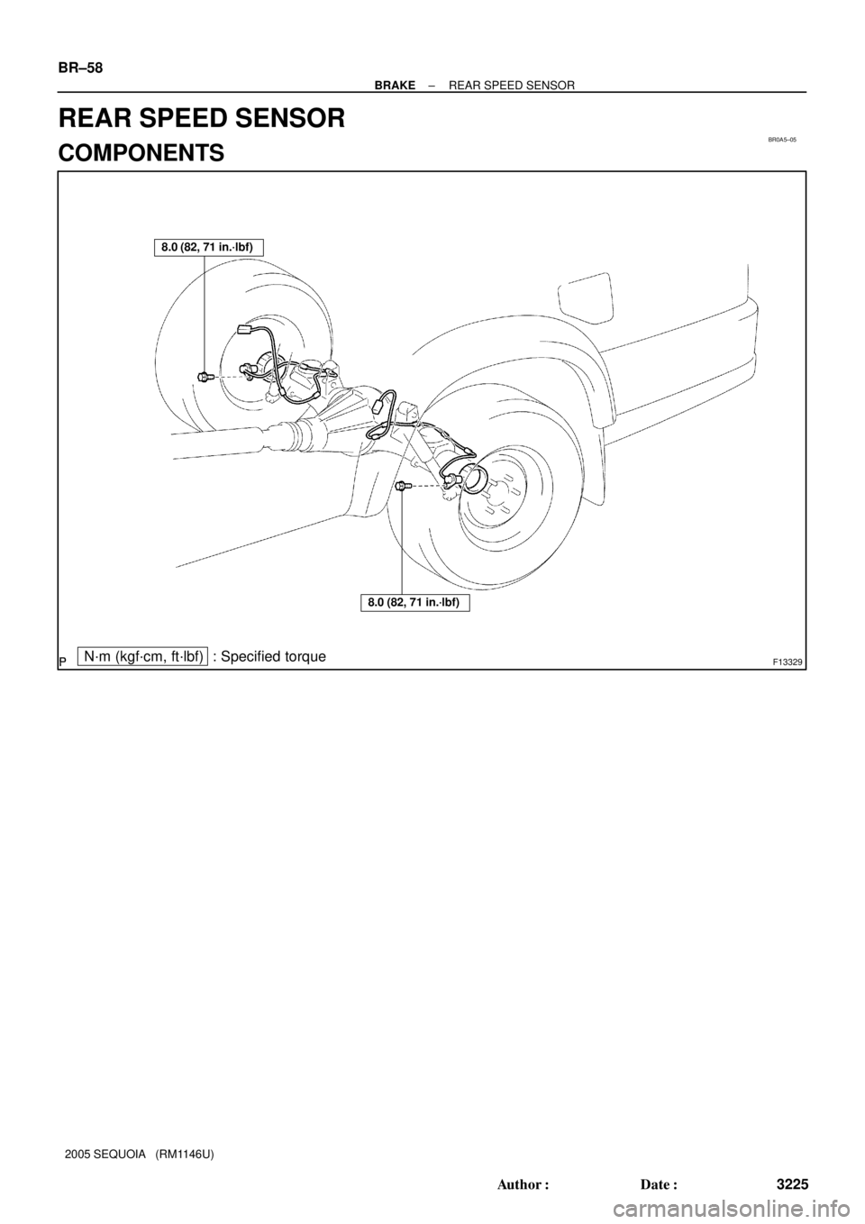
F13329N´m (kgf´cm, ft´lbf) : Specified torque
8.0 (82, 71 in.´lbf)
8.0 (82, 71 in.´lbf)
BR±58
± BRAKEREAR SPEED SENSOR
3225 Author�: Date�:
2005 SEQUOIA (RM1146U)
REAR SPEED SENSOR
COMPONENTS
Page 3234 of 4323
BR0A6±04
F13328
± BRAKEREAR SPEED SENSOR
BR±59
3226 Author�: Date�:
2005 SEQUOIA (RM1146U)
REMOVAL
1. DISCONNECT SPEED SENSOR CONNECTOR
2. REMOVE SPEED SENSOR
(a) Remove the 6 resin clips holding the sensor wire harness.
(b) Remove the bolt and speed sensor from the axle carrier.
Torque: 8.0 N´m (82 kgf´cm, 71 in.´lbf)
Page 3235 of 4323
BR0A7±07
BR±60
± BRAKEREAR SPEED SENSOR
3227 Author�: Date�:
2005 SEQUOIA (RM1146U)
INSTALLATION
Installation is in the reverse order of removal (See page BR±59).
HINT:
After installation, check speed sensor signal (See page DI±899).
Page 3247 of 4323
SR1F3±03
F17895
Steering Wheel Pad
Steering
Wheel
Column Lower
CoverCombination
SwitchSteering Column Assembly
Transmission Control
Cable Assembly
Lower LH Finish PanelColumn Hole
Cover No. 2
No. 2 Universal
Joint Assembly
No. 2 Heater to Register Dust Torx® Screw
35 (360, 26)
35 (360, 26)
8.0 (82, 71 in.´lbf)
26 (260, 19)
26 (260, 19)
8.8 (90, 78 in.´lbf)
50 (510, 37)
8.8 (90, 78 in.´lbf)
Front Door Scuff PlateCowl Side Trim
Hood Lock
Release Lever
8.0 (82, 71 in.´lbf)
Side Panel
No. 2 Intermediate
Shaft AssemblyBrake Pedal
Return Spring
Column Upper Cover
N´m (kgf´cm, ft´lbf): Specified torque
Steering Wheel Lower
No. 3 Cover
Steering Wheel Lower
No. 2 Cover
35 (360, 26)
Sliding Yoke
Torx® Screw SR±12
± STEERINGTILT STEERING COLUMN
3239 Author�: Date�:
2005 SEQUOIA (RM1146U)
TILT STEERING COLUMN
COMPONENTS
Page 3250 of 4323

5. REMOVE COMBINATION SWITCH WITH SPIRAL
CABLE
(a) Disconnect the 4 connectors.")
F17896
A
BMatchmarks
F13260
F06703
± STEERINGTILT STEERING COLUMN
SR±15
3242 Author�: Date�:
2005 SEQUOIA (RM1146U)
5. REMOVE COMBINATION SWITCH WITH SPIRAL
CABLE
(a) Disconnect the 4 connectors.
(b) Disconnect the airbag connector.
(c) Remove the 3 screws and combination switch.
6. REMOVE SPIRAL CABLE (See page BE±26)
NOTICE:
Do not disassemble the cable or apply oil to it.
7. REMOVE COWL SIDE TRIM AND FRONT DOOR
SCUFF PLATE
8. REMOVE LOWER LH FINISH PANEL
(a) Remove the 2 screws and disconnect the hood lock re-
lease lever from the panel.
(b) Remove the 4 panel set bolts and lower LH finish panel.
9. REMOVE NO. 2 HEATER TO REGISTER DUCT
10. REMOVE BRAKE PEDAL RETURN SPRING
11. REMOVE SLIDING YOKE
(a) Put matchmarks on the sliding yoke and No. 2 intermedi-
ate shaft assembly.
(b) Remove the ºAº bolt.
(c) Remove the ºBº bolt.
(d) Slide the sliding yoke and remove it.
12. REMOVE COLUMN HOLE COVER NO. 2
Remove the 3 bolts and column hole cover No. 2.
13. DISCONNECT TRANSMISSION CONTROL CABLE
ASSEMBLY
Disconnect the cable assembly from the column shift lever as-
sembly.
14. REMOVE STEERING COLUMN ASSEMBLY WITH
NO. 2 UNIVERSAL JOINT ASSEMBLY
(a) Disconnect the connectors.
(b) Remove the 4 steering column set nuts.
(c) Pull out the steering column assembly with the No. 2 uni-
versal joint assembly connected.
Page 3259 of 4323

5. INSTALL COLUMN HOLE COVER NO. 2
Install the column hole cover No. 2 to t")
F13260
F17896
BMatchmarks
A
F19948
Mark
SR±24
± STEERINGTILT STEERING COLUMN
3251 Author�: Date�:
2005 SEQUOIA (RM1146U)
5. INSTALL COLUMN HOLE COVER NO. 2
Install the column hole cover No. 2 to the body with the 3 bolts.
Torque: 8.0 N´m (82 kgf´cm, 71 in.´lbf)
6. INSTALL SLIDING YOKE
(a) Align the matchmark on the sliding yoke with the one on
the No. 2 intermediate shaft assembly.
(b) Install the ºBº bolt.
Torque: 35 N´m (360 kgf´cm, 26 ft´lbf)
(c) Install the ºAº bolt.
Torque: 35 N´m (360 kgf´cm, 26 ft´lbf)
7. INSTALL BRAKE PEDAL RETURN SPRING
8. INSTALL NO. 2 HEATER TO REGISTER DUCT
9. INSTALL LOWER LH FINISH PANEL
(a) Install the lower LH finish panel with the 4 bolts.
(b) Connect the hood lock release lever with the 2 screws.
10. INSTALL COWL SIDE TRIM AND FRONT DOOR
SCUFF PLATE
11. INSTALL SPIRAL CABLE (See page BE±26)
12. INSTALL COMBINATION SWITCH WITH SPIRAL
CABLE
(a) Install the combination switch with the 3 screws.
(b) Connect the airbag connector.
(c) Connect the 4 connectors.
13. INSTALL UPPER AND LOWER COLUMN COVERS
Install the upper and lower column covers with the 3 screws.
14. CENTER SPIRAL CABLE
(a) Check that the front wheels are facing straight ahead.
(b) Turn the cable counterclockwise by hand until it feels firm.
(c) Then rotate the cable clockwise about 2.5 turns to align
the marks.
HINT:
The cable will rotate about 2.5 turns to both the left and right
from the center.
Page 3417 of 4323
 Taillight does not go off when light control switch is in OFF posi-
tion.
1. TAILLIGHT Relay
2. Light Control Swit")
± BODY ELECTRICALTROUBLESHOOTING
BE±5
3409 Author�: Date�:
2005 SEQUOIA (RM1146U) Taillight does not go off when light control switch is in OFF posi-
tion.
1. TAILLIGHT Relay
2. Light Control Switch
3. Wire Harness
4. Body ECUBE±27
BE±27
±
±
Headlight does not come on when engine is running and light
control switch is in OFF position .
1. ECU±B Fuse
2. MAIN Fuse
3. HEAD Relay
4. DRL Fuse
5. DRL No. 4 Relay
6. DIMMER Relay
7. Parking Brake Switch
8. Wire Harness
9. Body ECUBE±14
BE±14
BE±27
BE±14
BE±27
BE±55
BE±55
±
±
FOG LIGHT SYSTEM
This system uses the multiplex communication system, so check diagnosis system of the multiplex commu-
nication system before you proceed with troubleshooting.
SymptomSuspect AreaSee page
Fog light does not come on with light control switch is in HEAD
position.
(Headlight is normal.)
1. FOG Fuse
2. FOG LIGHT Relay
3. Fog Light Switch
4. Wire Harness
5. Body ECUBE±14
BE±27
BE±34
±
±
Fog light does not come on with light control switch is in HEAD
position.
(Headlight does not light).1.*1 Other Parts
2. Wire Harness±
±
Only one light does not come on.1. Bulb
2. Wire Harness±
±
*1: Inspect Headlight System
TURN SIGNAL AND HAZARD WARNING SYSTEM
SymptomSuspect AreaSee page
ºHazardº and ºTurnº do not light up.
1. GAUGE Fuse
2. TURN±HAZ Fuse
3. Ignition Switch
4. Turn Signal Flasher Relay
5. Wire HarnessBE±14
BE±14
BE±24
BE±24
±
Hazard warning light does not light up.
(Turn is normal)1. Hazard Warning Switch
2. Wire Harness
3. Turn Signal Flasher RelayBE±36
±
BE±36
Turn signal does not light up.
(Hazard is normal)1. Turn Signal Switch
2. Wire Harness
3. Turn Signal Flasher RelayBE±36
±
BE±36
Turn signal does not light up in one direction.1. Bulb
2. Wire Harness±
±
Only one bulb does not light up.1. Bulb
2. Wire Harness±
±
INTERIOR LIGHT SYSTEM
This system uses the multiplex communication system, so check diagnosis system of the multiplex commu-
nication system before you proceed with troubleshooting.
SymptomSuspect AreaSee page
All the interior lights do not come on.
1. DOME Fuse
2. Illumination Circuit
3. Body ECUBE±14
DI±1759
±
Page 3425 of 4323
± BODY ELECTRICALTROUBLESHOOTING
BE±13
3417 Author�: Date�:
2005 SEQUOIA (RM1146U)
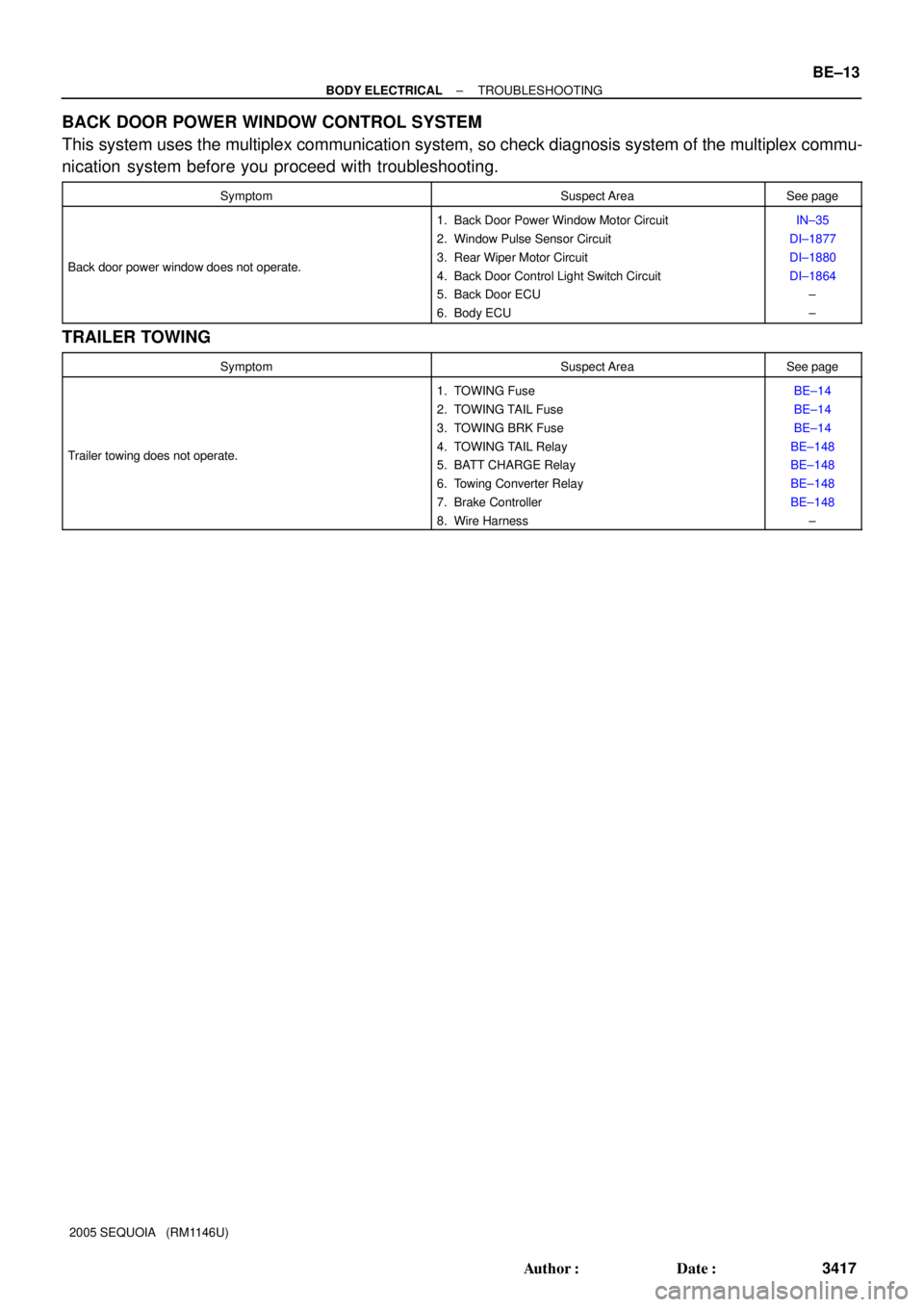
BACK DOOR POWER WINDOW CONTROL SYSTEM
This system uses the multiplex communication system, so check diagnosis system of the multiplex commu-
nication system before you proceed with troubleshooting.
SymptomSuspect AreaSee page
Back door power window does not operate.
1. Back Door Power Window Motor Circuit
2. Window Pulse Sensor Circuit
3. Rear Wiper Motor Circuit
4. Back Door Control Light Switch Circuit
5. Back Door ECU
6. Body ECUIN±35
DI±1877
DI±1880
DI±1864
±
±
TRAILER TOWING
SymptomSuspect AreaSee page
Trailer towing does not operate.
1. TOWING Fuse
2. TOWING TAIL Fuse
3. TOWING BRK Fuse
4. TOWING TAIL Relay
5. BATT CHARGE Relay
6. Towing Converter Relay
7. Brake Controller
8. Wire HarnessBE±14
BE±14
BE±14
BE±148
BE±148
BE±148
BE±148
±