Page 3376 of 4323
RS0BO±11
H23231
± SUPPLEMENTAL RESTRAINT SYSTEMAIRBAG SENSOR ASSEMBLY
RS±85
3368 Author�: Date�:
2005 SEQUOIA (RM1146U)
INSTALLATION
NOTICE:
�Never use SRS parts from another vehicle. When re-
placing parts, replace them with new ones.
�Never reuse the airbag sensor assembly involved in
a collision when the airbag has deployed.
�If the airbag sensor assembly center has been
dropped, or there are any cracks, dents or other de-
fects in the case, bracket or connector, replace it with
a new one.
�When installing the airbag sensor assembly center,
be careful that the SRS wiring does not interfere with
other parts and that it is not pinched between other
parts.
�After installing, shake the airbag sensor assembly to
check that there is no looseness.
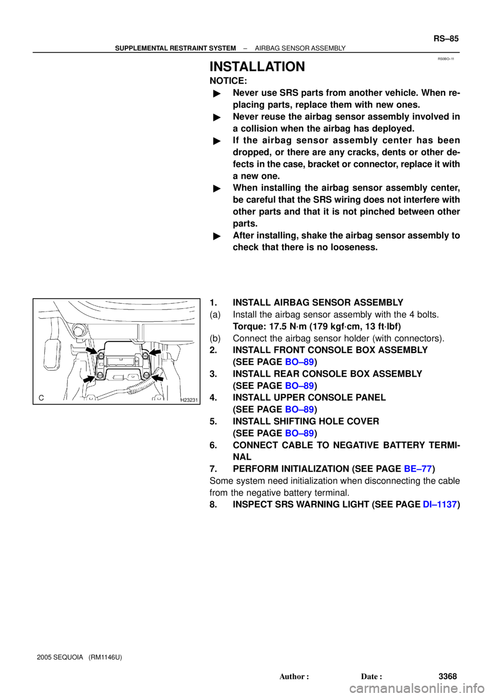
1. INSTALL AIRBAG SENSOR ASSEMBLY
(a) Install the airbag sensor assembly with the 4 bolts.
Torque: 17.5 N´m (179 kgf´cm, 13 ft´lbf)
(b) Connect the airbag sensor holder (with connectors).
2. INSTALL FRONT CONSOLE BOX ASSEMBLY
(SEE PAGE BO±89)
3. INSTALL REAR CONSOLE BOX ASSEMBLY
(SEE PAGE BO±89)
4. INSTALL UPPER CONSOLE PANEL
(SEE PAGE BO±89)
5. INSTALL SHIFTING HOLE COVER
(SEE PAGE BO±89)
6. CONNECT CABLE TO NEGATIVE BATTERY TERMI-
NAL
7. PERFORM INITIALIZATION (SEE PAGE BE±77)
Some system need initialization when disconnecting the cable
from the negative battery terminal.
8. INSPECT SRS WARNING LIGHT (SEE PAGE DI±1137)
Page 3381 of 4323
H23879
RS11I±01
RS±90
± SUPPLEMENTAL RESTRAINT SYSTEMFRONT AIRBAG SENSOR
3373 Author�: Date�:
2005 SEQUOIA (RM1146U)
INSTALLATION
HINT:
�Use the same procedures for the RH side and LH side.
�The procedures listed below are for the LH side.
NOTICE:
�Never use SRS parts from another vehicle. When re-
placing parts, replace them with new ones.
�Never reuse the front airbag sensor involved in a col-
lision when the airbag has deployed.
�If the front airbag sensor center has been dropped, or
there are any cracks, dents or other defects in the
case, bracket or connector, replace it with a new one.
�When installing the front airbag sensor center, be
careful that the SRS wiring does not interfere with
other parts and that it is not pinched between other
parts.
�After installing, shake the front airbag sensor to
check that there is no looseness.
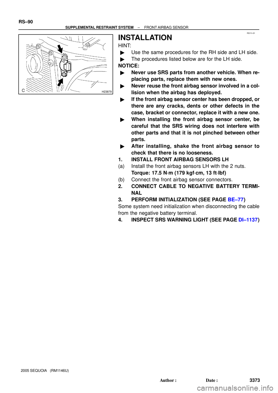
1. INSTALL FRONT AIRBAG SENSORS LH
(a) Install the front airbag sensors LH with the 2 nuts.
Torque: 17.5 N´m (179 kgf´cm, 13 ft´lbf)
(b) Connect the front airbag sensor connectors.
2. CONNECT CABLE TO NEGATIVE BATTERY TERMI-
NAL
3. PERFORM INITIALIZATION (SEE PAGE BE±77)
Some system need initialization when disconnecting the cable
from the negative battery terminal.
4. INSPECT SRS WARNING LIGHT (SEE PAGE DI±1137)
Page 3386 of 4323
RS11N±01
H20066
± SUPPLEMENTAL RESTRAINT SYSTEMSIDE AIRBAG SENSOR ASSEMBLY
RS±95
3378 Author�: Date�:
2005 SEQUOIA (RM1146U)
INSTALLATION
HINT:
�Use the same procedures for the RH side and LH side.
�The procedures listed below are for the LH side.
NOTICE:
�Never use SRS parts from another vehicle. When re-
placing parts, replace them with new ones.
�Never reuse the side airbag sensor assembly in-
volved in a collision when the airbag has deployed.
�If the side airbag sensor assembly center has been
dropped, or there are any cracks, dents or other de-
fects in the case, bracket or connector, replace it with
a new one.
�When installing the side airbag sensor assembly, be
careful that the SRS wiring does not interfere with
other parts and that it is not pinched between other
parts.
�After installing, shake the side airbag sensor assem-
bly to check that there is no looseness.
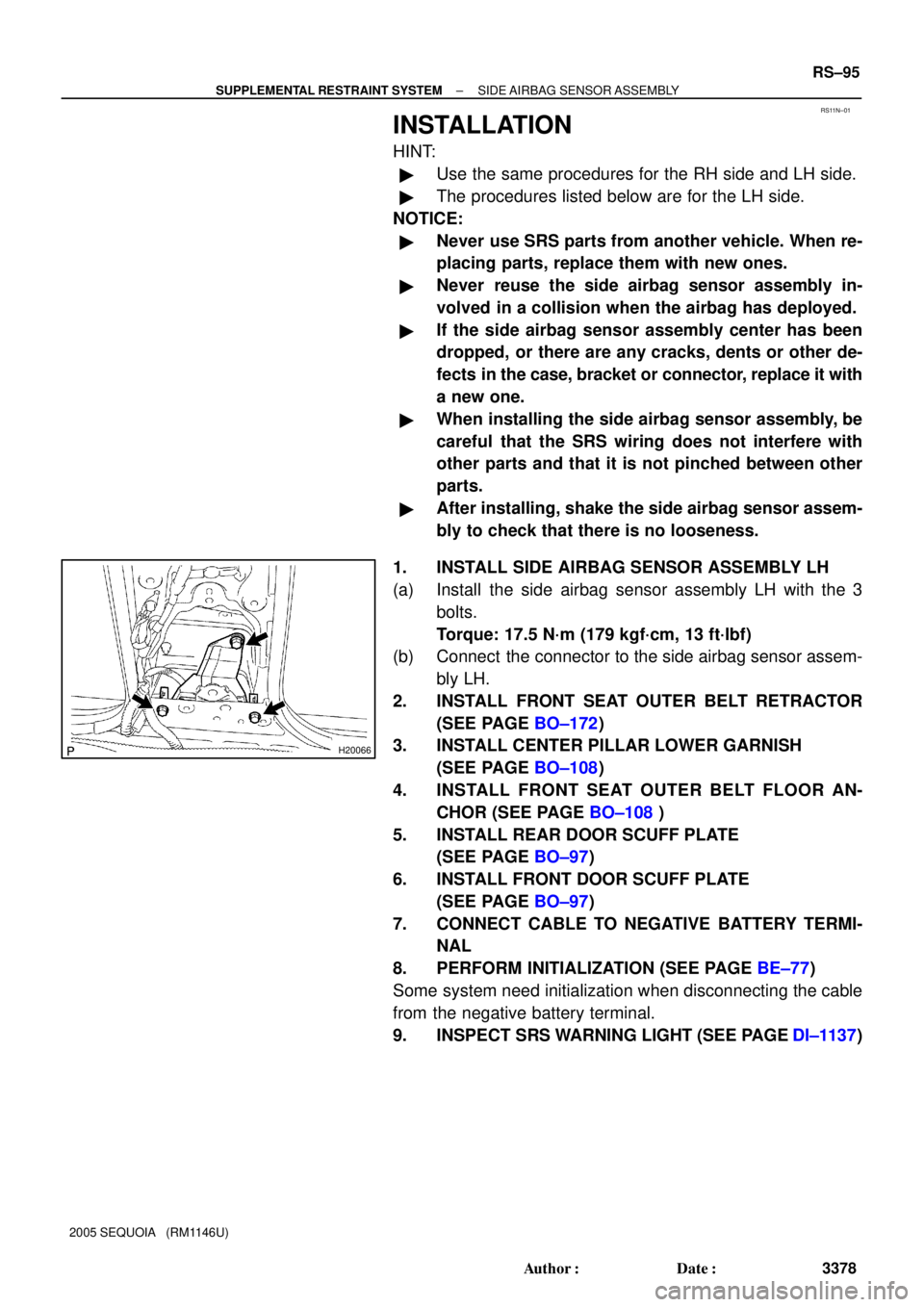
1. INSTALL SIDE AIRBAG SENSOR ASSEMBLY LH
(a) Install the side airbag sensor assembly LH with the 3
bolts.
Torque: 17.5 N´m (179 kgf´cm, 13 ft´lbf)
(b) Connect the connector to the side airbag sensor assem-
bly LH.
2. INSTALL FRONT SEAT OUTER BELT RETRACTOR
(SEE PAGE BO±172)
3. INSTALL CENTER PILLAR LOWER GARNISH
(SEE PAGE BO±108)
4. INSTALL FRONT SEAT OUTER BELT FLOOR AN-
CHOR (SEE PAGE BO±108 )
5. INSTALL REAR DOOR SCUFF PLATE
(SEE PAGE BO±97)
6. INSTALL FRONT DOOR SCUFF PLATE
(SEE PAGE BO±97)
7. CONNECT CABLE TO NEGATIVE BATTERY TERMI-
NAL
8. PERFORM INITIALIZATION (SEE PAGE BE±77)
Some system need initialization when disconnecting the cable
from the negative battery terminal.
9. INSPECT SRS WARNING LIGHT (SEE PAGE DI±1137)
Page 3391 of 4323

RS11S±01
H23905
RS±100
± SUPPLEMENTAL RESTRAINT SYSTEMCURTAIN SHIELD AIRBAG SENSOR ASSEMBLY
3383 Author�: Date�:
2005 SEQUOIA (RM1146U)
INSTALLATION
HINT:
�Use the same procedures for the RH side and LH side.
�The procedures listed below are for the LH side.
NOTICE:
�Never use SRS parts from another vehicle. When re-
placing parts, replace them with new ones.
�Never reuse the curtain shield airbag sensor assem-
bly involved in a collision when the airbag has
deployed.
�If the curtain shield airbag sensor assembly center
has been dropped, or there are any cracks, dents or
other defects in the case, bracket or connector, re-
place it with a new one.
�When installing the curtain shield airbag sensor as-
sembly center, be careful that the SRS wiring does
not interfere with other parts and that it is not pinched
between other parts.
�After installing, shake the curtain shield airbag sen-
sor assembly to check that there is no looseness.
1. INSTALL CURTAIN SHIELD AIRBAG SENSOR AS-
SEMBLY LH
(a) Install the curtain shield airbag sensor assembly LH with
the 2 nuts.
Torque:17.5 N´m (179 kgf´cm, 13 ft´lbf)
(b) Connect the curtain shield airbag sensor assembly LH
connector.
2. INSTALL RETRACTOR OF FRONT SEAT OUTER BELT
3. INSTALL QUARTER TRIM PLATE
(SEE PAGE BO±108)
4. INSTALL REAR FLOOR PANEL SUPPORT PLATE
(SEE PAGE BO±108)
5. INSTALL REAR DOOR SCUFF PLATE
(SEE PAGE BO±108)
6. INSTALL REAR SEAT NO. 2 ASSEMBLY
(SEE PAGE BO±158)
7. CONNECT CABLE TO NEGATIVE BATTERY TERMI-
NAL
Page 3399 of 4323

RS0UY±05
H24698
Seat Position
Sensor
Assembly
Seat RailFeeler
Gauge Seat Position Sensor
Assembly Protector
1 mm
(0.039 in.)
RS±108
± SUPPLEMENTAL RESTRAINT SYSTEMSEAT POSITION SENSOR ASSEMBLY
3391 Author�: Date�:
2005 SEQUOIA (RM1146U)
INSTALLATION
NOTICE:
�Never use SRS parts from another vehicle. When re-
placing parts, replace them with new ones.
�Never reuse the seat position sensor assembly in-
volved in a collision when the airbag has deployed.
�If the seat position sensor assembly center has been
dropped, or there are any cracks, dents or other de-
fects in the case, bracket or connector, replace it with
a new one.
�When installing the seat position sensor assembly
center, be careful that the SRS wiring does not inter-
fere with other parts and that it is not pinched be-
tween other parts.
�After installing, shake the seat position sensor as-
sembly to check that there is no looseness.
1. INSTALL SEAT POSITION SENSOR ASSEMBLY
(a) Using a feeler gauge 1 mm (0.039 in.), install the seat
position sensor assembly.
HINT:
Be sure that a clearance between the seat position sensor as-
sembly and the seat rail is between 0.6 mm (0.023 in.) and 2 mm
(0.079 in.).
(b) Using a torx
) socket wrench, tighten the torx) screw to
install the seat position sensor assembly.
Torque: 8.0 N´m (82 kgf´cm, 71 in.´lbf)
(c) Make sure that a clearance between the seat position
sensor assembly and the seat rail is between 0.6 mm
(0.023 in.) and 2 mm (0.079 in.).
(d) Connect the connector to the seat position sensor assem-
bly.
2. INSTALL SEAT POSITION SENSOR ASSEMBLY PRO-
TECTOR
Install the seat position sensor assembly protector to the seat
position sensor assembly.
3. Separate type (Power adjuster):
INSTALL SEAT CUSHION LOWER SHIELD, SEAT
CUSHION OUTER SHIELD AND SEAT CUSHION IN-
NER SHIELD (SEE PAGE BO±117)
4. Separate type (Power adjuster):
INSTALL SLIDE KNOB AND RECLINING KNOB
(SEE PAGE BO±117)
5. Separate type (Power adjuster):
INSTALL FRONT SEAT ASSEMBLY LH
(SEE PAGE BO±123)
Page 3405 of 4323
RS0UY±06
H23939
RS±114
± SUPPLEMENTAL RESTRAINT SYSTEMOCCUPANT CLASSIFICATION ECU
3397 Author�: Date�:
2005 SEQUOIA (RM1146U)
INSTALLATION
NOTICE:
�Never use SRS parts from another vehicle. When re-
placing parts, replace them with new ones.
�Never reuse the occupant classification ECU in-
volved in a collision when the airbag has deployed.
�If the occupant classification ECU center has been
dropped, or there are any cracks, dents or other de-
fects in the case, bracket or connector, replace it with
a new one.
�When installing the seat position sensor assembly
center, be careful that the SRS wiring does not inter-
fere with other parts and that it is not pinched be-
tween other parts.
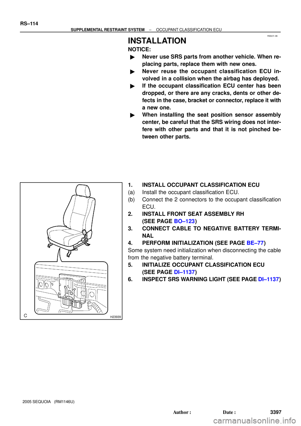
1. INSTALL OCCUPANT CLASSIFICATION ECU
(a) Install the occupant classification ECU.
(b) Connect the 2 connectors to the occupant classification
ECU.
2. INSTALL FRONT SEAT ASSEMBLY RH
(SEE PAGE BO±123)
3. CONNECT CABLE TO NEGATIVE BATTERY TERMI-
NAL
4. PERFORM INITIALIZATION (SEE PAGE BE±77)
Some system need initialization when disconnecting the cable
from the negative battery terminal.
5. INITIALIZE OCCUPANT CLASSIFICATION ECU
(SEE PAGE DI±1137)
6. INSPECT SRS WARNING LIGHT (SEE PAGE DI±1137)
Page 3426 of 4323
BE2DG±03
I28397
Engine Room R/B No. 2
Engine Room J/B
� FL Block
Instrument Panel J/B
Driver Side R/BEngine Room R/B No. 3 FL Block:
A
B
B
A
B
Engine Room R/B
No. 4
NOTICE:
When removing the FL block, pinch ºAº using pliers and pull it out.
Since ºBº is easy to damage, do not pinch with pliers. BE±14
± BODY ELECTRICALPOWER SOURCE
3418 Author�: Date�:
2005 SEQUOIA (RM1146U)
POWER SOURCE
LOCATION
Page 3429 of 4323
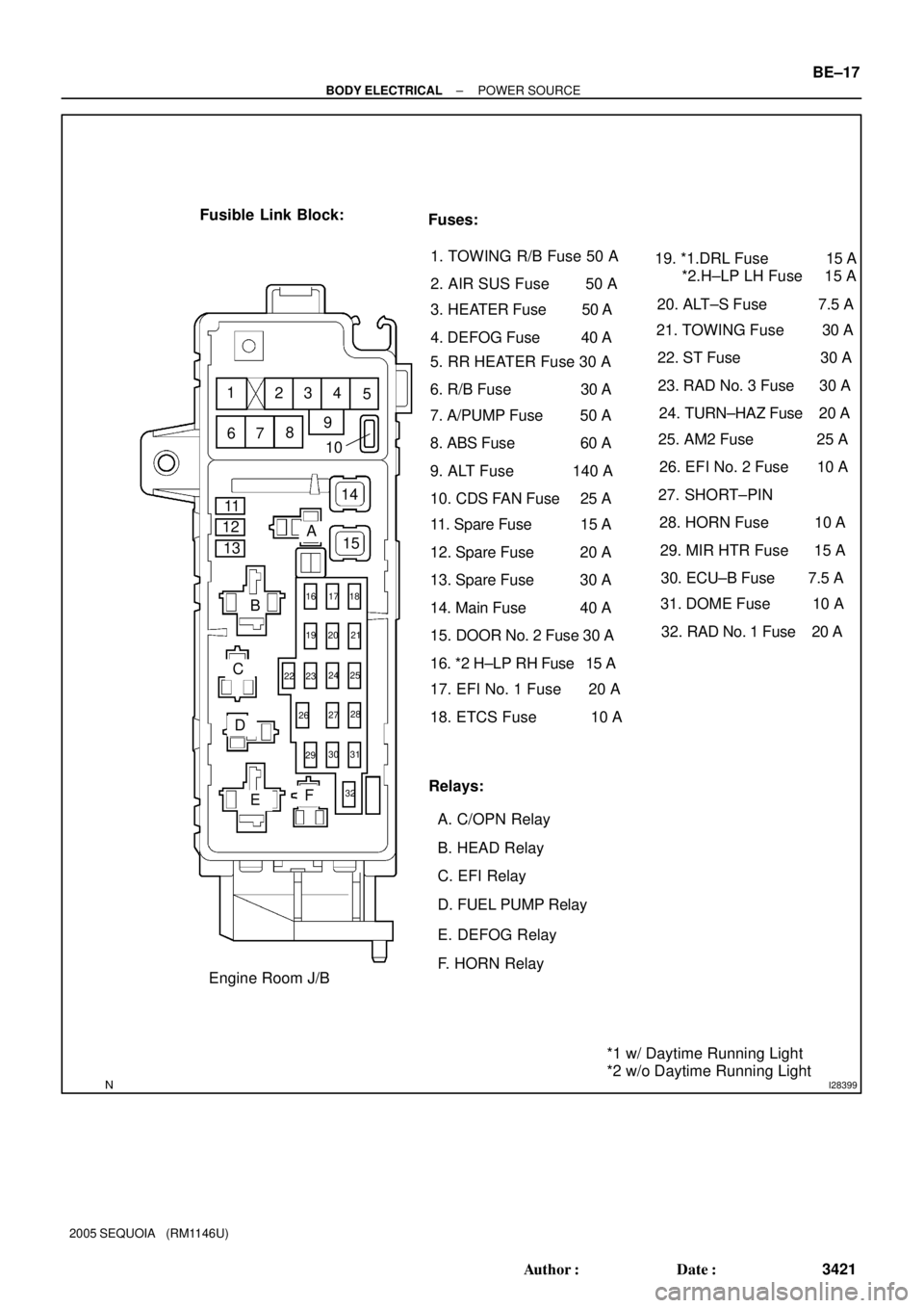
I28399
Fusible Link Block:
Relays: Fuses:
5. RR HEATER Fuse 30 A
A. C/OPN Relay
B. HEAD Relay
C. EFI Relay
D. FUEL PUMP Relay
E. DEFOG Relay
F. HORN Relay
Engine Room J/B6. R/B Fuse 30 A
7. A/PUMP Fuse 50 A
8. ABS Fuse 60 A
9. ALT Fuse 140 A
10. CDS FAN Fuse 25 A
11. Spare Fuse 15 A
12. Spare Fuse 20 A
13. Spare Fuse 30 A
14. Main Fuse 40 A
15. DOOR No. 2 Fuse 30 A
16. *2 H±LP RH Fuse 15 A
17. EFI No. 1 Fuse 20 A
18. ETCS Fuse 10 A19. *1.DRL Fuse 15 A
*2.H±LP LH Fuse 15 A
20. ALT±S Fuse 7.5 A
21. TOWING Fuse 30 A
22. ST Fuse 30 A
23. RAD No. 3 Fuse 30 A
24. TURN±HAZ Fuse 20 A
25. AM2 Fuse 25 A
26. EFI No. 2 Fuse 10 A
27. SHORT±PIN
28. HORN Fuse 10 A
29. MIR HTR Fuse 15 A
30. ECU±B Fuse 7.5 A
31. DOME Fuse 10 A
32. RAD No. 1 Fuse 20 A
*1 w/ Daytime Running Light
*2 w/o Daytime Running Light 15
16 17 18
19 20 21
262728
2930
A
B
C
D
EF 1
234
5
6789
10
22 2324 25
31
32
11
12
13141. TOWING R/B Fuse 50 A
2. AIR SUS Fuse 50 A
3. HEATER Fuse 50 A
4. DEFOG Fuse 40 A
± BODY ELECTRICALPOWER SOURCE
BE±17
3421 Author�: Date�:
2005 SEQUOIA (RM1146U)