Page 3341 of 4323

RS11B±01
AB0152
SST RS±50
± SUPPLEMENTAL RESTRAINT SYSTEMSIDE AIRBAG ASSEMBLY (Power Adjuster Type)
3333 Author�: Date�:
2005 SEQUOIA (RM1146U)
DISPOSAL
HINT:
�Use the same procedures for the RH side and LH side.
�The procedures listed below are for the LH side.
�When scrapping a vehicle equipped with the SRS or dis-
posing of the front seat airbag assembly LH, be sure to
deploy the airbag first in accordance with the procedure
described below. If any abnormality occurs with the airbag
deployment, contact the SERVICE DEPT. of TOYOTA
MOTOR SALES, U.S.A., INC.
CAUTION:
�Never dispose of a front seat airbag assembly that
has an undeployed airbag.
�The airbag produces an exploding sound when it is
deployed, so perform the operation outdoors and
where it will not create a nuisance to nearby resi-
dents.
�When deploying the airbag, always use the specified
SST (SRS Airbag Deployment Tool). Perform the op-
eration in a place away from electrical noise.
�When deploying the airbag, perform the operation at
least 10 m (33 ft) away from the front seat airbag as-
sembly.
�The front seat airbag assembly becomes extremely
hot when the airbag is deployed, so do not touch it for
at least 30 minutes after deployment.
�Use gloves and safety glasses when handling a front
seat airbag assembly with a deployed airbag.
�Always wash your hands with water after completing
the operation.
�Do not apply water, etc. to a front seat airbag assem-
bly with a deployed airbag.
HINT:
Prepare a battery as the power source to deploy the airbag.
Page 3342 of 4323

AB0158
Battery
SST
H17490
H17494SST SST
R13455
10 m (33 ft) or more
SSTBattery
± SUPPLEMENTAL RESTRAINT SYSTEMSIDE AIRBAG ASSEMBLY (Power Adjuster Type)
RS±51
3334 Author�: Date�:
2005 SEQUOIA (RM1146U)
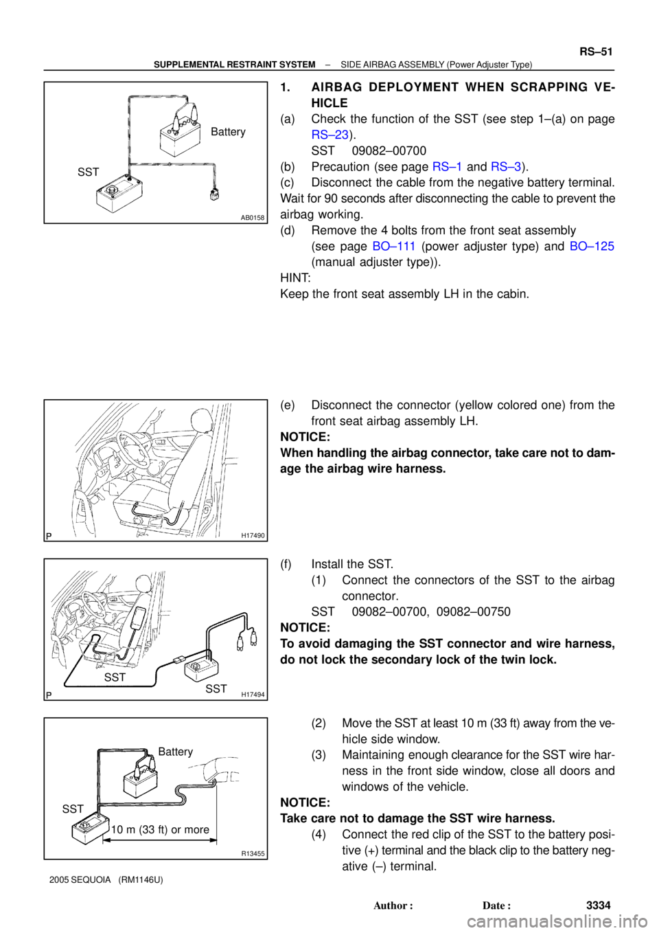
1. AIRBAG DEPLOYMENT WHEN SCRAPPING VE-
HICLE
(a) Check the function of the SST (see step 1±(a) on page
RS±23).
SST 09082±00700
(b) Precaution (see page RS±1 and RS±3).
(c) Disconnect the cable from the negative battery terminal.
Wait for 90 seconds after disconnecting the cable to prevent the
airbag working.
(d) Remove the 4 bolts from the front seat assembly
(see page BO±111 (power adjuster type) and BO±125
(manual adjuster type)).
HINT:
Keep the front seat assembly LH in the cabin.
(e) Disconnect the connector (yellow colored one) from the
front seat airbag assembly LH.
NOTICE:
When handling the airbag connector, take care not to dam-
age the airbag wire harness.
(f) Install the SST.
(1) Connect the connectors of the SST to the airbag
connector.
SST 09082±00700, 09082±00750
NOTICE:
To avoid damaging the SST connector and wire harness,
do not lock the secondary lock of the twin lock.
(2) Move the SST at least 10 m (33 ft) away from the ve-
hicle side window.
(3) Maintaining enough clearance for the SST wire har-
ness in the front side window, close all doors and
windows of the vehicle.
NOTICE:
Take care not to damage the SST wire harness.
(4) Connect the red clip of the SST to the battery posi-
tive (+) terminal and the black clip to the battery neg-
ative (±) terminal.
Page 3348 of 4323

RS11C±01
H24319
H24318Hog Ring
H24321Hog Ring
± SUPPLEMENTAL RESTRAINT SYSTEMSIDE AIRBAG ASSEMBLY (Power Adjuster Type)
RS±57
3340 Author�: Date�:
2005 SEQUOIA (RM1146U)
INSTALLATION
HINT:
�Use the same procedures for the RH side and LH side.
�The procedures listed below are for the LH side.
NOTICE:
�If the side airbag assembly has been dropped, or
there are cracks, dents or other defects in the case or
connector, replace the side airbag assembly with a
new one.
�When installing the side airbag assembly, take care
it is not pinched between other parts.
�Never use airbag parts from another vehicle. When
replacing parts, replace them with new ones.
1. INSTALL SEATBACK COVER
(a) Install the seatback cover to the seatback pad.
(b) Install the 2 headrest supports.
(c) Turn up the seatback cover and install the hog rings.
2. INSTALL SEATBACK COVER AND PAD
(a) Install the seatback cover and pad to the seat frame as-
sembly.
(b) Install the 2 headrest supports to the seat frame assem-
bly.
(c) Install the hog rings to the seat frame assembly.
(d) Install the hog rings to the seat frame assembly.
Page 3355 of 4323

RS0LH±05
H16230
Cross Section
H23933
RS±64
± SUPPLEMENTAL RESTRAINT SYSTEMSIDE AIRBAG ASSEMBLY (Manual Adjuster Type)
3347 Author�: Date�:
2005 SEQUOIA (RM1146U)
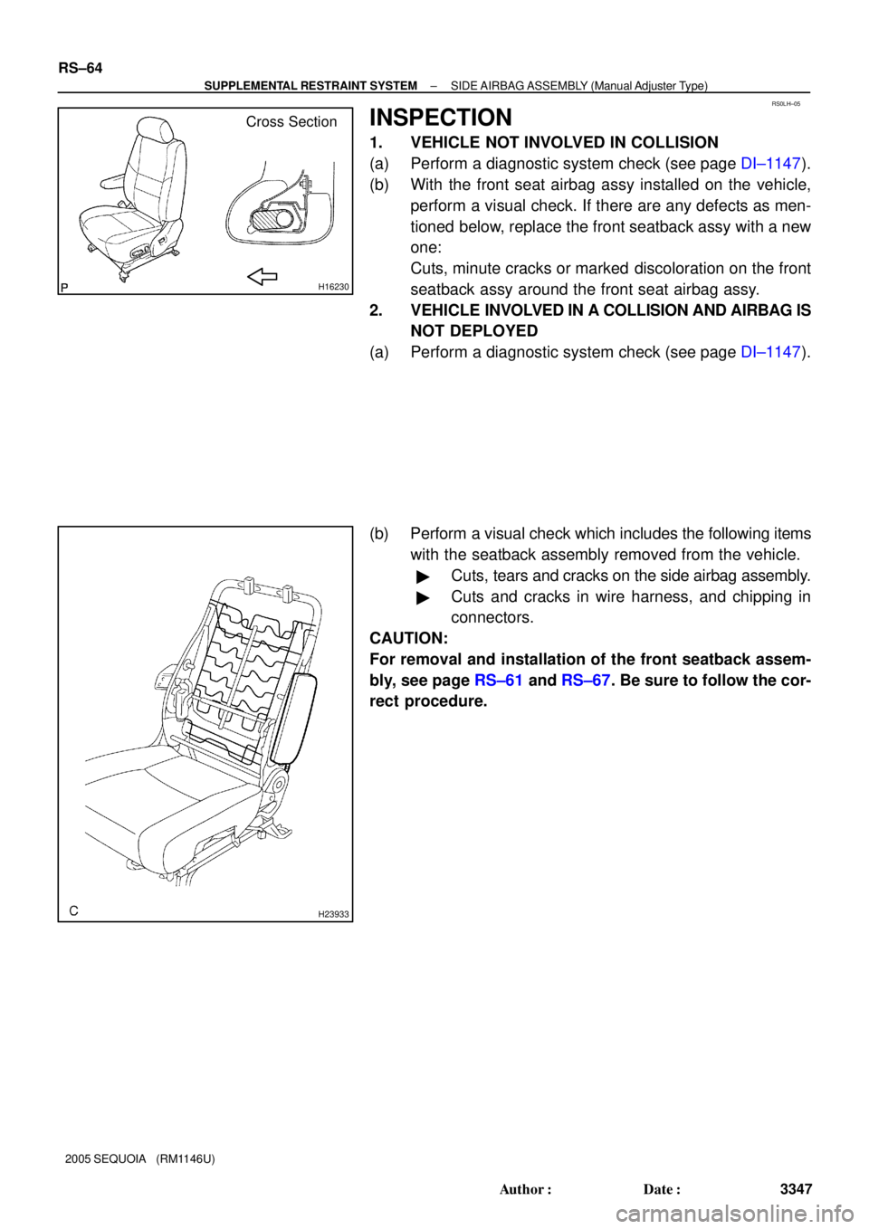
INSPECTION
1. VEHICLE NOT INVOLVED IN COLLISION
(a) Perform a diagnostic system check (see page DI±1147).
(b) With the front seat airbag assy installed on the vehicle,
perform a visual check. If there are any defects as men-
tioned below, replace the front seatback assy with a new
one:
Cuts, minute cracks or marked discoloration on the front
seatback assy around the front seat airbag assy.
2. VEHICLE INVOLVED IN A COLLISION AND AIRBAG IS
NOT DEPLOYED
(a) Perform a diagnostic system check (see page DI±1147).
(b) Perform a visual check which includes the following items
with the seatback assembly removed from the vehicle.
�Cuts, tears and cracks on the side airbag assembly.
�Cuts and cracks in wire harness, and chipping in
connectors.
CAUTION:
For removal and installation of the front seatback assem-
bly, see page RS±61 and RS±67. Be sure to follow the cor-
rect procedure.
Page 3358 of 4323

RS11E±01
H24319
H24339
H24338Hog Ring
± SUPPLEMENTAL RESTRAINT SYSTEMSIDE AIRBAG ASSEMBLY (Manual Adjuster Type)
RS±67
3350 Author�: Date�:
2005 SEQUOIA (RM1146U)
INSTALLATION
HINT:
�Use the same procedures for the RH side and LH side.
�The procedures listed below are for the LH side.
NOTICE:
�If the side airbag assembly has been dropped, or
there are cracks, dents or other defects in the case or
connector, replace the side airbag assembly with a
new one.
�When installing the side airbag assembly, take care
it is not pinched between other parts.
�Never use airbag parts from another vehicle. When
replacing parts, replace them with new ones.
1. INSTALL SEATBACK COVER
(a) Install the seatback cover to the seatback pad.
(b) Install the 2 headrest supports.
(c) Turn up the seatback cover and install the hog rings.
2. INSTALL SEATBACK COVER AND PAD
(a) Install the seatback cover and pad to the seat frame as-
sembly.
(b) Install the hog rings to the seat frame assembly.
(c) Install the hog rings to the seat frame assembly.
Page 3364 of 4323

RS11G±01
AB0152
SST
± SUPPLEMENTAL RESTRAINT SYSTEMCURTAIN SHIELD AIRBAG ASSEMBLY
RS±73
3356 Author�: Date�:
2005 SEQUOIA (RM1146U)
DISPOSAL
HINT:
�Use the same procedures for the RH side and LH side.
�The procedures listed below are for the LH side.
�When scrapping a vehicle equipped with the SRS or dis-
posing of the curtain shield airbag assembly, be sure to
deploy the airbag first in accordance with the procedure
described below. If any abnormality occurs with the airbag
deployment, contact the TOYOTA MOTOR SALES,
U.S.A., INC.
CAUTION:
�Never dispose of a curtain shield airbag assembly
which has an undeployed airbag.
�The airbag produces an exploding sound when it is
deployed, so perform the operation outdoors and
where it will not create a nuisance to nearby resi-
dents.
�When deploying the airbag, always use the specified
SST (SRS Airbag Deployment Tool). Perform the op-
eration in a place away from electrical noise.
�When deploying the airbag, perform the operation at
least 10 m (33 ft) away from the curtain shield airbag
assembly.
�The curtain shield airbag assembly becomes ex-
tremely hot when the airbag is deployed, so do not
touch it for at least 30 minutes after deployment.
�Use gloves and safety glasses when handling a cur-
tain shield airbag assembly with a deployed airbag.
�Do not apply water, etc. to a front passenger airbag
assembly with a deployed airbag.
�Always wash your hands with water after completing
the operation.
HINT:
Prepare a battery as the power source to deploy the airbag.
Page 3365 of 4323

AB0158
Battery
SST
H23899
SST
R13455
10 m (33 ft) or more
SSTBattery RS±74
± SUPPLEMENTAL RESTRAINT SYSTEMCURTAIN SHIELD AIRBAG ASSEMBLY
3357 Author�: Date�:
2005 SEQUOIA (RM1146U)
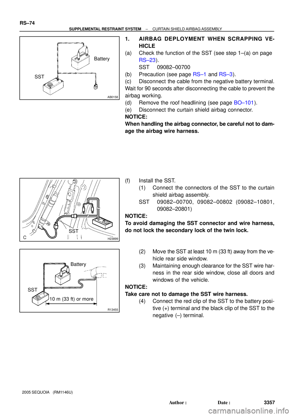
1. AIRBAG DEPLOYMENT WHEN SCRAPPING VE-
HICLE
(a) Check the function of the SST (see step 1±(a) on page
RS±23).
SST 09082±00700
(b) Precaution (see page RS±1 and RS±3).
(c) Disconnect the cable from the negative battery terminal.
Wait for 90 seconds after disconnecting the cable to prevent the
airbag working.
(d) Remove the roof headlining (see page BO±101).
(e) Disconnect the curtain shield airbag connector.
NOTICE:
When handling the airbag connector, be careful not to dam-
age the airbag wire harness.
(f) Install the SST.
(1) Connect the connectors of the SST to the curtain
shield airbag assembly.
SST 09082±00700, 09082±00802 (09082±10801,
09082±20801)
NOTICE:
To avoid damaging the SST connector and wire harness,
do not lock the secondary lock of the twin lock.
(2) Move the SST at least 10 m (33 ft) away from the ve-
hicle rear side window.
(3) Maintaining enough clearance for the SST wire har-
ness in the rear side window, close all doors and
windows of the vehicle.
NOTICE:
Take care not to damage the SST wire harness.
(4) Connect the red clip of the SST to the battery posi-
tive (+) terminal and the black clip of the SST to the
negative (±) terminal.
Page 3371 of 4323

RS0TH±07
H23897
RS±80
± SUPPLEMENTAL RESTRAINT SYSTEMCURTAIN SHIELD AIRBAG ASSEMBLY
3363 Author�: Date�:
2005 SEQUOIA (RM1146U)
INSTALLATION
HINT:
�Use the same procedures for the RH side and LH side.
�The procedures listed below are for the LH side.
1. INSTALL CURTAIN SHIELD AIRBAG ASSEMBLY
(a) Install the curtain shield airbag assembly with the 13
bolts.
Torque: 9.8 N´m (100 kgf´cm, 7 ft´lbf)
CAUTION:
Pay attention not to twist the deployment section of the cur-
tain shield airbag assembly.
NOTICE:
�If the curtain shield airbag assembly has been
dropped, or there are cracks, dents or other defects
in the case or connector, replace the curtain shield
airbag assembly with a new one.
�When installing the curtain shield airbag assembly,
take care it is not pinched between other parts.
�Never use airbag parts from another vehicle. When
replacing parts, replace them with new ones.
(b) Connect the connector of the curtain shield airbag as-
sembly.
2. INSTALL ROOF HEADLINING (SEE PAGE BO±108)
3. CONNECT CABLE TO NEGATIVE BATTERY TERMI-
NAL
4. PERFORM INITIALIZATION (SEE PAGE BE±77)
Some system need initialization when disconnecting the cable
from the negative battery terminal.
5. INSPECT SRS WARNING LIGHT (SEE PAGE DI±1137)