Page 1132 of 4323

5 Check speed sensor an")
W04200
Normal Signal Waveform
1 V / Division2 m/s / DivisionGND
R07880
DI±930
± DIAGNOSTICSABS WITH EBD & BA & TRAC & VSC SYSTEM
1124 Author�: Date�:
2005 SEQUOIA (RM1146U)
5 Check speed sensor and sensor rotor serrations.
INSPECTION USING OSCILLOSCOPE
PREPARATION:
Connect the oscilloscope to the terminal FR+ ± FR±, FL+ ± FL±,
RR+ ± RR± and RL+ ± RL± of the skid control ECU.
CHECK:
Drive the vehicle at about 12 mph (20 km/h), and check the sig-
nal waveform.
OK:
A waveform as shown in the figure should be output.
HINT:
�As the vehicle speed (wheel revolution speed) increases,
a cycle of the waveform becomes shorter and the fluctua-
tion in the output voltage becomes greater.
�When noise is identified in the waveform on the oscillo-
scope, error signals are generated due to the speed sen-
sor rotor's scratches, looseness or foreign matter depos-
ited on it.
OK Replace skid control ECU
(See page BR±52).
NOTICE:
When replacing the skid control ECU, perform the zero
point calibration (See page DI±897).
NG
6 Check sensor rotor and sensor tip.
Front:
PREPARATION:
Remove the disc (See page SA±22).
CHECK:
Check the sensor rotor serrations.
OK:
No scratches, missing teeth or foreign objects.
PREPARATION:
Remove the front speed sensor (See page BR±56).
CHECK:
Check the sensor tip.
OK:
No scratches or foreign objects on the sensor tip.
HINT:
Remove any foreign matter if identified.
Check the output waveform again after reassembly.
Page 1137 of 4323
F16988
GND
+BM
+BS
± DIAGNOSTICSABS WITH EBD & BA & TRAC & VSC SYSTEM
DI±935
1129 Author�: Date�:
2005 SEQUOIA (RM1146U)
INSPECTION PROCEDURE
1 Check voltage between terminals +BS, +BM and GND of the skid control ECU
connector.
PREPARATION:
Disconnect the skid control ECU connector.
CHECK:
Measure the voltage between terminals +BS, +BM and GND of
the skid control ECU harness side connector.
OK:
Voltage: 10 to 14 V
NG Check and replace ABS fuses.
Check and repair harness or connector.
OK
If the same code is still indicated after the DTC is deleted, check the condition of each connection.
If the connections are normal, the skid control ECU may be defective.
NOTICE:
When replacing the skid control ECU, perform the zero point calibration (See page DI±897).
Page 1139 of 4323
± DIAGNOSTICSABS WITH EBD & BA & TRAC & VSC SYSTEM
DI±937
1131 Author�: Date�:
2005 SEQUOIA (RM1146U)
DTC C1202 / 52 Brake Fluid Warning Switch Circuit
CIRCUIT DESCRIPTION
The brake fluid level warning switch sends the appropriate signal to the skid control ECU when the brake
fluid level drops.
A brake fluid level signal is transmitted from the translate ECU to the skid control ECU.
DTC No.DTC Detecting ConditionTrouble Area
C1202 / 52
When any of the following conditions are detected:
1. Low fluid level condition in the brake master cylinder
reservoir tank continues for 30 sec. or more when ve-
hicle stops, or for 60 sec. or more when driving.
2. With ECU terminal IG1 voltage is 9.5 V to 17.2 V and
open circuit for the brake fluid level warning switch cir-
cuit continues for 2 sec. or more.�Brake fluid level
�Brake fluid level warning switch
�Brake fluid level warning switch circuit
�Skid control ECU
�CAN1 communication system
�Translate ECU
DIDM7±01
Page 1148 of 4323
DI±946
± DIAGNOSTICSABS WITH EBD & BA & TRAC & VSC SYSTEM
1140 Author�: Date�:
2005 SEQUOIA (RM1146U)
DTCC1231 / 31, C1335 / 35Steering Angle Sensor Circuit
CIRCUIT DESCRIPTION
The steering angle sensor signal is sent to the skid control ECU via the CAN communication system. When
there is a malfunction in the communication system, the DTCs will be detected by the diagnosis function.
DTC No.DTC Detecting ConditionTrouble Area
C1231 / 31Data is not transmitted to the steering angle sensor for a
fixed time invalid steering angle sensor data.
�Translate ECU
�Steering angle sensor
�Steering angle sensor communication circuit
�Skid control ECU
�CAN communication system
C1335 / 35
When the +BS terminal voltage is 9.5 V or more, data trans-
mission from the steering angle sensor is impossible for 1
sec. or more.
�Translate ECU
�Steering angle sensor
�Steering angle sensor to translate ECU circuit
�Skid control ECU
�CAN1 communication system
DI93L±04
Page 1155 of 4323
F19145
Yaw Rate (Decel-
eration) Sensor
VYS
GYAW
± DIAGNOSTICSABS WITH EBD & BA & TRAC & VSC SYSTEM
DI±953
1147 Author�: Date�:
2005 SEQUOIA (RM1146U)
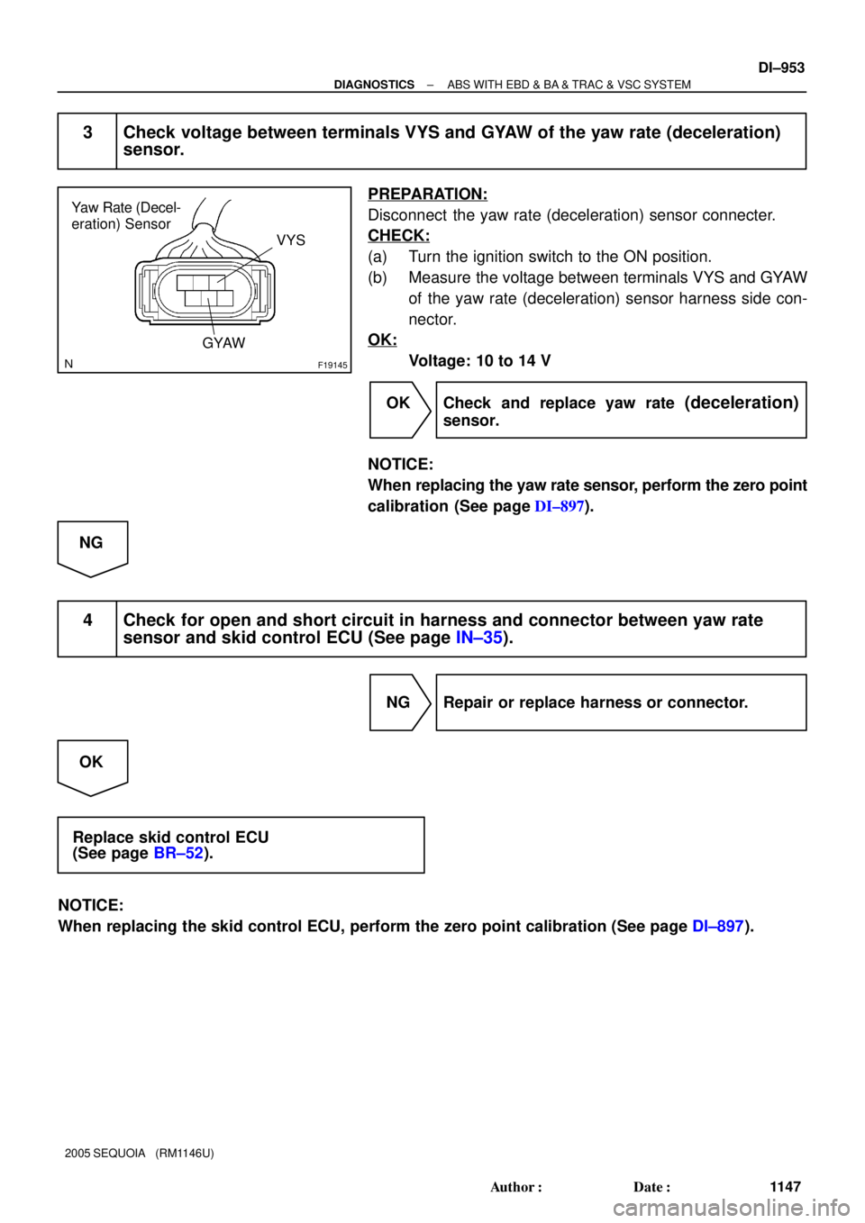
3 Check voltage between terminals VYS and GYAW of the yaw rate (deceleration)
sensor.
PREPARATION:
Disconnect the yaw rate (deceleration) sensor connecter.
CHECK:
(a) Turn the ignition switch to the ON position.
(b) Measure the voltage between terminals VYS and GYAW
of the yaw rate (deceleration) sensor harness side con-
nector.
OK:
Voltage: 10 to 14 V
OK Check and replace yaw rate
(deceleration)
sensor.
NOTICE:
When replacing the yaw rate sensor, perform the zero point
calibration (See page DI±897).
NG
4 Check for open and short circuit in harness and connector between yaw rate
sensor and skid control ECU (See page IN±35).
NG Repair or replace harness or connector.
OK
Replace skid control ECU
(See page BR±52).
NOTICE:
When replacing the skid control ECU, perform the zero point calibration (See page DI±897).
Page 1158 of 4323
F19145
Yaw Rate Sensor
VYS
GYAW
DI±956
± DIAGNOSTICSABS WITH EBD & BA & TRAC & VSC SYSTEM
1150 Author�: Date�:
2005 SEQUOIA (RM1146U)
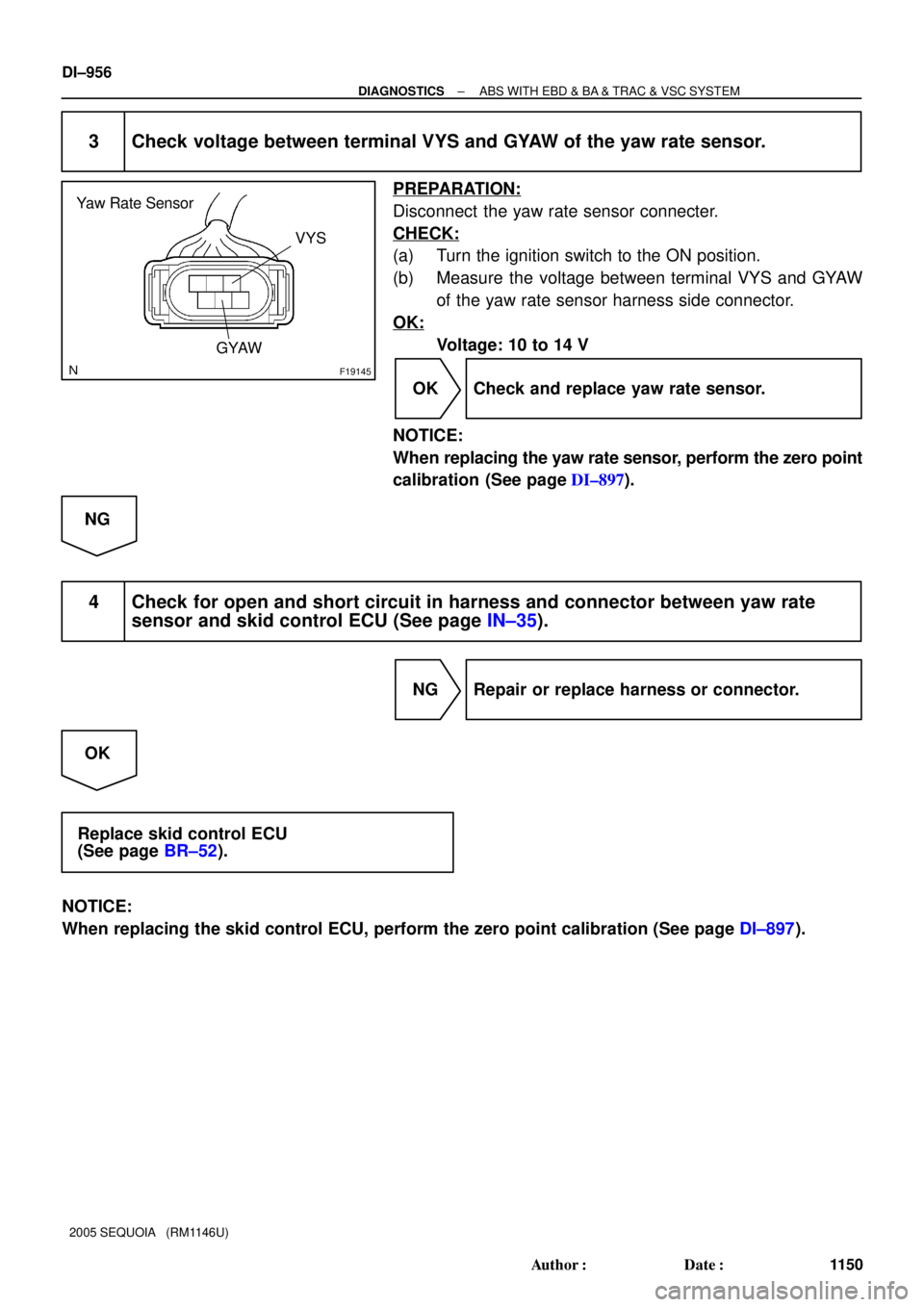
3 Check voltage between terminal VYS and GYAW of the yaw rate sensor.
PREPARATION:
Disconnect the yaw rate sensor connecter.
CHECK:
(a) Turn the ignition switch to the ON position.
(b) Measure the voltage between terminal VYS and GYAW
of the yaw rate sensor harness side connector.
OK:
Voltage: 10 to 14 V
OK Check and replace yaw rate sensor.
NOTICE:
When replacing the yaw rate sensor, perform the zero point
calibration (See page DI±897).
NG
4 Check for open and short circuit in harness and connector between yaw rate
sensor and skid control ECU (See page IN±35).
NG Repair or replace harness or connector.
OK
Replace skid control ECU
(See page BR±52).
NOTICE:
When replacing the skid control ECU, perform the zero point calibration (See page DI±897).
Page 1159 of 4323
F19782
Battery16
S1+BS
GND1
GND2
+BM S1
S1 S1 47
1
32 B±R
B±R
W±B
W±B W±B W±B 5 BF10
Fusible Link BlockABS & VSC Actuator
(Skid Control ECU)
IG J18
J/C
A A3
ABS
Motor Relay
Pump
Motor IL117
IL19
± DIAGNOSTICSABS WITH EBD & BA & TRAC & VSC SYSTEM
DI±957
1151 Author�: Date�:
2005 SEQUOIA (RM1146U)
DTC C1241 / 41 Power Source Circuit
CIRCUIT DESCRIPTION
If there is a problem with the skid control ECU power supply circuit, the skid control ECU outputs DTC and
prohibits operation under the fail safe function.
DTC No.DTC Detecting ConditionTrouble Area
C1241 / 41
When any of the following conditions are detected:
1. ECU terminal +BM/+BS voltage is too low for a fixed
time during driving.
2. ECU terminal +BM/+BS voltage is too high for a fixed
time while ignition switch is ON.�Battery
�Charging system
�Power source circuit (+BM, +BS)
�Skid control ECU
WIRING DIAGRAM
DIDMA±01
Page 1161 of 4323
F16988
GND+BM
+BS
F16991
GND
± DIAGNOSTICSABS WITH EBD & BA & TRAC & VSC SYSTEM
DI±959
1153 Author�: Date�:
2005 SEQUOIA (RM1146U)
3 Check voltage of the +BM/+BS power source.
PREPARATION:
Disconnect the skid control ECU connector.
CHECK:
Measure the voltage between terminal +BM/+BS and GND of
the skid control ECU harness side connector.
OK:
Voltage: 10 to 14 V
OK Replace skid control ECU
(See page BR±52).
NOTICE:
When replacing the skid control ECU, perform the zero
point calibration (See page DI±897).
NG
4 Check continuity between terminal GND of the skid control ECU connector and
body ground (See page IN±35).
PREPARATION:
Disconnect the skid control ECU connector.
CHECK:
Measure the resistance between terminal GND of the skid con-
trol ECU harness side connector and body ground.
OK:
Resistance: 1 W or less
NG Repair or replace harness or connector.
OK
Check for open circuit in harness and connector between skid control ECU and battery
(See page IN±35).


IG J18
J/C
A A3
ABS
Motor Relay
Pump
Motor IL117
IL19")