Page 1257 of 4323
F19788
6
IL2
7 CANL
S12
VSC+ 6
TC 28Translate ECU
CANH11
VSC±
TC
CG
J43
J/CIG 4A55
4BP±B W
L ABS & VSC Actuator
(Skid Control ECU)
7
S1T5
T5
T5 W
L
IL2
P±B D6
Data Link Connector 3
O 13
4Sub J/B No. 4
O
AA (*) CAN1 Circuit
(*)
(*)
(*) (*)
± DIAGNOSTICSABS WITH EBD & BA & TRAC & VSC SYSTEM
DI±1055
1249 Author�: Date�:
2005 SEQUOIA (RM1146U)
Tc Terminal Circuit
CIRCUIT DESCRIPTION
Connecting terminals Tc and CG of the DLC3 causes the skid control ECU to indicate the DTC by blinking
the ABS warning light, VSC TRAC warning light and BRAKE warning light.
WIRING DIAGRAM
DI94B±04
Page 1258 of 4323
F09678
ON
DLC3
Tc
CG (+)(±)
DI±1056
± DIAGNOSTICSABS WITH EBD & BA & TRAC & VSC SYSTEM
1250 Author�: Date�:
2005 SEQUOIA (RM1146U)
INSPECTION PROCEDURE
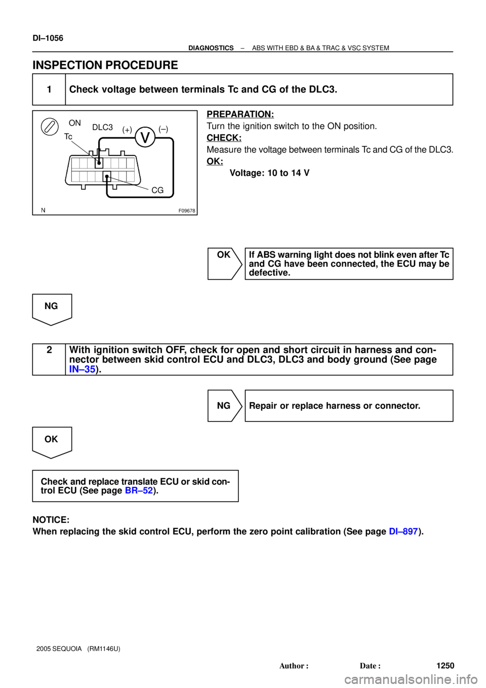
1 Check voltage between terminals Tc and CG of the DLC3.
PREPARATION:
Turn the ignition switch to the ON position.
CHECK:
Measure the voltage between terminals Tc and CG of the DLC3.
OK:
Voltage: 10 to 14 V
OK If ABS warning light does not blink even after Tc
and CG have been connected, the ECU may be
defective.
NG
2 With ignition switch OFF, check for open and short circuit in harness and con-
nector between skid control ECU and DLC3, DLC3 and body ground (See page
IN±35).
NG Repair or replace harness or connector.
OK
Check and replace translate ECU or skid con-
trol ECU (See page BR±52).
NOTICE:
When replacing the skid control ECU, perform the zero point calibration (See page DI±897).
Page 1259 of 4323
D6
DataLink
Connector
F19789
ABS & VSC Actuator
(Skid Control ECU)
R±L
T5 27
TS2440
S1
12
O
IG TS
CG
4R±LR±L
R±LTS
IL1 Translate ECU
3
O
AA J43
J/C4C 4B
4A6 66 Sub J/B No.4
(*) CAN1 Circuit (*)
± DIAGNOSTICSABS WITH EBD & BA & TRAC & VSC SYSTEM
DI±1057
1251 Author�: Date�:
2005 SEQUOIA (RM1146U)
Ts Terminal Circuit
CIRCUIT DESCRIPTION
In sensor check mode (test mode), a malfunction of the speed sensor that cannot be judged when the vehicle
is stopped is judged while driving.
Transition to sensor check mode (test mode) can be performed by connecting terminals Ts and CG of the
DLC3 and turning the ignition switch from OFF to ON.
WIRING DIAGRAM
DI94A±05
Page 1260 of 4323
F18920
DLC3
Ts
CG ON
(+) (±)
DI±1058
± DIAGNOSTICSABS WITH EBD & BA & TRAC & VSC SYSTEM
1252 Author�: Date�:
2005 SEQUOIA (RM1146U)
INSPECTION PROCEDURE
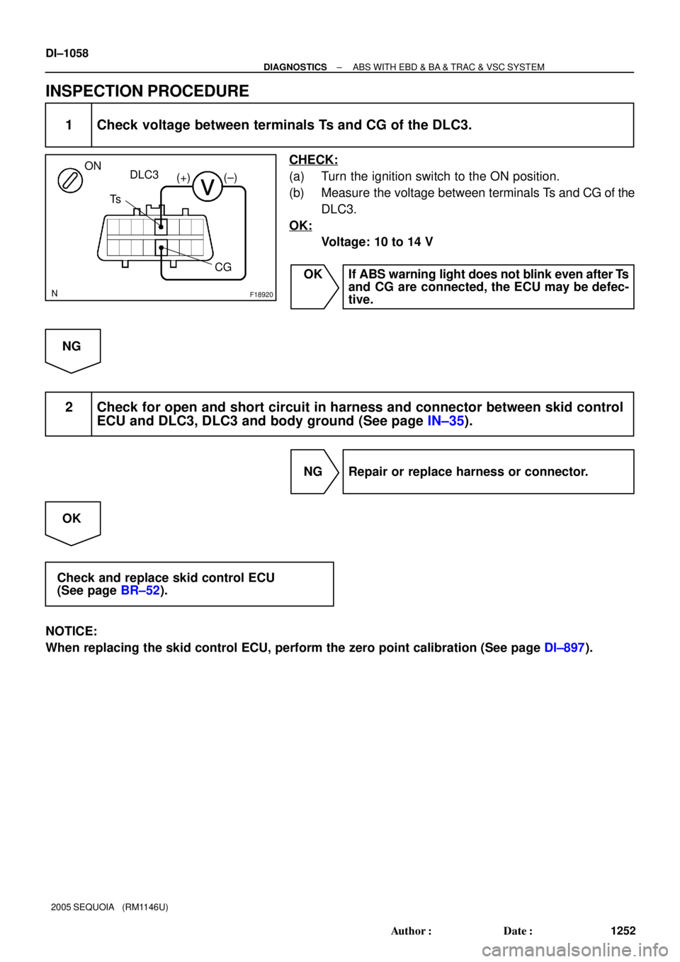
1 Check voltage between terminals Ts and CG of the DLC3.
CHECK:
(a) Turn the ignition switch to the ON position.
(b) Measure the voltage between terminals Ts and CG of the
DLC3.
OK:
Voltage: 10 to 14 V
OK If ABS warning light does not blink even after Ts
and CG are connected, the ECU may be defec-
tive.
NG
2 Check for open and short circuit in harness and connector between skid control
ECU and DLC3, DLC3 and body ground (See page IN±35).
NG Repair or replace harness or connector.
OK
Check and replace skid control ECU
(See page BR±52).
NOTICE:
When replacing the skid control ECU, perform the zero point calibration (See page DI±897).
Page 1263 of 4323
F17798
Repair Wire
± DIAGNOSTICSCAN COMMUNICATION SYSTEM
DI±1061
1255 Author�: Date�:
2005 SEQUOIA (RM1146U)
(b) If it is impossible to check continuity from the rear of the
connector, then use a repair wire to check the connector.
3. PRECAUTION FOR DISCONNECTING THE BATTERY CABLE
NOTICE:
When disconnecting the battery terminal, initialize the following system after the terminal is recon-
nected.
System NameSee Page
Back Door Power Window Control SystemBE±77
Page 1266 of 4323

SYSTEM DESCRIPTION
1. BRIEF DESCRIPTION
(a) The CAN (Controller Area Network) is a serial data c")
DIDI0±01
DI±1064
± DIAGNOSTICSCAN COMMUNICATION SYSTEM
1258 Author�: Date�:
2005 SEQUOIA (RM1146U)
SYSTEM DESCRIPTION
1. BRIEF DESCRIPTION
(a) The CAN (Controller Area Network) is a serial data communication system for real time application.
It is an in±vehicle multiplex communication system that has a high communication speed (500 kbps)
and the function to detect malfunctions.
(b) By pairing the CANH and CANL bus lines, the CAN performs communication based on differential volt-
age.
(c) Many ECUs (sensors) installed in the vehicle operate by sharing information and communicating with
each other.
(d) The CAN has two resistors of 120 W which are necessary to communicate with the main bus line.
2. DEFINITION OF TERMS
(a) Main bus line
(1) The main bus line is a wire harness between the two terminus circuits on the bus (communication
line). This is the main bus in the CAN communication system.
(b) Sub bus line
(1) The sub bus line is a wire harness that diverges from the main bus line to the ECU.
3. ECUs THAT COMMUNICATE THROUGH CAN COMMUNICATION SYSTEM
(a) Translate ECU
(b) Suspension Control ECU
(c) ECM
4. DIAGNOSTIC CODE FOR CAN COMMUNICATION SYSTEM
DTCs for the CAN communication system are as follows:
U0100/65, U0122/67, U0132/72, 65, 94.
HINT:
If C1201/51, C1202/52 or C1203/53 is output from skid control ECU, perform troubleshooting of each diag-
nosis code (see page DI±921).
5. REMARK FOR TROUBLESHOOTING
(a) Trouble in the CAN bus (communication line) can be checked from the DLC3 (except when there is
a wire break in lines other than the sub bus line of the DLC3).
NOTICE:
Do not insert the tester directly into the DLC3 connector. Be sure to use a service wire.
(b) The CAN communication system cannot detect trouble in the sub bus line of the DLC3 even though
the DLC3 is also connected to the CAN communication system.
6. HOW TO DISTINGUISH THE CAN J/C CONNECTOR
In the CAN communication system, all connectors connected to the CAN J/C are the same shape. The con-
nectors connected to the CAN J/C can be distinguished by the colors of the bus lines.
HINT:
See ºTERMINALS OF ECUº (see page DI±1068) for bus line colors.
Page 1270 of 4323
DIDI4±01
F19816
Junction Connector ºBº Side
(w/o Earth Terminal):Junction Connector ºAº Side
(w/ Earth Terminal):
Earth Terminal
Junction
ConnectorJ53
J54
J55
G
W L
W
B
W R W
J56 (*1) DI±1068
± DIAGNOSTICSCAN COMMUNICATION SYSTEM
1262 Author�: Date�:
2005 SEQUOIA (RM1146U)
TERMINALS OF ECU
HINT:
This section describes the standard CAN values for all CAN re-
lated components.
1. Junction Connector
HINT:
�The connectors connected to the junction connector can
be distinguished by the colors of the bus lines and the
connecting side of the connector.
�J53, J54, J55 and J56 are interchangeable.
�*1: w/ Air Suspension System
CAN J/C connectors
(A side, w/ earth terminal)Color (CAN±H Side)Color (CAN±L Side)
ECM (J53)LW
DLC3 (J54)BW
Translate ECU (J55)RW
Suspension Control ECU (J56) *1GW
Page 1271 of 4323
F19735
CAN J/C Connector Front View:
12345678
9 10111213141516
F19737
DLC3:
D6
CANH
CG
BAT
CANL
± DIAGNOSTICSCAN COMMUNICATION SYSTEM
DI±1069
1263 Author�: Date�:
2005 SEQUOIA (RM1146U)
2. The Terminals of Connectors for the Junction Con-
nector
TerminalTerminal symbol
1CANH
2CANL
3. DLC3
(a) Measure the resistance according to the value(s) in the
table below.
Standard:
TerminalsWiring ColorConditionSpecified Value
D6±6 (CANH) ± D6±14 (CANL)B ± WIgnition Switch OFF54 to 69 W
D6±6 (CANH) ± D6±4 (CG)B ± OIgnition Switch OFF3 kW or more
D6±14 (CANL) ± D6±4 (CG)W ± OIgnition Switch OFF3 kW or more
D6±6 (CANH) ± D6±16 (BAT)B ± W±RIgnition Switch OFF1 MW or more
D6±14 (CANL) ± D6±16 (BAT)W ± W±RIgnition Switch OFF1 MW or more

7
S1T5
T5
T5 W
L
IL2
P±B D6
Data Link Connector 3
O 13
4Sub J/B No")

R±L
T5 27
TS2440
S1
12
O
IG TS
CG
4R±LR±L
R±LTS
IL1 Translate ECU
3
O
AA J43
J/C4C 4B
4A6 66 Sub J/B No.4
(*) CAN1 Circuit (*)
±")

:Junction Connector ºAº Side
(w/ Earth Terminal):
Earth Terminal
Junction
ConnectorJ53
J54
J55
G
W L
W
B
W R W
J56 (*1) DI±1068
±")