Page 1188 of 4323
DI±986
± DIAGNOSTICSABS WITH EBD & BA & TRAC & VSC SYSTEM
1180 Author�: Date�:
2005 SEQUOIA (RM1146U)
DTC C1361 / 62 Abnormal Battery Voltage of VSC Sen-
sor
CIRCUIT DESCRIPTION
Supplies power to the VSC sensors (yaw rate and master cylinder pressure sensors) through terminal IG1.
DTC No.DTC Detecting ConditionTrouble Area
C1361/62Voltage from VSC sensor system to ECU is abnormal.
�Battery
�Charging system
�Power source circuit
�Skid control ECU
�Yaw rate (deceleration) sensor
�Master cylinder pressure sensor
DIDME±01
Page 1190 of 4323
F19146
Master Cylinder
Pressure Sensor
No. 1Master Cylinder
Pressure Sensor
No. 2
VCM E1VCM2
E2
M3 M2
DI±988
± DIAGNOSTICSABS WITH EBD & BA & TRAC & VSC SYSTEM
1182 Author�: Date�:
2005 SEQUOIA (RM1146U)
INSPECTION PROCEDURE
1 Check battery positive voltage.
OK:
Voltage: 10 to 14 V
NG Check and repair the charging system
(See page CH±1).
OK
2 Check master cylinder pressure sensor No. 1 and No. 2.
PREPARATION:
Disconnect the master cylinder pressure sensor connectors
No. 1 and No. 2.
CHECK:
(1) Turn the ignition switch to the ON position.
(2) Measure the voltage between terminal VCM and
E1, VCM2 and E2 of the harness side connector.
OK:
Voltage: 4.5 to 5.5 V
NG Go to step 4.
OK
Page 1191 of 4323
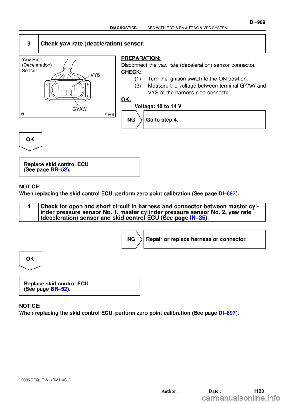
F19145
Yaw Rate
(Deceleration)
Sensor
VYS
GYAW
± DIAGNOSTICSABS WITH EBD & BA & TRAC & VSC SYSTEM
DI±989
1183 Author�: Date�:
2005 SEQUOIA (RM1146U)
3 Check yaw rate (deceleration) sensor.
PREPARATION:
Disconnect the yaw rate (deceleration) sensor connector.
CHECK:
(1) Turn the ignition switch to the ON position.
(2) Measure the voltage between terminal GYAW and
VYS of the harness side connector.
OK:
Voltage: 10 to 14 V
NG Go to step 4.
OK
Replace skid control ECU
(See page BR±52).
NOTICE:
When replacing the skid control ECU, perform zero point calibration (See page DI±897).
4 Check for open and short circuit in harness and connector between master cyl-
inder pressure sensor No. 1, master cylinder pressure sensor No. 2, yaw rate
(deceleration) sensor and skid control ECU (See page IN±35).
NG Repair or replace harness or connector.
OK
Replace skid control ECU
(See page BR±52).
NOTICE:
When replacing the skid control ECU, perform zero point calibration (See page DI±897).
Page 1194 of 4323
F19145
Yaw Rate
(Deceleration)
Sensor
STS
DI±992
± DIAGNOSTICSABS WITH EBD & BA & TRAC & VSC SYSTEM
1186 Author�: Date�:
2005 SEQUOIA (RM1146U)
INSPECTION PROCEDURE
1 Check voltage between terminal STS of brake pedal force switch and body
ground.
PREPARATION:
Disconnect the brake pedal force switch connector.
CHECK:
(a) Turn the ignition switch to the ON position.
(b) Measure the voltage between STS of brake pedal force
switch harness side connector and body ground.
OK:
Voltage: About 6 V
NG Go to step 3.
OK
Page 1195 of 4323

5
(Oscilloscope)
ON
F17283
(Reference)IG ON Released Depressed
0 V
6 V
0 V 6 VPSNC±STS
PSNO±STS
F13990
5
21
ON
± DIAGNOSTICSABS WITH EBD & BA & TRAC & VSC SYSTEM
DI±993
11")
F13989
1
2(Oscilloscope)
5
(Oscilloscope)
ON
F17283
(Reference)IG ON Released Depressed
0 V
6 V
0 V 6 VPSNC±STS
PSNO±STS
F13990
5
21
ON
± DIAGNOSTICSABS WITH EBD & BA & TRAC & VSC SYSTEM
DI±993
1187 Author�: Date�:
2005 SEQUOIA (RM1146U)
2 Check booster pedal force switch.
When using the oscilloscope:
PREPARATION:
(a) Connect the oscilloscope between terminals PSNO(1)
and STS(5), PSNC(2) and STS(5) of the brake booster
with connector being connected.
(b) Turn the ignition switch to the ON position.
CHECK:
Check the signal waveform while the brake pedal is depressed
and released.
OK:
When not using the oscilloscope:
PREPARATION:
(a) Disconnect the connector from the brake booster.
(b) Turn the ignition switch to the ON position.
CHECK:
Check continuity between the terminals while depressing and
releasing the brake pedal.
OK:
Tester ConnectionConditionSpecified Condition
Terminals 2 ± 5ReleasedContinuity
Terminals 1 ± 5DepressedContinuity
NG Replace brake booster
(See page BR±22).
OK
Page 1202 of 4323
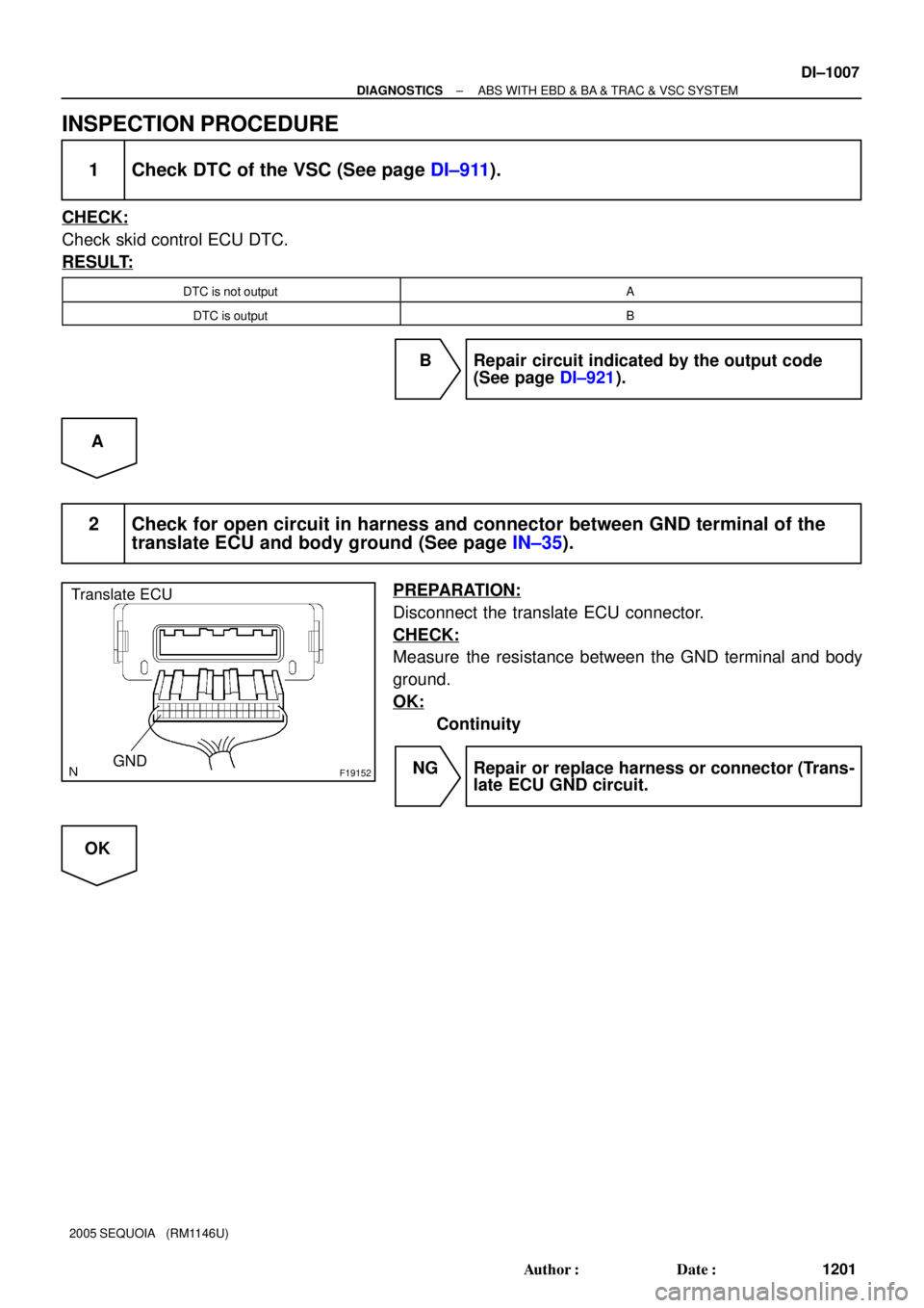
F19152
Translate ECU
GND
DI±1000
± DIAGNOSTICSABS WITH EBD & BA & TRAC & VSC SYSTEM
1194 Author�: Date�:
2005 SEQUOIA (RM1146U)
INSPECTION PROCEDURE
1 Check the DTC of the VSC (See page DI±911).
CHECK:
Check skid control ECU DTC.
RESULT:
DTC is not outputA
DTC (C1203/53) is outputB
B Repair circuit indicated by the output code
(See page DI±921).
A
2 Check for open circuit in harness and connector between GND terminal of the
translate ECU and body ground.
PREPARATION:
Disconnect the translate ECU connector.
CHECK:
Measure the resistance between the GND terminal and body
ground.
OK:
Continuity
NG Repair or replace harness or connector (Trans-
late ECU GND circuit).
OK
Page 1209 of 4323
F19152
Translate ECU
GND
± DIAGNOSTICSABS WITH EBD & BA & TRAC & VSC SYSTEM
DI±1007
1201 Author�: Date�:
2005 SEQUOIA (RM1146U)
INSPECTION PROCEDURE
1 Check DTC of the VSC (See page DI±911).
CHECK:
Check skid control ECU DTC.
RESULT:
DTC is not outputA
DTC is outputB
B Repair circuit indicated by the output code
(See page DI±921).
A
2 Check for open circuit in harness and connector between GND terminal of the
translate ECU and body ground (See page IN±35).
PREPARATION:
Disconnect the translate ECU connector.
CHECK:
Measure the resistance between the GND terminal and body
ground.
OK:
Continuity
NG Repair or replace harness or connector (Trans-
late ECU GND circuit.
OK
Page 1213 of 4323
F19152
Translate ECU
GND
± DIAGNOSTICSABS WITH EBD & BA & TRAC & VSC SYSTEM
DI±1011
1205 Author�: Date�:
2005 SEQUOIA (RM1146U)
INSPECTION PROCEDURE
1 Check DTC of the VSC (See page DI±911)
CHECK:
Check skid control ECU DTC.
RESULT:
DTC is not outputA
DTC is outputB
B Repair circuit indicated by the output code
(See page DI±921).
A
2 Check for open circuit in harness and connector between GND terminal of the
translate ECU and body ground (See page IN±35).
PREPARATION:
Disconnect the translate ECU connector.
CHECK:
Measure the resistance between the GND terminal and body
ground.
OK:
Continuity
NG Repair or replace harness or connector (Trans-
late ECU GND circuit).
OK