Page 1272 of 4323
F16975
Translate ECU:
T5 ENG+
ENG±
12345678
9 10111213141516
F19737F19152F19830
Translate ECU Wire Harness View:
T5
GND
ENG±
ENG+
DLC3:
D6
BAT
DI±1070
± DIAGNOSTICSCAN COMMUNICATION SYSTEM
1264 Author�: Date�:
2005 SEQUOIA (RM1146U)
4. Translate ECU
(a) Measure the resistance according to the value(s) in the
table below.
Standard:
TerminalsConditionSpecified Value
T5±14 (ENG+) ± T5±16 (ENG±)Ignition Switch OFF108 to 132 W
(b) Measure the resistance according to the value(s) in the
table below.
Standard:
TerminalsWiring ColorConditionSpecified Value
T5±14 (ENG+) ± T5±16 (ENG±)R ± WIgnition Switch OFF108 to 132 W
T5±14 (ENG+) ± T5±40 (GND)R ± OIgnition Switch OFF3 kW or more
T5±16 (ENG±) ± T5±40 (GND)W ± OIgnition Switch OFF3 kW or more
T5±14 (ENG+) ± D6±16 (BAT)R ± W±RIgnition Switch OFF1 MW or more
T5±16 (ENG±) ± D6±16 (BAT)W ± W±RIgnition Switch OFF1 MW or more
Page 1273 of 4323
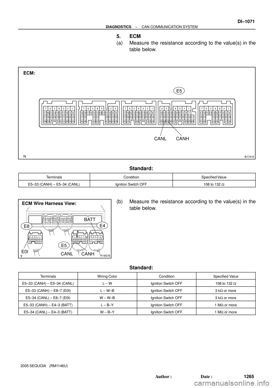
B17410
ECM:
CANL CANHE5
F19578
ECM Wire Harness View:
E4
E5
E8
BATT
E0ICANLCANH
± DIAGNOSTICSCAN COMMUNICATION SYSTEM
DI±1071
1265 Author�: Date�:
2005 SEQUOIA (RM1146U)
5. ECM
(a) Measure the resistance according to the value(s) in the
table below.
Standard:
TerminalsConditionSpecified Value
E5±33 (CANH) ± E5±34 (CANL)Ignition Switch OFF108 to 132 W
(b) Measure the resistance according to the value(s) in the
table below.
Standard:
TerminalsWiring ColorConditionSpecified Value
E5±33 (CANH) ± E5±34 (CANL)L ± WIgnition Switch OFF108 to 132 W
E5±33 (CANH) ± E8±7 (E0I)L ± W±BIgnition Switch OFF3 kW or more
E5±34 (CANL) ± E8±7 (E0I)W ± W±BIgnition Switch OFF3 kW or more
E5±33 (CANH) ± E4±3 (BATT)L ± B±YIgnition Switch OFF1 MW or more
E5±34 (CANL) ± E4±3 (BATT)W ± B±YIgnition Switch OFF1 MW or more
Page 1274 of 4323
F16805
Suspension Control ECU
Wire Harness View:
S25 GND BAT
CANH
CANL
DI±1072
± DIAGNOSTICSCAN COMMUNICATION SYSTEM
1266 Author�: Date�:
2005 SEQUOIA (RM1146U)
6. Suspension Control ECU
(a) Measure the resistance according to the value(s) in the
table below.
Standard:
TerminalsWiring ColorConditionSpecified Value
S25±29 (CANH) ± S25±28 (CANL)G ± WIgnition Switch OFF54 to 69 W
S25±29 (CANH) ± S25±22 (GND)G ± W±BIgnition Switch OFF3 kW or more
S25±28 (CANL) ± S25±22 (GND)W ± W±BIgnition Switch OFF3 kW or more
S25±29 (CANH) ± S25±25 (BAT)G ± VIgnition Switch OFF1 MW or more
S25±28 (CANL) ± S25±25 (BAT)W ± VIgnition Switch OFF1 MW or more
Page 1288 of 4323
F19701
Translate ECU
ENG+
ENG±Junction Connector
14
T5
16
T5R
W1
J55
2
J551
J53
2
J53L
W33
E5
34
E5ECM
CANH
CANL
D6 DLC3
1
J54
2
J54B
W6
14CANH
CANL DI±1086
± DIAGNOSTICSCAN COMMUNICATION SYSTEM
1280 Author�: Date�:
2005 SEQUOIA (RM1146U)
Check CAN Main Bus Line For Disconnection
CIRCUIT DESCRIPTION
The CAN main bus line and DLC3 sub bus line may have a disconnection when the resistance between ter-
minals 6 (CANH) and 14 (CANL) of the DLC3 is more than 69 W.
SymptomTrouble Area
Resistance between terminals 6 (CANH) and 14 (CANL) of
the DLC3 is more than 69 W.
�CAN main bus line
�ECM
�Translate ECU
�DLC3 sub bus line
WIRING DIAGRAM
DIDIC±01
Page 1290 of 4323
F19749
Junction Connector ºAº Side
(w/ Earth Terminal)
Wire Harness View:
Earth Terminal
CANL L
J53
WCANH
DI±1088
± DIAGNOSTICSCAN COMMUNICATION SYSTEM
1282 Author�: Date�:
2005 SEQUOIA (RM1146U)
2 Check CAN main bus line for disconnection (ECM ± Junction connector).
PREPARATION:
Disconnect the ECM main bus line connector (J53) from the
junction connector.
NOTICE:
�Before disconnecting the connector, make a note of
where it is connected.
�Reconnect the connector to its original position.
CHECK:
Measure the resistance according to the value(s) in the table
below.
OK:
Tester connectionConditionSpecified value
J53±1 (CANH) ±
J53±2 (CANL)Ignition switch OFF108 to 132 W
NG Go to step 5.
OK
3 Connect the connector.
Reconnect the ECM main line connector (J53) to the junction connector.
NEXT
Page 1291 of 4323
F19749
J55
R
W Junction Connector ºAº Side
(w/ Earth Terminal)
Wire Harness View:
CANL CANH
Earth Terminal
± DIAGNOSTICSCAN COMMUNICATION SYSTEM
DI±1089
1283 Author�: Date�:
2005 SEQUOIA (RM1146U)
4 Check CAN main bus line for disconnection (Translate ECU ± Junction connec-
tor).
PREPARATION:
Disconnect the translate ECU main bus line connector (J55)
from the junction connector.
NOTICE:
�Before disconnecting the connector, make a note of
where it is connected.
�Reconnect the connector to its original position.
CHECK:
Measure the resistance according to the value(s) in the table
below.
OK:
Tester connectionConditionSpecified value
J55±1 (CANH) ±
J55±2 (CANL)Ignition Switch OFF108 to 132 W
NG Go to step 7.
OK
Replace junction connector.
5 Connect the connector.
Reconnect the ECM main bus line connector (J53) to the junction connector.
NEXT
Page 1294 of 4323
F19702
ECM
CANH
CANL
ENG+
ENG± CANH
CANL
CANH
CANL D6 DLC3
Translate ECU
Suspension Control ECU33
E5
34
E5L
W1
J53
2
J53Junction Connector
1
J54
2
J54 B
W 6
14
14
T5
16
T51
J55
2
J55 R
W
29
S25
28
S25G
W (*1)
(*1)1
J56
2
J56
*1: w/ Air Suspension System DI±1092
± DIAGNOSTICSCAN COMMUNICATION SYSTEM
1286 Author�: Date�:
2005 SEQUOIA (RM1146U)
Check CAN Bus Lines For Short Circuit
CIRCUIT DESCRIPTION
There may be a short circuit between the CAN bus lines when the resistance between terminals 6 (CANH)
and 14 (CANL) of the DLC3 is below 54 W.
SymptomTrouble Area
Resistance between terminals 6 (CANH) and 14 (CANL) of
the DLC3 is below 54 W.
�Short between CAN bus lines
�Translate ECU
�Suspension control ECU
�ECM
�Junction connector
WIRING DIAGRAM
DIDID±01
Page 1295 of 4323
F19749
Junction Connector ºAº Side
(w/ Earth Terminal)
Wire Harness View:
J54
W B
Earth Terminal
12345678
9 10111213141516
F19737
DLC3:
D6CANH
CANL
± DIAGNOSTICSCAN COMMUNICATION SYSTEM
DI±1093
1287 Author�: Date�:
2005 SEQUOIA (RM1146U)
INSPECTION PROCEDURE
1 Check CAN bus lines for short circuit (DLC3 sub bus line).
PREPARATION:
Disconnect the DLC3 sub bus line connector (J54) from the
junction connector.
NOTICE:
�Before disconnecting the connector, make a note of
where it is connected.
�Reconnect the connector to its original position.
CHECK:
Measure the resistance according to the value(s) in the table
below.
OK:
Tester connectionConditionSpecified value
D6±6 (CANH) ±
D6±14 (CANL)Ignition Switch OFF1 MW or more
NG Repair or replace DLC3 sub bus line or connec-
tor (CAN±H, CAN±L).
OK
2 Connect the connector.
Reconnect the DLC3 sub bus line connector (J54) to the junction connector.
NEXT


Wire Harness View:
J54
W B
Earth Terminal
12345678
9 10111213141516
F19737
DLC3:
D6CANH
CANL
± DIAGNOSTICSCAN COMMUNICATION SYSTEM
DI±1093
1")