Page 1217 of 4323
± DIAGNOSTICSABS WITH EBD & BA & TRAC & VSC SYSTEM
DI±1015
1209 Author�: Date�:
2005 SEQUOIA (RM1146U)
DTC Non ± Code Translate ECU malfunction
CIRCUIT DESCRIPTION
Translate ECU DTCs can be read by blinks of the brake warning light (see page DI±911).
DTC No.DTC Detecting ConditionTrouble Area
Non ± code*Translate ECU internal malfunction is detected.
�Brake warning light circuit
�Tc terminal circuit
�Translate ECU
*: Neither the normal system code nor a trouble code is output.
INSPECTION PROCEDURE
1 Check the BRAKE warning light circuit (See page DI±1033).
OK:
BRAKE warning light circuit is normal.
NG Repair or replace the BRAKE warning light cir-
cuit.
OK
2 Check the Tc terminal circuit (See page DI±1055).
OK:
Tc terminal circuit is normal.
NG Repair or replace the Tc terminal circuit.
OK
Check and replace the translate ECU.
DI942±03
Page 1220 of 4323
F16990
ON
IG1
GND
DI±1018
± DIAGNOSTICSABS WITH EBD & BA & TRAC & VSC SYSTEM
1212 Author�: Date�:
2005 SEQUOIA (RM1146U)
INSPECTION PROCEDURE
1 Is DTC output?
Check DTC on page DI±911.
YES Repair circuit indicated by the output code
(See page DI±921).
NO
2 Check that the skid control ECU connector is securely connected to the skid
control ECU (See page IN±35).
NG Connect the connector to the skid control ECU.
OK
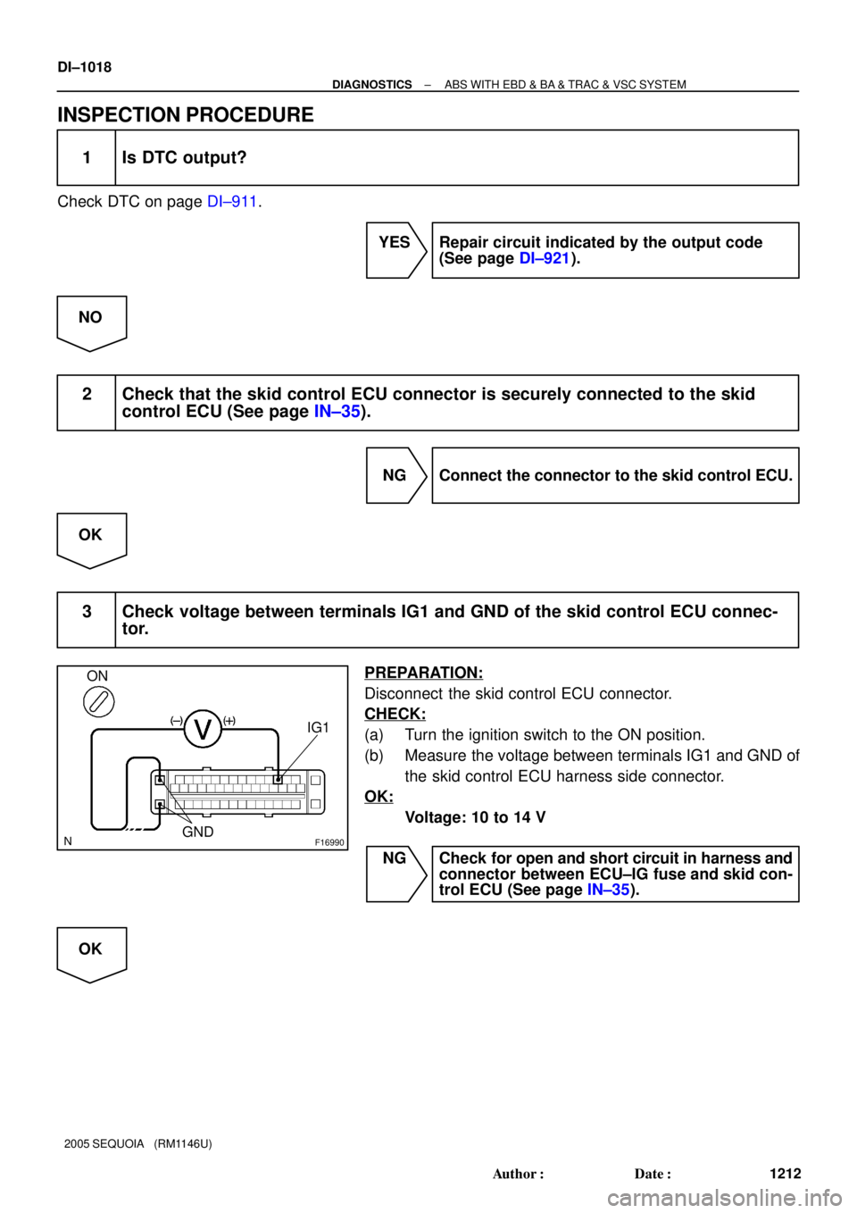
3 Check voltage between terminals IG1 and GND of the skid control ECU connec-
tor.
PREPARATION:
Disconnect the skid control ECU connector.
CHECK:
(a) Turn the ignition switch to the ON position.
(b) Measure the voltage between terminals IG1 and GND of
the skid control ECU harness side connector.
OK:
Voltage: 10 to 14 V
NG Check for open and short circuit in harness and
connector between ECU±IG fuse and skid con-
trol ECU (See page IN±35).
OK
Page 1221 of 4323
± DIAGNOSTICSABS WITH EBD & BA & TRAC & VSC SYSTEM
DI±1019
1213 Author�: Date�:
2005 SEQUOIA (RM1146U)
4 Check battery positive voltage.
CHECK:
Check the battery positive voltage.
OK:
Voltage: 10 to 14 V
NG Check and repair the charging system
(See page CH±1).
OK
5 Check the Tc terminal circuit (See page DI±1055).
OK:
Tc terminal circuit is normal
NG Repair or replace the Tc terminal circuit.
OK
Page 1223 of 4323
± DIAGNOSTICSABS WITH EBD & BA & TRAC & VSC SYSTEM
DI±1021
1215 Author�: Date�:
2005 SEQUOIA (RM1146U)
ABS Warning Light Circuit (Remains ON)
CIRCUIT DESCRIPTION
If the ECU detects trouble, it turns on the ABS warning light and prohibits ABS control. At this time, the ECU
records a DTC in memory.
Connect terminals Tc and CG of the DLC3 to make the ABS warning light blink and indicate the DTC.
DI944±04
Page 1252 of 4323

INSPECTION PROCEDURE
HINT:
Star")
F13991
GNDCSW*1
Center Integration Panel Assembly
CSW
*2
C3C6
DI±1050
± DIAGNOSTICSABS WITH EBD & BA & TRAC & VSC SYSTEM
1244 Author�: Date�:
2005 SEQUOIA (RM1146U)
INSPECTION PROCEDURE
HINT:
Start the inspection from step 1 when using the hand±held tester and start from step 2 when not using the
hand±held tester.
1 Check operation of the VSC OFF (TRAC OFF) indicator light.
PREPARATION:
(a) Connect the hand±held tester to the DLC3.
(b) Turn the ignition switch to the ON position and push the hand±held tester main switch ON.
(c) Select ACTIVE TEST mode on the hand±held tester.
CHECK:
Check that ºONº and ºOFFº of the VSC OFF (TRAC OFF) indicator light can be shown on the combination
meter with the hand±held tester.
ItemVehicle Condition / Test DetailsDiagnostic Note
VSC OFF (TRAC OFF)Turns VSC OFF (TRAC OFF) indicator ON / OFFObserve combination me-
ter
OK:
VSC OFF (TRAC OFF) indicator light comes on.
NG Go to step 4.
OK
2 Check center diff. lock (TRAC OFF) switch.
PREPARATION:
Remove center integration panel assembly (See page
BO±85).
CHECK:
Measure the resistance between terminals CSW and GND of
the center diff. lock
*1
(TRAC OFF *2) switch when the center diff.
lock
*1 (TRAC OFF *2) switch is ON and OFF.
*1
: Only for 4WD
*2 : Only for 2WD
OK:
Center diff. lock (TRAC OFF) switchResistance
Press continuouslyContinuity
Release1MW or higher
NG Replace center diff. lock (TRAC OFF) switch.
OK
Page 1253 of 4323
± DIAGNOSTICSABS WITH EBD & BA & TRAC & VSC SYSTEM
DI±1051
1245 Author�: Date�:
2005 SEQUOIA (RM1146U)
3 Check for open and short circuit in harness and connector between terminal
CSW of the translate ECU and center diff. lock (TRAC OFF) switch and body
ground (See page IN±35).
NG Repair or replace harness or connector.
OK
4 Check VSC OFF (TRAC OFF) indicator light.
See combination meter troubleshooting on page DI±1614.
NG Repair or replace combination meter
(See page DI±1610).
OK
5 Check for open and short circuit in harness and connector between terminal WT
of the translate ECU and VSC OFF (TRAC OFF) indicator light (See page
IN±35).
NG Repair or replace harness or connector.
OK
Check and replace translate ECU
Page 1255 of 4323

INSPECTION PROCEDURE
HINT:
Start the inspection from step 1 when using the hand±held tester")
± DIAGNOSTICSABS WITH EBD & BA & TRAC & VSC SYSTEM
DI±1053
1247 Author�: Date�:
2005 SEQUOIA (RM1146U)
INSPECTION PROCEDURE
HINT:
Start the inspection from step 1 when using the hand±held tester and start from step 2 when not using the
hand±held tester.
1 Check operation of the VSC buzzer.
PREPARATION:
(a) Connect the hand±held tester to the DLC3.
(b) Turn the ignition switch to the ON position and push the hand±held tester main switch ON.
(c) Select ACTIVE TEST mode on the hand±held tester.
CHECK:
Check ºON±OFFº function of the VSC buzzer with the hand±held tester.
ItemVehicle Condition / Test DetailsDiagnostic Note
VSC / BR WARN BUZTurns VSC / BRAKE warning buzzer ON / OFFBuzzer can be heard
OK:
Buzzer sound can be heard.
OK Replace skid control ECU
(See page BR±52).
NOTICE:
When replacing the skid control ECU, perform the zero
point calibration (See page DI±897).
NG
2 Check voltage between terminal 2 of the VSC buzzer and body ground.
PREPARATION:
Remove the VSC buzzer with connectors still connected.
CHECK:
(a) Turn the ignition switch to the ON position.
(b) Measure the voltage between terminal (2) of the VSC buzzer and body ground.
OK:
Voltage: 10 to 14 V
NG Repair or replace harness or connector from
voltage supply to VSC buzzer.
OK
Page 1256 of 4323
F02192
2
1 (+) (±)
DI±1054
± DIAGNOSTICSABS WITH EBD & BA & TRAC & VSC SYSTEM
1248 Author�: Date�:
2005 SEQUOIA (RM1146U)
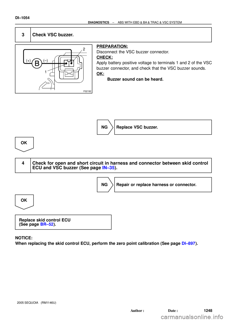
3 Check VSC buzzer.
PREPARATION:
Disconnect the VSC buzzer connector.
CHECK:
Apply battery positive voltage to terminals 1 and 2 of the VSC
buzzer connector, and check that the VSC buzzer sounds.
OK:
Buzzer sound can be heard.
NG Replace VSC buzzer.
OK
4 Check for open and short circuit in harness and connector between skid control
ECU and VSC buzzer (See page IN±35).
NG Repair or replace harness or connector.
OK
Replace skid control ECU
(See page BR±52).
NOTICE:
When replacing the skid control ECU, perform the zero point calibration (See page DI±897).