Page 871 of 4323

INSPECTION PROCEDURE
HINT:
According to the DATA LIST displayed by the OBD II scan tool or hand±held tester,")
± DIAGNOSTICSAUTOMATIC TRANSMISSION
DI±669
863 Author�: Date�:
2005 SEQUOIA (RM1146U)
INSPECTION PROCEDURE
HINT:
According to the DATA LIST displayed by the OBD II scan tool or hand±held tester, you can read the value
of the switch, sensor, actuator and so on without parts removal. Reading the DATA LIST as the first step of
troubleshooting is one method to shorten labor time.
(a) Warm up the engine.
(b) Turn the ignition switch off.
(c) Connect the OBD II scan tool or hand±held tester to the DLC3.
(d) Turn the ignition switch to the ON position.
(e) Push the ºONº button of the OBD II scan tool or the hand±held tester.
(f) When you use the hand±held tester:
Select the item ºDIAGNOSIS / ENHANCED OBD II / DATA LISTº.
(g) According to the display on the tester, read the ºDATA LISTº.
ItemMeasurement Item/
Range (display)Normal Condition
AT FLUID TEMP 2
ATF Temp. Sensor Value/
min.: ±40�C (±40�F)
max.: 215�C (419�F)�After Stall Test;
Approx. 80�C (176�F)
�Equal to ambient temperature when cold soak
HINT:
When DTC P2742 is output and hand±held tester output is 150�C (302�F) or more, there is a short circuit.
When DTC P2743 is output and hand±held tester output is ±40�C (±40�F), there is an open circuit.
Measure the resistance between terminal THO2 (OT2) and body ground.
Temperature DisplayedMalfunction
±40°C (±40°F)Open circuit
150°C (302°F) or moreShort circuit
Page 880 of 4323
D12795
12
(±)(+)
12
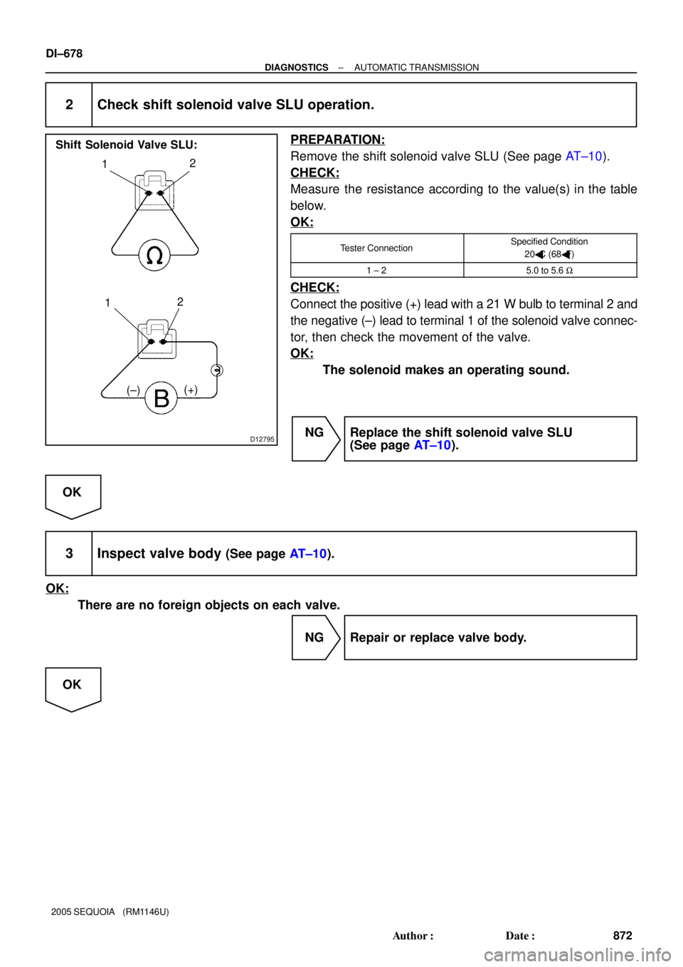
Shift Solenoid Valve SLU:
DI±678
± DIAGNOSTICSAUTOMATIC TRANSMISSION
872 Author�: Date�:
2005 SEQUOIA (RM1146U)
2 Check shift solenoid valve SLU operation.
PREPARATION:
Remove the shift solenoid valve SLU (See page AT±10).
CHECK:
Measure the resistance according to the value(s) in the table
below.
OK:
Tester ConnectionSpecified Condition
20�C (68�F)
1 ± 25.0 to 5.6 W
CHECK:
Connect the positive (+) lead with a 21 W bulb to terminal 2 and
the negative (±) lead to terminal 1 of the solenoid valve connec-
tor, then check the movement of the valve.
OK:
The solenoid makes an operating sound.
NG Replace the shift solenoid valve SLU
(See page AT±10).
OK
3 Inspect valve body (See page AT±10).
OK:
There are no foreign objects on each valve.
NG Repair or replace valve body.
OK
Page 886 of 4323
D12795
12
(±)(+)
12
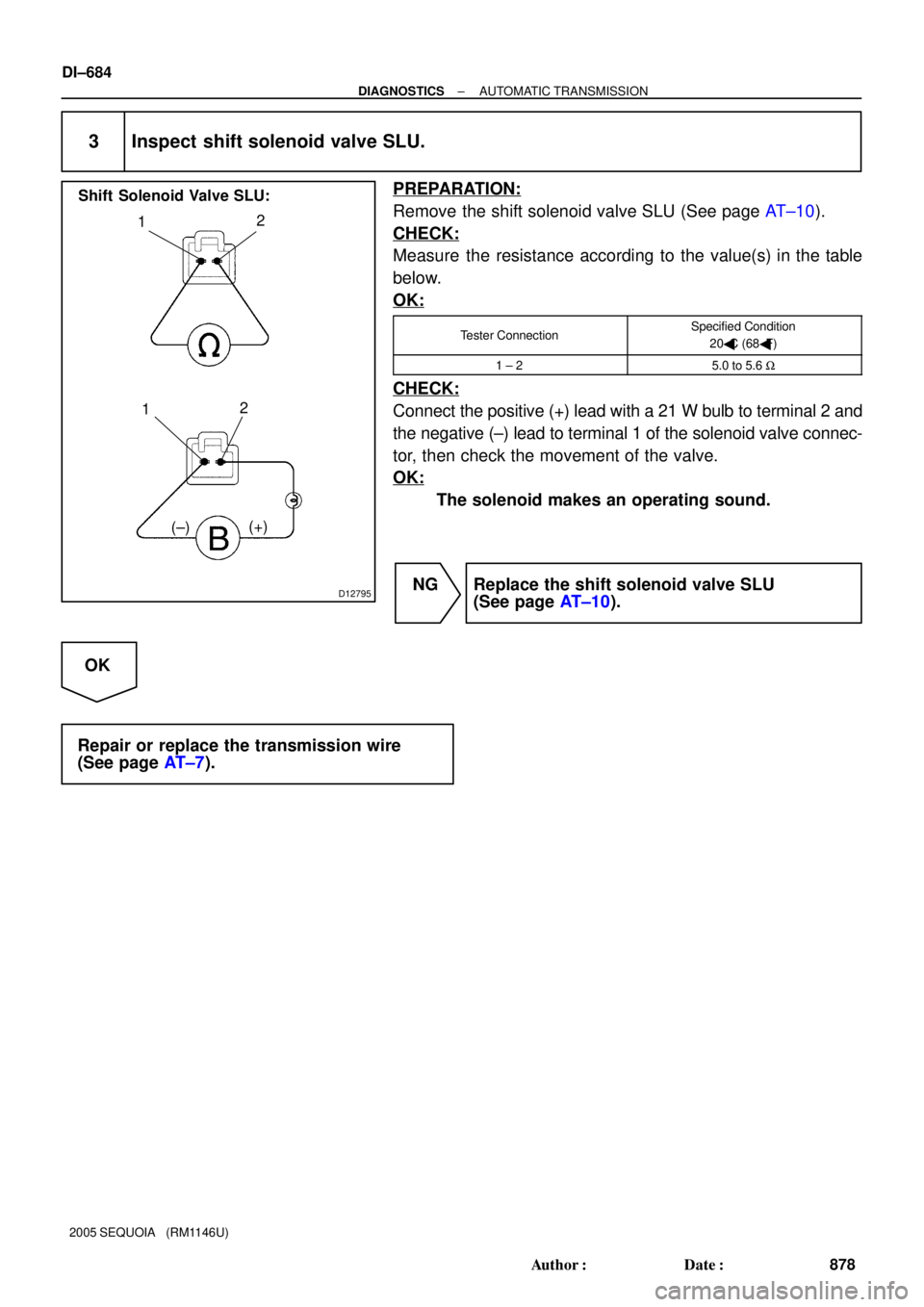
Shift Solenoid Valve SLU:
DI±684
± DIAGNOSTICSAUTOMATIC TRANSMISSION
878 Author�: Date�:
2005 SEQUOIA (RM1146U)
3 Inspect shift solenoid valve SLU.
PREPARATION:
Remove the shift solenoid valve SLU (See page AT±10).
CHECK:
Measure the resistance according to the value(s) in the table
below.
OK:
Tester ConnectionSpecified Condition
20�C (68�F)
1 ± 25.0 to 5.6 W
CHECK:
Connect the positive (+) lead with a 21 W bulb to terminal 2 and
the negative (±) lead to terminal 1 of the solenoid valve connec-
tor, then check the movement of the valve.
OK:
The solenoid makes an operating sound.
NG Replace the shift solenoid valve SLU
(See page AT±10).
OK
Repair or replace the transmission wire
(See page AT±7).
Page 889 of 4323
D14237L4
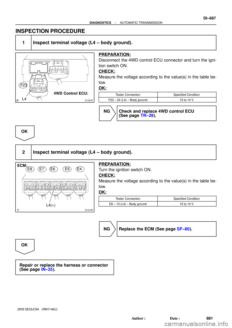
4WD Control ECU: F23
D14167
ECM:
E8E7E6E5E4
L4(+)
± DIAGNOSTICSAUTOMATIC TRANSMISSION
DI±687
881 Author�: Date�:
2005 SEQUOIA (RM1146U)
INSPECTION PROCEDURE
1 Inspect terminal voltage (L4 ± body ground).
PREPARATION:
Disconnect the 4WD control ECU connector and turn the igni-
tion switch ON.
CHECK:
Measure the voltage according to the value(s) in the table be-
low.
OK:
Tester ConnectionSpecified Condition
F23 ± 24 (L4) ± Body ground10 to 14 V
NG Check and replace 4WD control ECU
(See page TR±39).
OK
2 Inspect terminal voltage (L4 ± body ground).
PREPARATION:
Turn the ignition switch ON.
CHECK:
Measure the voltage according to the value(s) in the table be-
low.
OK:
Tester ConnectionSpecified Condition
E6 ± 13 (L4) ± Body ground10 to 14 V
NG Replace the ECM (See page SF±80).
OK
Repair or replace the harness or connector
(See page IN±35).
Page 897 of 4323
DIDCB±01
± DIAGNOSTICSAIR SUSPENSION SYSTEM
DI±695
889 Author�: Date�:
2005 SEQUOIA (RM1146U)
AIR SUSPENSION SYSTEM
PRECAUTION
Be sure to switch the height control mode select switch to manual mode and cancel the auto leveling
function when:
�Jacking up the vehicle.
�A trailer etc. is attached to the vehicle.
NOTICE:
When disconnecting the battery terminal, initialize the following system after the terminal is recon-
nected.
System NameSee Page
Back Door Power Window Control SystemBE±77
Page 913 of 4323

TEST MODE PROCEDURE
1. INPUT SIGNAL")
DIDCV±01
C00083
DLC3
CG TS
F16800
Height
Control
Manual
Indicator
Lamp
± DIAGNOSTICSAIR SUSPENSION SYSTEM
DI±711
905 Author�: Date�:
2005 SEQUOIA (RM1146U)
TEST MODE PROCEDURE
1. INPUT SIGNAL CHECK (Using SST check wire)
HINT:
�This function checks if signals from the stop light switch
assy and the door courtesy lamp switch, etc. are being in-
put normally to the ECU.
�When entering test mode, the suspension control ECU
sets all the test mode DTCs first.
After completing the test mode for each check item, the
test mode DTCs that are determined normal by the sus-
pension control ECU will be erased.
The test mode DTCs for other check items may not be
erased when only a certain signal is inspected.
�When the test mode returns back to normal mode, all the
test mode DTCs will be erased.
(a) Procedure for Input Signal Check Mode (Test Mode) us-
ing SST check wire.
SST 09843±18040
(1) Make sure the ignition switch is OFF.
(2) Set each of the check items to the condition shown
under Operation (A) in the test mode table on the
next page.
(3) Using SST, connect terminals TS and CG of the
DLC3.
(4) Turn the ignition switch to the ON position.
(5) Check that the height control manual indicator lamp
is blinking.
HINT:
�The height control manual indicator lamp comes on for 2
seconds, then blinks at 0.25 sec. intervals.
�If the height control manual indicator light does not blink,
inspect the height control manual indicator lamp circuit
(See page DI±789).
Page 914 of 4323

�The TS terminal circuit uses CAN (Control")
C00083
DLC3
CG TC
TS
F16800
Height
Control
Manual
Indicator
Lamp
DI±712
± DIAGNOSTICSAIR SUSPENSION SYSTEM
906 Author�: Date�:
2005 SEQUOIA (RM1146U)
�The TS terminal circuit uses CAN (Controller Area Net-
work) for communication. Therefore, if there are any mal-
functions in the communication circuit, one or more DTCs
in the CAN communication system is/are output.
(6) Set each of the check items to the condition shown
under Operation (B) in the test mode table below.
HINT:
When checking each item, the height control manual indicator
lamp comes on for 1 second.
Test mode table:
Check ItemOperation (A)Operation (B)
Stop light switch signalOFF (Brake pedal not depressed)ON (Brake pedal depressed)
Door courtesy light switch signalON (Each door opened)OFF (All doors closed)
Height control switch signal±Press the height control switch ºUPº first and
then press ºDOWNº
Height control mode select switch signalOFF (Height control mode select switch not
pushed in)ON to OFF (Height control mode select switch
pushed in and released)
(7) Using SST, connect the 3rd terminal of the SST
check wire to terminal TC of the DLC3.
SST 09843±18040
(8) Read the number of blinks of the height control
manual indicator lamp.
Page 915 of 4323

HINT:
�As ex")
F16802
0.25 sec. 0.5 sec.
ON
OFF
0.25 sec.4.5 sec.
ON
OFF1.5 sec. Normal:
Code 82:
0.5 sec.
Repeat
± DIAGNOSTICSAIR SUSPENSION SYSTEM
DI±713
907 Author�: Date�:
2005 SEQUOIA (RM1146U)
HINT:
�As examples, the blinking patterns of a normal system
code and code 82 are shown in the illustration.
�If 2 or more malfunctions are indicated at the same time,
the lowest numbered code is displayed first.
�When a DTC is not output, check the TC terminal circuit
on page DI±1567.
(9) Check the malfunction using the code table on the
next page.
(b) Ending the Input Signal Check Mode (Test Mode) using
SST check wire.
SST 09843±18040
(1) With the ignition switch OFF, disconnect the SST
check wire from the terminals of the DLC3 and then
turn the ignition switch to the ON position.
(c) Procedure for Sensor Test Mode (Test Mode) using the
hand±held tester.
(1) Make sure the ignition switch is OFF.
(2) Set each of the check items to the condition shown
under Operation (A) in the test mode table on the
previous page.
(3) Connect the hand±held tester to the DLC3.
(4) Turn the ignition switch to the ON position.
(5) Select SIGNAL CHECK mode on the hand±held
tester.
(6) Set each of the check items to the condition shown
under Operation (B) in the test mode table on the
previous page.
HINT:
In step (6), all signals can be checked together.
(7) Read the DTCs by following the prompts on the tes-
ter screen.
HINT:
Refer to the hand±held tester operator's manual for further de-
tails.