Page 707 of 4323
D14154
Component Side:
A19288
± DIAGNOSTICSENGINE
DI±505
699 Author�: Date�:
2005 SEQUOIA (RM1146U)
4 Check park/neutral position switch.
PREPARATION:
Remove the P1 park/neutral position switch connector.
CHECK:
Check resistance between each terminal shown below when
the shift lever is moved to each range.
Shift rangeTerminal No. to continuity
P1 ± 36 ± 9
R2 ± 3±
N3 ± 56 ± 9
D3 ± 7±
23 ± 4±
L3 ± 8±
OK:
Below 1 W
NG Replace the park/neutral position switch.
OK
Check and repair harness and connector be-
tween park/neutral position switch and ECM.
5 Check starter relay.
(a) Remove the starter relay from the engine room R/B.
(b) Inspect the starter relay.
Standard:
Tester ConnectionSpecified Condition
3 ± 510 kW or higher
3 ± 5Below 1 W
(Apply battery voltage to terminals 1 and 2)
NG Replace starter relay.
OK
Page 708 of 4323

6 Check for open a")
A23563
Wire Harness Side
Park/Neutral position switch ConnectorN1
A21559
Engine Room R/B No.2
Starter Relay
DI±506
± DIAGNOSTICSENGINE
700 Author�: Date�:
2005 SEQUOIA (RM1146U)
6 Check for open and short in harness and connector between park/neutral posi-
tion switch and starter relay.
(a) Check the harness and the connector between the park/
neutral position switch connector and the starter relay.
(1) Disconnect the park/neutral position switch con-
nector.
(2) Remove the starter relay from the engine room R/B.
(3) Check for resistance between the wire harness side
connectors.
Standard (Check for open):
Symbols (Terminal No.)Specified condition
Park/Neutral position switch (N1±6) ± Starter relay (1)Below 1 W
Standard (Check for short):
Symbols (Terminal No.)Specified condition
Park/Neutral position switch (N1±6) or Starter relay (1)
± Body ground10 kW or higher
(b) Check the harness and the connector between the starter
relay and the body ground.
(1) Remove the starter relay from the engine room R/B.
(2) Check for resistance between the starter relay and
the body ground.
Standard (Check for open):
Symbols (Terminal No.)Specified condition
Starter relay (2) ± Body groundBelow 1 W
NG Repair or replace harness or connector.
OK
Page 709 of 4323
A21559
Engine Room R/B No.2
Starter Relay
± DIAGNOSTICSENGINE
DI±507
701 Author�: Date�:
2005 SEQUOIA (RM1146U)
7 Check engine room R/B No.2 (Starter relay voltage).
PREPARATION:
Remove the starter relay from the engine room R/B No.2.
CHECK:
Measure the voltage between the terminal of the engine room
R/B and body ground.
OK:
Standard:
Tester ConnectionSpecified Condition
Starter relay (5) ± Body ground9 to 14 V
NG Check and repair harness and connector be-
tween starter relay and battery.
OK
8 Check starter (See page ST±15).
NG Repair or replace starter.
OK
Page 710 of 4323
I08467
LOCKACC
ON
START
DI±508
± DIAGNOSTICSENGINE
702 Author�: Date�:
2005 SEQUOIA (RM1146U)
9 Check ignition switch.
PREPARATION:
(a) Remove the lower finish panel.
(b) Disconnect the ignition switch connector.
CHECK:
Check resistance between terminals.
OK:
Standard:
Switch PositionTerminal ConditionSpecified Condition
LOCKAlways10 kW or more
ACC1 ± 3Below 1 W
ON1 ± 2 ± 3
5 ± 6Below 1 W
START1 ± 2
4 ± 5 ± 6Below 1 W
NG Replace ignition switch.
OK
Check for open in harness and connector be-
tween ECM and ignition switch, ignition
switch and battery (See page IN±35).
Page 712 of 4323
A21024
A19288
DI±510
± DIAGNOSTICSENGINE
704 Author�: Date�:
2005 SEQUOIA (RM1146U)
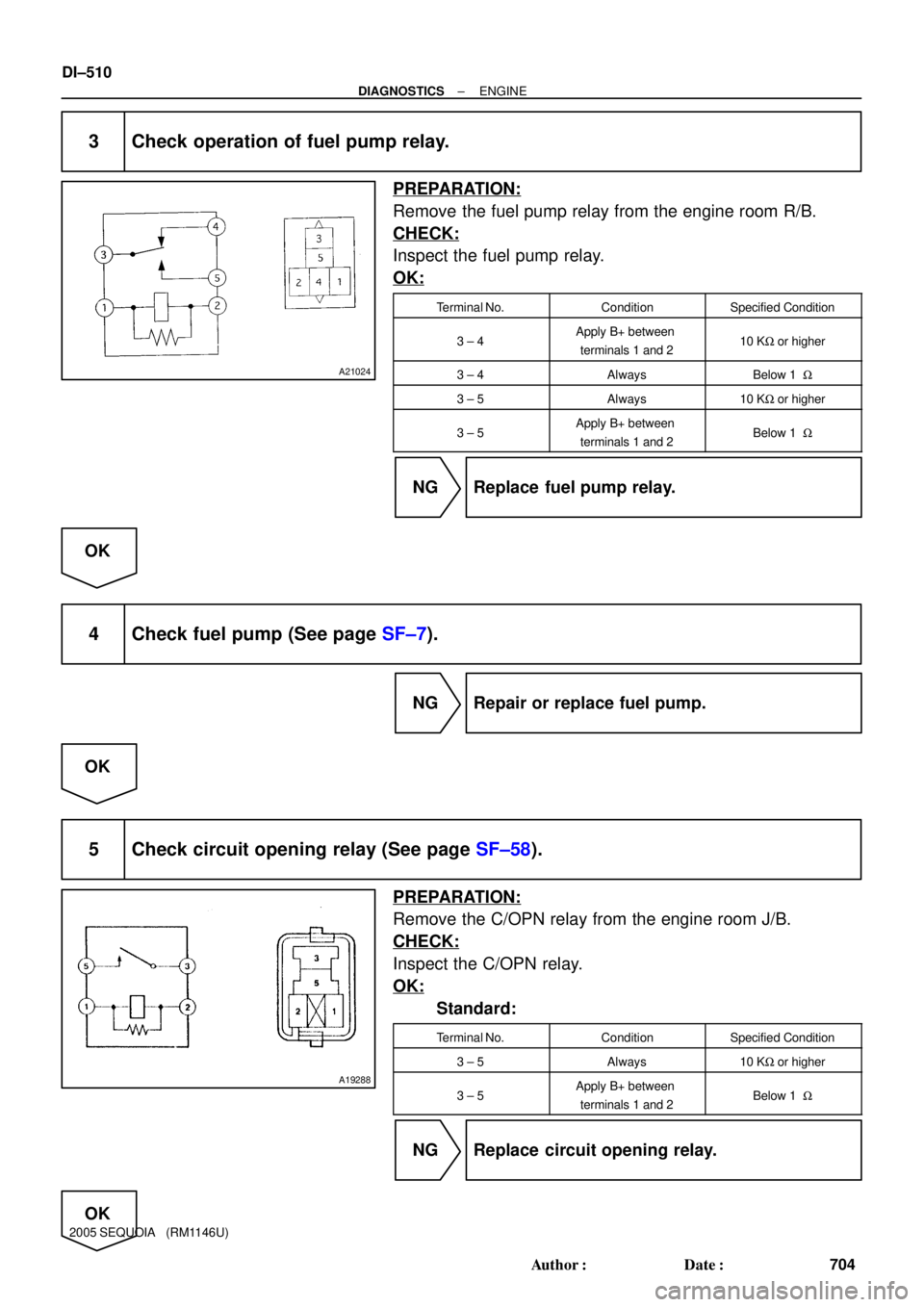
3 Check operation of fuel pump relay.
PREPARATION:
Remove the fuel pump relay from the engine room R/B.
CHECK:
Inspect the fuel pump relay.
OK:
Terminal No.ConditionSpecified Condition
3 ± 4Apply B+ between
terminals 1 and 210 KW or higher
3 ± 4AlwaysBelow 1 W
3 ± 5Always10 KW or higher
3 ± 5Apply B+ between
terminals 1 and 2Below 1 W
NG Replace fuel pump relay.
OK
4 Check fuel pump (See page SF±7).
NG Repair or replace fuel pump.
OK
5 Check circuit opening relay (See page SF±58).
PREPARATION:
Remove the C/OPN relay from the engine room J/B.
CHECK:
Inspect the C/OPN relay.
OK:
Standard:
Terminal No.ConditionSpecified Condition
3 ± 5Always10 KW or higher
3 ± 5Apply B+ between
terminals 1 and 2Below 1 W
NG Replace circuit opening relay.
OK
Page 713 of 4323
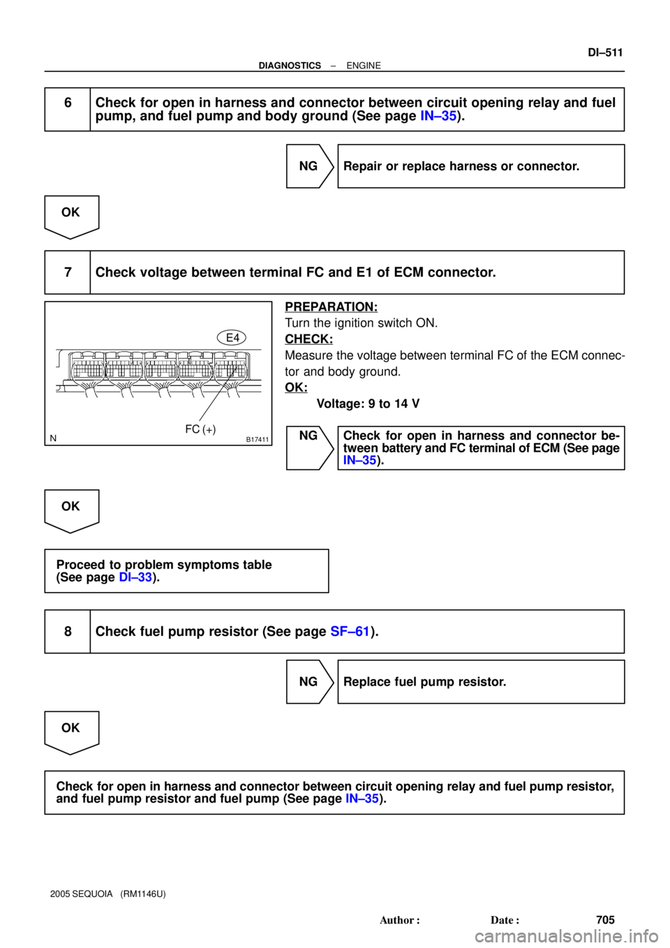
B17411FC (+)E4
± DIAGNOSTICSENGINE
DI±511
705 Author�: Date�:
2005 SEQUOIA (RM1146U)
6 Check for open in harness and connector between circuit opening relay and fuel
pump, and fuel pump and body ground (See page IN±35).
NG Repair or replace harness or connector.
OK
7 Check voltage between terminal FC and E1 of ECM connector.
PREPARATION:
Turn the ignition switch ON.
CHECK:
Measure the voltage between terminal FC of the ECM connec-
tor and body ground.
OK:
Voltage: 9 to 14 V
NG Check for open in harness and connector be-
tween battery and FC terminal of ECM (See page
IN±35).
OK
Proceed to problem symptoms table
(See page DI±33).
8 Check fuel pump resistor (See page SF±61).
NG Replace fuel pump resistor.
OK
Check for open in harness and connector between circuit opening relay and fuel pump resistor,
and fuel pump resistor and fuel pump (See page IN±35).
Page 717 of 4323
DIDIH±01
± DIAGNOSTICSAUTOMATIC TRANSMISSION
DI±515
709 Author�: Date�:
2005 SEQUOIA (RM1146U)
AUTOMATIC TRANSMISSION
PRECAUTION
NOTICE:
Perform the RESET MEMORY (AT initialization) when replacing the automatic transmission assy, en-
gine assy or ECM (See page DI±543).
HINT:
RESET MEMORY cannot be completed by only disconnecting the battery terminal.
NOTICE:
When disconnecting the battery terminal, initialize the following system after the terminal is recon-
nected.
System NameSee Page
Back Door Power Window Control SystemBE±77
Page 726 of 4323

BASIC INSPECTION
1. CHECK FLUID LEVEL
(a) Using")
DIDIP±01
12345678
9 10111213141516
D13649
DLC3:
CG
TC
D13654
DI±524
± DIAGNOSTICSAUTOMATIC TRANSMISSION
718 Author�: Date�:
2005 SEQUOIA (RM1146U)
BASIC INSPECTION
1. CHECK FLUID LEVEL
(a) Using SST, create a short±circuit between terminals TC
and CG of the DLC3.
SST 09843±18040
(b) Start the engine and run at idle.
�The A/C switch must be turned off.
�On models with active height control suspension &
adaptive variable suspension, turn the height con-
trol switch off.
(c) Slowly move the shift lever through all positions from P to
L, and move it back to the P position.
(d) Switch to the fluid temperature detection mode.
Move the shift lever from the N to the D position, or from
D to N, within 1.5 seconds. (Repeat this operation for 6 se-
conds or more.)
OK: The A/T OIL TEMP warning light comes on for 2
seconds and then goes off.
(e) Return the shift lever to the P position and disconnect ter-
minals TC and CG.
(f) Idle the engine to raise oil temperature.
(g) Lift up the vehicle immediately after the meter indicator
light (ATF temperature warning light) comes on.
�The A/T OIL TEMP warning light indicates the ATF
temperature according to the following table.
ATF Temp.Less than optimized
temperatureOptimized temperatureMore than optimized
temperature
A/T OIL TEMP warning lightOFFONBlinking