Page 688 of 4323
A23508
Wire Harness Side:
Canister Connector
Front View
L5
DI±486
± DIAGNOSTICSENGINE
680 Author�: Date�:
2005 SEQUOIA (RM1146U)
25 Check for open and short in harness and connector between pump module and
ECM.
PREPARATION:
(a) Disconnect the L5 canister connector.
(b) Turn the ignition switch to OFF.
CHECK:
Check the resistance between terminal 6 of the canister con-
nector and the body ground.
RESULT:
Test ResultsSuspected Trouble AreasProceed To
Below 1 WVacuum pumpA
10 kW or moreWire harness between vacuum pump and body
groundB
A Go to step 30.
B Go to step 32.
26 Inspect throttle body.
PREPARATION:
(a) Stop the engine.
(b) Disconnect the EVAP hose from the throttle body.
(c) Start the engine.
CHECK:
(a) Use your finger to confirm that the port of the throttle body has suction.
RESULT:
Test ResultsSuspected Trouble AreasProceed To
Suction appliedEVAP hose between throttle body and purge VSVA
No suctionThrottle bodyB
A Go to step 33.
B Go to step 34.
Page 695 of 4323
± DIAGNOSTICSENGINE
DI±493
687 Author�: Date�:
2005 SEQUOIA (RM1146U)
ECM Power Source Circuit
CIRCUIT DESCRIPTION
When the ignition switch is turned ON, battery positive voltage is applied to terminal IGSW of the ECM and
the EFI relay control circuit in the ECM sends a signal to terminal MREL of the ECM switching on the EFI
relay.
This signal causes current to flow to the coil, closing the contacts of the EFI relay and supplying power to
terminal +B of the ECM.
DID8K±01
Page 697 of 4323
B17411
+B E1(+)
(±)E6
E4
B17411
IGSW (+)E4
± DIAGNOSTICSENGINE
DI±495
689 Author�: Date�:
2005 SEQUOIA (RM1146U)
INSPECTION PROCEDURE
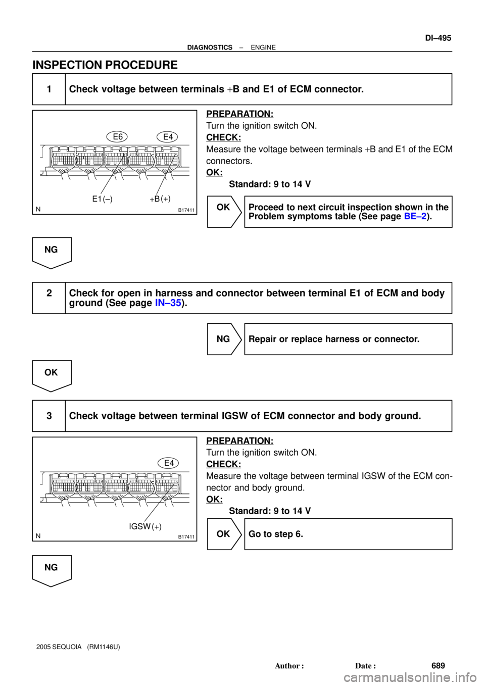
1 Check voltage between terminals +B and E1 of ECM connector.
PREPARATION:
Turn the ignition switch ON.
CHECK:
Measure the voltage between terminals +B and E1 of the ECM
connectors.
OK:
Standard: 9 to 14 V
OK Proceed to next circuit inspection shown in the
Problem symptoms table (See page BE±2).
NG
2 Check for open in harness and connector between terminal E1 of ECM and body
ground (See page IN±35).
NG Repair or replace harness or connector.
OK
3 Check voltage between terminal IGSW of ECM connector and body ground.
PREPARATION:
Turn the ignition switch ON.
CHECK:
Measure the voltage between terminal IGSW of the ECM con-
nector and body ground.
OK:
Standard: 9 to 14 V
OK Go to step 6.
NG
Page 698 of 4323
A21560
IGN1 Instrument
Panel J/B:
I08467
LOCKACC
ON
START
DI±496
± DIAGNOSTICSENGINE
690 Author�: Date�:
2005 SEQUOIA (RM1146U)
4 Check IGN1 fuse.
PREPARATION:
Remove the IGN1 fuse from the instrument panel J/B.
CHECK:
Check the resistance of the IGN1 fuse.
OK:
Below 1 W
NG Check for short in all harness and components
connected to IGN1 fuse.
OK
5 Check ignition switch (See page BE±24).
PREPARATION:
(a) Remove the lower finish panel.
(b) Disconnect the ignition switch connector.
CHECK:
Check resistance between terminals.
OK:
Standard:
Switch PositionTerminal ConditionSpecified Condition
LOCKAlways10 kW or more
ACC1 ± 3Below 1 W
ON1 ± 2 ± 3
5 ± 6Below 1 W
START1 ± 2
4 ± 5 ± 6Below 1 W
NG Replace ignition switch.
OK
Check and repair harness and connector be-
tween IGN fuse and ECM.
Page 699 of 4323
B17411MREL(+)E4
Engine Room
J/B:
A21381
EFI No. 1
Fuse
± DIAGNOSTICSENGINE
DI±497
691 Author�: Date�:
2005 SEQUOIA (RM1146U)
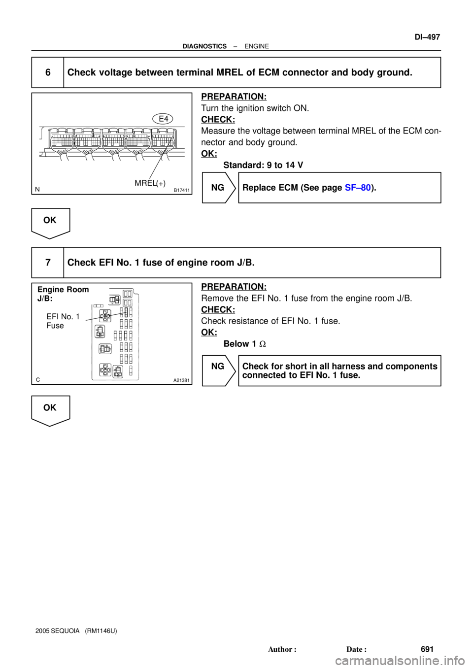
6 Check voltage between terminal MREL of ECM connector and body ground.
PREPARATION:
Turn the ignition switch ON.
CHECK:
Measure the voltage between terminal MREL of the ECM con-
nector and body ground.
OK:
Standard: 9 to 14 V
NG Replace ECM (See page SF±80).
OK
7 Check EFI No. 1 fuse of engine room J/B.
PREPARATION:
Remove the EFI No. 1 fuse from the engine room J/B.
CHECK:
Check resistance of EFI No. 1 fuse.
OK:
Below 1 W
NG Check for short in all harness and components
connected to EFI No. 1 fuse.
OK
Page 700 of 4323
A19288
EFI Relay
B17417
E4
MREL ECM Connector
DI±498
± DIAGNOSTICSENGINE
692 Author�: Date�:
2005 SEQUOIA (RM1146U)
8 Check EFI relay.
PREPARATION:
Remove the EFI relay from the engine room J/B.
CHECK:
Inspect the EFI relay.
OK:
Standard:
Terminal No.ConditionSpecified Condition
3 ± 5Always10 KW or higher
3 ± 5Apply B+ between
terminals 1 and 2Below 1 W
NG Replace EFI relay.
OK
9 Check for open and short in harness and connector between terminal MREL of
ECM and body ground.
PREPARATION:
Disconnect the E4 ECM connector.
CHECK:
Measure the resistance between the wire harness side connec-
tor and body ground.
OK:
Standard:
Tester ConnectionSpecified Condition
MREL (E4±8) ± Body groundBelow 1 W
NG Repair or replace harness or connector.
OK
Check for intermittent problems
(See page DI±11).
Page 704 of 4323

3 Check for open and short in harness and connector be")
A23670
Wire Harness Side
V12
VSV for ACIS connector
B17413
E5E7
E1
ACIS
DI±502
± DIAGNOSTICSENGINE
696 Author�: Date�:
2005 SEQUOIA (RM1146U)
3 Check for open and short in harness and connector between EFI main relay
(Marking: EFI) and ECM (See page IN±35).
(a) Check the wire harness between the VSV for ACIS and
connector the ECM connector.
(1) Disconnect the VSV for ACIS connector.
(2) Disconnect the E5 and E7 ECM connector.
(3) Check for resistance between the wire harness side
connectors.
Standard (Check for open):
Symbols (Terminal No.)Specified condition
VSV for ACIS (V12±2) ± ACIS (E5±33)Below 1 W
Standard (Check for short):
Symbols (Terminal No.)Specified condition
VSV for ACIS (V12±2) or ACIS (E5±33) ± E1 (E7±1)10 kW or higher
(b) Check the wire harness between the VSV for ACIS con-
nector and the EFI relay.
(1) Disconnect the VSV for ACIS connector.
(2) Remove the EFI relay from the engine room R/B.
(3) Check for resistance between the wire harness side
connectors.
Standard (Check for open):
Symbols (Terminal No.)Specified condition
VSV for ACIS (V12±1) ± EFI relay terminal 3 of R/BBelow 1 W
NG Repair or replace harness or connector.
OK
Check and replace ECM (See page IN±35).
Page 706 of 4323
 E1(±)
STSW(+)E6
DI±504
± DIAGNOSTICSENGINE
698 Author�: Date�:
2005 SEQUOIA (RM1146U)
2 Connect hand±held tester, and check STA signal.
PREPARATION:
(a) Connect the hand±held tes")
B17411
STA(+) E1(±)
STSW(+)E6
DI±504
± DIAGNOSTICSENGINE
698 Author�: Date�:
2005 SEQUOIA (RM1146U)
2 Connect hand±held tester, and check STA signal.
PREPARATION:
(a) Connect the hand±held tester to the DLC3.
(b) Turn the ignition switch ON, and push the hand±held tester main switch ON.
(c) Enter the following menu: DIAGNOSIS / ENHANCED OBD II / DATA LIST / ALL / STARTER SIG.
CHECK:
Read the STA signal on the hand±held tester while the starter operates.
OK:
Ignition Switch PositionONSTART
STARTER SIGOFFON
NG Go to step 5.
OK
3 Check voltage between terminal STAR, STSW and E1 of ECM connector.
CHECK:
Measure the voltage between the terminals of the E6 ECM con-
nectors, while cranking the engine (ignition switch START posi-
tion).
OK:
Standard:
Tester ConnectionSpecified Condition
STA (E6±11) ± E1 (E6±1)9 to 14 V
STSW (E6±12) ± E1 (E6±1)9 to 14 V
RESULT:
Terminal STARTerminal STSWProceed to
9 to 14 V9 to 14 VA
0 V9 to 14 VB
0 V0 VC
B Replace ECM (See page SF±80).
C Go to step 9.
A