Page 551 of 4323

B17411
E4
AIDI
± DIAGNOSTICSENGINE
DI±349
543 Author�: Date�:
2005 SEQUOIA (RM1146U)
2 Check voltage between AIDI terminal of ECM and body ground.
PREPARATION:
(a) Start the engine and warm it up.
(b) Turn the ignition switch to OFF.
(c) Connect a hand±held tester to the DLC3.
(d) Turn the ignition switch ON and turn the tester ON.
(e) Start the engine.
(f) Select the following menu items: DIAGNOSIS/EN-
HANCED OBD II/SYSTEM CHECK/AIR INJ CHECK/AU-
TOMATIC OPERATION
CHECK:
Measure the voltage between terminal E4±13 (AIDI) of the
ECM connector and body ground when the air injection system
is both ON and OFF.
RESULT:
ResultsSuspected Trouble AreasProceed To
Fixed at Low (1.6 V or less)
even when AI system ON
(Air pump ON, ASV ON)
�Short between air pump or air switching valve
command signal circuit and body ground
�Open in air pump command signal circuit (be-
tween ECM and AID)
�Open in ASV command signal circuit (between
ECM and AID)
�Open in AID ground circuit (between AID and
body ground)
�Diagnostic signal circuit ground short
�AID
�ECM
A
Fixed at High (12 V or more)
even when AI system OFF
(Air pump OFF, ASV OFF)
�Open in diagnostic signal circuit (ECM ± AID)
�Short between +B circuit and diagnostic signal
circuit (ECM ± AID)
�Open in AID power source circuit
�AID
�ECM
B
Other than above:
�Fluctuating (duty signal excluding 20, 40,
80%)�AID
�Open in AID ground circuit (between AID and
body ground)
C
B Go to step 5.
C Go to step 8.
A
Page 552 of 4323

B17411
E4
AIRVAIRP
B17444
Wire Harness Side:
Air Injection Driver Connector
A41
SIPSIVDI E
B17417
E4
AIRP
AIRV DI±350
± DIAGNOSTICSENGINE
544 Author�: Date�:
2005 SEQUOIA (RM1146U)
3 Check voltage between AIRP, AIRV terminals of ECM and body ground.
PREPARATION:
Turn the ignition switch ON.
CHECK:
Measure the voltage between terminals E4±25 (AIRP), E4±4
(AIRV) of the ECM connector, and body ground.
OK:
Tester ConnectionSpecified Condition
E4±25 (AIRP) ± Body ground10 V or more
E4±4 (AIRV) ± Body ground10 V or more
NG Replace ECM (See page SF±80).
OK
4 Check for short in harness and connector between SIP terminal of air injection
driver and SIRP of ECM.
PREPARATION:
(a) Disconnect the A41 air injection driver connector.
(b) Disconnect the E4 ECM connector.
CHECK:
Measure the resistance between the wire harness side connec-
tors.
OK:
Standard:
Tester ConnectionSpecified Condition
SIP (A41±4) or AIRP (E4±25) ±
Body ground10 kW or higher
SIV (A41±3) or AIRV (E4±4) ±
Body ground10 kW or higher
E (A41±1) ± Body groundBelow 1 W
CHECK:
Measure the voltage between terminals DI (A41±2) and E
(A41±1) of the air injection driver wire harness side connectors.
OK:
Standard:
Tester ConnectionSpecified Condition
DI (A41±2) ± E (A41±1)9 V or more
Page 553 of 4323

B17444
Wire Harness Side:
Air Injection Driver Connector
A41
+BE
B17444
Wire Harness Side:
Air Injection Driver Connector
A41
DI
± DIAGNOSTICSENGINE
DI±351
545 Author�: Date�:
2005 SEQUOIA (RM1146U)
NG Repair or replace harness or connector.
OK
Replace air injection driver.
5 Inspect air injection driver power source circuit.
PREPARATION:
(a) Disconnect the A41 air injection driver connector.
(b) Turn the ignition switch to ON.
CHECK:
Measure the voltage between terminals +B (A41±5) and E
(A41±1) of the air injection driver connector.
OK:
Standard:
Tester ConnectionSpecified Condition
A41±5 (+B) ± E (A41±1)10 V or more
NG Repair or replace harness or connector.
OK
6 Check voltage between DI terminals of air injection driver and body ground.
PREPARATION:
(a) Disconnect the A41 air injection driver connector.
(b) Turn the ignition switch to ON.
CHECK:
Measure the voltage between terminal A41±2 (DI) of the air in-
jection driver connector and body ground.
OK:
Standard:
Tester ConnectionSpecified Condition
A41±2 (DI) ± Body ground10 V or more
NG Go to step 7.
OK
Page 554 of 4323

B17444
Wire Harness Side:
Air Injection Driver Connector
A41
DI+B
B17417
E4
AIDI
B17444
Wire Harness Side:
Air Injection Driver Connector
A41
E
DI±352
± DIAGNOSTICSENGINE
546 Author�: Date�:
2005 SEQUOIA (RM1146U)
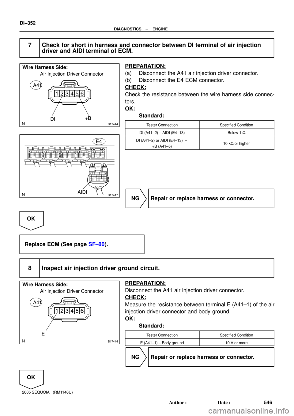
7 Check for short in harness and connector between DI terminal of air injection
driver and AIDI terminal of ECM.
PREPARATION:
(a) Disconnect the A41 air injection driver connector.
(b) Disconnect the E4 ECM connector.
CHECK:
Check the resistance between the wire harness side connec-
tors.
OK:
Standard:
Tester ConnectionSpecified Condition
DI (A41±2) ± AIDI (E4±13)Below 1 W
DI (A41±2) or AIDI (E4±13) ±
+B (A41±5)10 kW or higher
NG Repair or replace harness or connector.
OK
Replace ECM (See page SF±80).
8 Inspect air injection driver ground circuit.
PREPARATION:
Disconnect the A41 air injection driver connector.
CHECK:
Measure the resistance between terminal E (A41±1) of the air
injection driver connector and body ground.
OK:
Standard:
Tester ConnectionSpecified Condition
E (A41±1) ± Body ground10 V or more
NG Repair or replace harness or connector.
OK
Page 558 of 4323
A21034
T14
Component Side:
M+M± Throttle Control Motor and Sensor
DI±356
± DIAGNOSTICSENGINE
550 Author�: Date�:
2005 SEQUOIA (RM1146U)
INSPECTION PROCEDURE
HINT:
Read freeze frame data using the hand-held tester. Freeze frame data records the engine conditions when
a malfunction is detected. When troubleshooting, freeze frame data can help determine if the vehicle was
running or stopped, if the engine was warmed up or not, if the air±fuel ratio was lean or rich, as well as other
data from the time when a malfunction occurred.
1 Check throttle control motor.
PREPARATION:
Disconnect the throttle control motor and sensor connector.
CHECK:
Measure the resistance between terminals of the throttle con-
trol motor.
OK:
Standard:
Tester ConnectionSpecified Condition
M+ (T14±2) ± M± (T14±1)0.3 to100 W (20°C (68°F))
NG Replace throttle body (See page SF±39).
OK
Page 563 of 4323

A21034
T14
Component Side:
M+M± Throttle Control Motor and Sensor
A21022
T14
M+ M±
Wire Harness Side:
Throttle Control Motor and Sensor
B17412M+
M±
E8ECM Connector
± DIAGNOSTICSENGINE
DI±361
555 Author�: Date�:
2005 SEQUOIA (RM1146U)
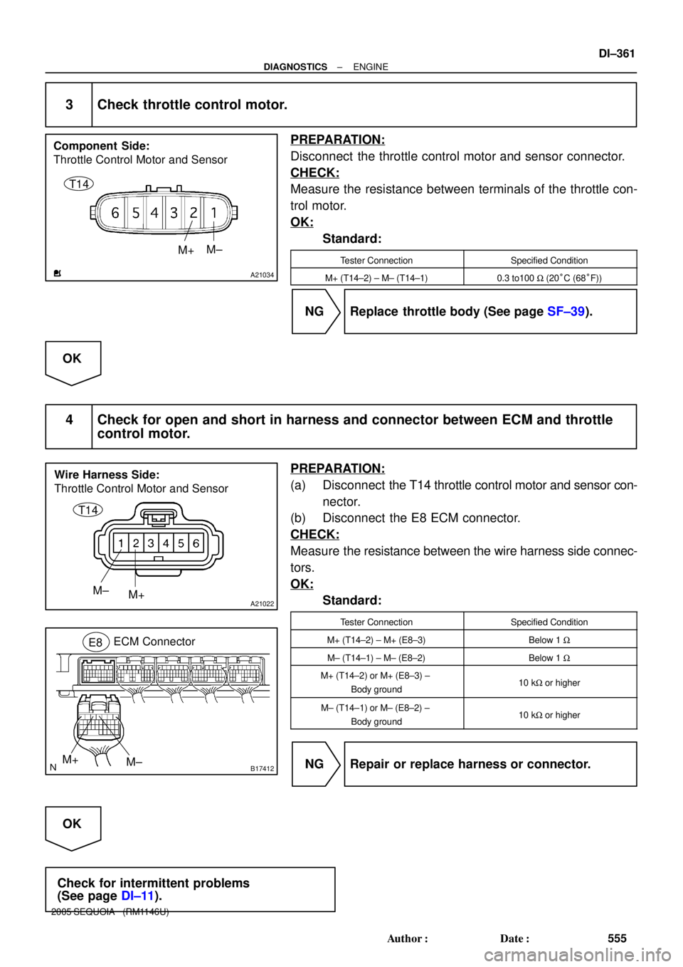
3 Check throttle control motor.
PREPARATION:
Disconnect the throttle control motor and sensor connector.
CHECK:
Measure the resistance between terminals of the throttle con-
trol motor.
OK:
Standard:
Tester ConnectionSpecified Condition
M+ (T14±2) ± M± (T14±1)0.3 to100 W (20°C (68°F))
NG Replace throttle body (See page SF±39).
OK
4 Check for open and short in harness and connector between ECM and throttle
control motor.
PREPARATION:
(a) Disconnect the T14 throttle control motor and sensor con-
nector.
(b) Disconnect the E8 ECM connector.
CHECK:
Measure the resistance between the wire harness side connec-
tors.
OK:
Standard:
Tester ConnectionSpecified Condition
M+ (T14±2) ± M+ (E8±3)Below 1 W
M± (T14±1) ± M± (E8±2)Below 1 W
M+ (T14±2) or M+ (E8±3) ±
Body ground10 kW or higher
M± (T14±1) or M± (E8±2) ±
Body ground10 kW or higher
NG Repair or replace harness or connector.
OK
Check for intermittent problems
(See page DI±11).
Page 567 of 4323

A21380
Engine Room J/B
ETCS
Fuse
B17411
+BM (+) E6
E4
E1 (±)
± DIAGNOSTICSENGINE
DI±365
559 Author�: Date�:
2005 SEQUOIA (RM1146U)
INSPECTION PROCEDURE
HINT:
Read freeze frame data using the hand-held tester. Freeze frame data records the engine conditions when
a malfunction is detected. When troubleshooting, freeze frame data can help determine if the vehicle was
running or stopped, if the engine was warmed up or not, if the air±fuel ratio was lean or rich, as well as other
data from the time when a malfunction occurred.
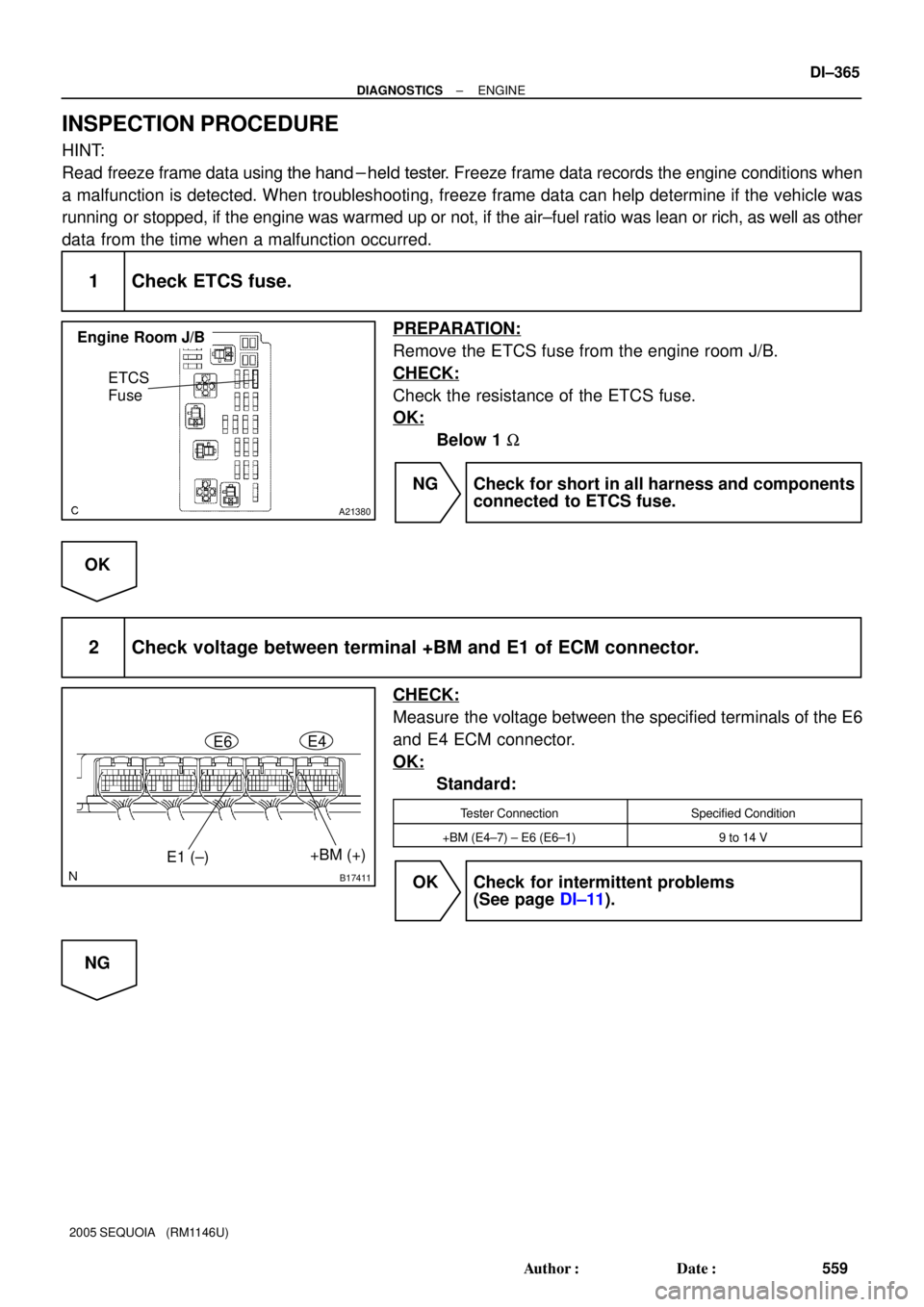
1 Check ETCS fuse.
PREPARATION:
Remove the ETCS fuse from the engine room J/B.
CHECK:
Check the resistance of the ETCS fuse.
OK:
Below 1 W
NG Check for short in all harness and components
connected to ETCS fuse.
OK
2 Check voltage between terminal +BM and E1 of ECM connector.
CHECK:
Measure the voltage between the specified terminals of the E6
and E4 ECM connector.
OK:
Standard:
Tester ConnectionSpecified Condition
+BM (E4±7) ± E6 (E6±1)9 to 14 V
OK Check for intermittent problems
(See page DI±11).
NG
Page 568 of 4323

A21380
Engine Room J/B
ETCS
Fuse
B17417
E4
+BM
DI±366
± DIAGNOSTICSENGINE
560 Author�: Date�:
2005 SEQUOIA (RM1146U)
3 Check for open or short in harness or connector between battery and ETCS fuse,
ETCS fuse and ECM.
PREPARATION:
(a) Remove the ETCS fuse from the engine room J/B.
(b) Disconnect the E4 ECM connector.
CHECK:
Measure the resistance of the wire harness side connector be-
tween the ETCS fuse and ECM.
OK:
Standard:
Tester ConnectionSpecified Condition
Engine Room J/B (ETCS fuse
terminal) ± +BM (E4±7)Below 1 W
Engine Room J/B (ETCS fuse
terminal) or +BM (E4±7) ±
Body ground
10 kW or higher
PREPARATION:
(a) Remove the ETCS fuse from the engine room J/B.
(b) Disconnect the battery positive terminal.
CHECK:
Measure the resistance of the wire harness side connector be-
tween the ETCS fuse and battery.
OK:
Standard:
Tester ConnectionSpecified Condition
Engine Room J/B (ETCS fuse
terminal) ± Battery positive terminalBelow 1 W
Engine Room J/B (ETCS fuse
terminal) or
Battery positive terminal ± Body ground
10 kW or higher
NG Repair or replace harness or connector.
OK
Check engine room J/B.