Page 952 of 4323
F19458
DI±750
± DIAGNOSTICSAIR SUSPENSION SYSTEM
944 Author�: Date�:
2005 SEQUOIA (RM1146U)
2 Inspect AIR SUS relay.
PREPARATION:
Remove the AIR SUS relay from the engine room R/B No. 2.
CHECK:
Check continuity between each terminal of the AIR SUS relay.
OK:
Tester connectionResistance
3 ± 510 kW or higher
3 ± 5
Below 1 W
(When battery voltage is applied to ter-
minals 1±2)
NG Replace AIR SUS relay.
OK
Page 953 of 4323
F16805
S25
Suspension Control ECU
Wire Harness View:
RC
F19460
Engine Room R/B No. 2:
AIR SUS
Relay Terminal
± DIAGNOSTICSAIR SUSPENSION SYSTEM
DI±751
945 Author�: Date�:
2005 SEQUOIA (RM1146U)
3 Check harness and connector (Engine room R/B ± Suspension control ECU,
Body ground).
PREPARATION:
Disconnect the ECU connector.
CHECK:
Check for an open or short circuit in the harness and the con-
nector between the AIR SUS relay terminal 1 of the engine
room R/B and terminal S25±5 (RC) of the suspension control
ECU.
OK:
There is no open or short in the wire harness.
CHECK:
Check for an open circuit in the harness and the connector be-
tween the AIR SUS relay terminal 2 of the engine room R/B and
body ground.
OK:
There is no open in the wire harness.
NG Repair or replace harness or connector.
OK
Replace suspension control ECU
(See page IN±35).
Page 954 of 4323

DTC C1742/42 Height Control Compressor Circuit
CIRCUIT DESCRIPTION
When the ºUPº side of the height control i")
DI±752
± DIAGNOSTICSAIR SUSPENSION SYSTEM
946 Author�: Date�:
2005 SEQUOIA (RM1146U)
DTC C1742/42 Height Control Compressor Circuit
CIRCUIT DESCRIPTION
When the ºUPº side of the height control is pressed, a signal is sent from terminal RC of the suspension con-
trol ECU to switch the AIR SUS relay ON. As a result, the relay contacts close and the compressor motor
turns on, producing compressed air.
The suspension control ECU detects the amount of current flow to the compressor motor by means of the
differences in potential at terminals RM+ and RM± of the suspension control ECU. In this way, the suspen-
sion control ECU monitors the compressor circuit for abnormalities.
DTC No.DTC Detecting ConditionTrouble Area
C1742/42
With the AIR SUS relay activated, a lock, open or short signal
of the height control compressor motor is detected for 4 sec. or
more.�Height control compressor assy
�Height control compressor circuit
�Suspension control ECU
HINT:
Once the ECU stores DTC C1742/42 in the memory, the vehicle height control is not carried out until the
normal signal is input to the ECU from the compressor motor. However, the control automatically resumes
approx. 70 min. after the ignition switch is turned ON.
DIDDU±01
Page 956 of 4323
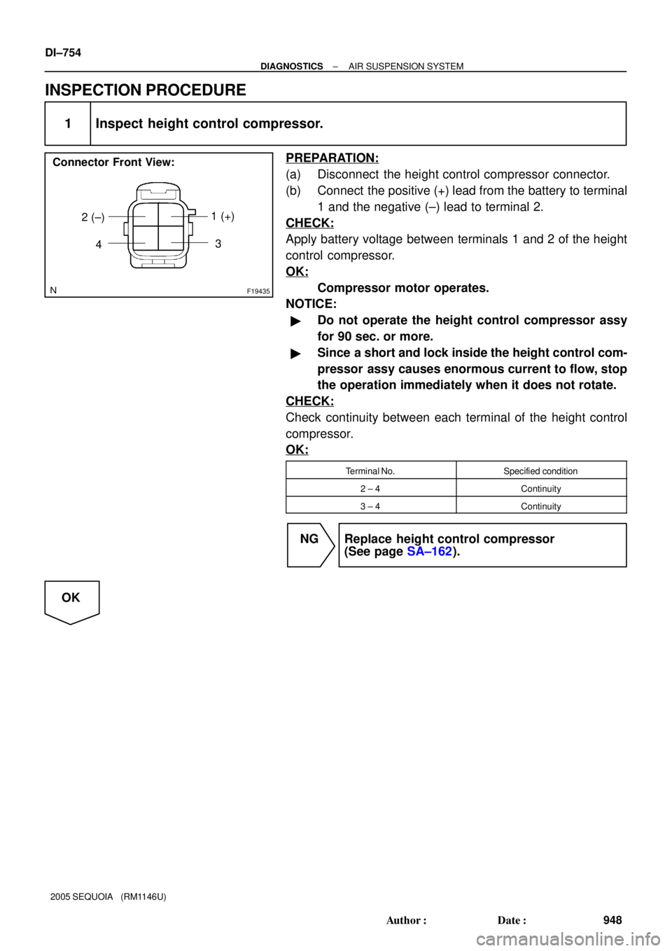
F19435
1 (+)
2 (±)
Connector Front View:
43
DI±754
± DIAGNOSTICSAIR SUSPENSION SYSTEM
948 Author�: Date�:
2005 SEQUOIA (RM1146U)
INSPECTION PROCEDURE
1 Inspect height control compressor.
PREPARATION:
(a) Disconnect the height control compressor connector.
(b) Connect the positive (+) lead from the battery to terminal
1 and the negative (±) lead to terminal 2.
CHECK:
Apply battery voltage between terminals 1 and 2 of the height
control compressor.
OK:
Compressor motor operates.
NOTICE:
�Do not operate the height control compressor assy
for 90 sec. or more.
�Since a short and lock inside the height control com-
pressor assy causes enormous current to flow, stop
the operation immediately when it does not rotate.
CHECK:
Check continuity between each terminal of the height control
compressor.
OK:
Terminal No.Specified condition
2 ± 4Continuity
3 ± 4Continuity
NG Replace height control compressor
(See page SA±162).
OK
Page 957 of 4323
F16805
Suspension Control ECU
Wire Harness View:
S25
RM+
RM±
F19461
Height Control Compressor
Connector Front View:
H13
± DIAGNOSTICSAIR SUSPENSION SYSTEM
DI±755
949 Author�: Date�:
2005 SEQUOIA (RM1146U)
2 Check harness and connector (height control compressor ± Suspension control
ECU).
PREPARATION:
Disconnect the ECU connector.
CHECK:
Check for an open or short circuit in the harness and the con-
nector between terminals 3 and 4 of the height control compres-
sor and terminals S25±20 (RM+) and S25±21 (RM±) of the sus-
pension control ECU.
OK:
There is no open or short in the wire harness.
NG Repair or replace harness or connector.
OK
Page 961 of 4323

3")
F19437
Height Control Valve
Connector Front View:
32 1
F19457
Height Control Compressor
Connector Front View:
± DIAGNOSTICSAIR SUSPENSION SYSTEM
DI±759
953 Author�: Date�:
2005 SEQUOIA (RM1146U)
3 Inspect height control valve (Gate solenoid valve, Leveling solenoid valve) or
height control compressor (Exhaust solenoid valve).
When using hand±held tester:
PREPARATION:
(a) Connect the hand±held tester to the DLC3.
(b) Turn the ignition switch ON, and push the hand±held tester main switch ON.
(c) Select the item ºLEVEL SOL REARº, ºGATE SOL REARº in the ACTIVE TEST, and operate it with the
hand±held tester.
AIR SUSPENSION:
ItemVehicle Condition / Test DetailsDiagnostic Note
LEVEL SOL REARTurn leveling solenoid valve / ON or OFFOperation sound of solenoid (clicking sound) can
be heard
GATE SOL REARTurn gate solenoid valve / ON or OFFOperation sound of solenoid (clicking sound) can
be heard
HINT:
The exhaust solenoid valve cannot be tested in ACTIVE TEST.
CHECK:
(a) Check whether the solenoid makes a sound.
(b) Check whether the height control solenoid valve has continuity (will vibrate).
OK:
The solenoid makes a sound, and the height control solenoid valve has continuity. (It will vi-
brate.)
When not using hand±held tester:
PREPARATION:
Disconnect the valve connector.
CHECK:
Check the operating sound of the valves when battery positive
voltage is applied to the terminals as shown below.
Solenoid valveBattery positiveBattery negative
Height control valve
(Gate solenoid valve)12
Height control valve
(Leveling solenoid valve)32
Height control compressor
(Exhaust solenoid valve)12
OK:
It make an operating sound (click).
HINT:
�When a malfunction is found in the gate solenoid valve,
replace the leveling valve and the height control valve.
�When a malfunction is found in the exhaust solenoid
valve, replace the height control compressor assy.
Page 965 of 4323
F19445
Engine Room R/B No. 2
F10
Fusible Link BlockSuspension Control
ECU
AIR SUS No. 2
2
1
22 W
AIR SUS
9ALT
5B
Battery
IFJ12
J/C
AW±B22
S25
GND 24
S25
25
S25
BAT B J/C
B
J37
B
J37 C
J38 V
IA55
VV
V
± DIAGNOSTICSAIR SUSPENSION SYSTEM
DI±763
957 Author�: Date�:
2005 SEQUOIA (RM1146U)
DTC C1774/74 Power Source Circuit
CIRCUIT DESCRIPTION
�This circuit provides power to operate the suspension control ECU.
�The suspension control ECU, controlling the air suspension system, is activated when the ignition
switch is turned ON. The main relay inside the ECU is activated after 2 seconds and the system is oper-
ated by +B power source.
DTC No.DTC Detecting ConditionTrouble Area
C1774/74The terminal B or BAT voltage is below 10 V or above 16 V for
0.5 seconds.�Battery
�Power source circuit
�Suspension control ECU
WIRING DIAGRAM
DIDE3±01
Page 966 of 4323

INSPECTION PROCEDURE
1 Inspect battery voltage.
CHECK:
Check the battery voltage.
OK:
Voltage: 11 to 14 V
NG Re")
DI±764
± DIAGNOSTICSAIR SUSPENSION SYSTEM
958 Author�: Date�:
2005 SEQUOIA (RM1146U)
INSPECTION PROCEDURE
1 Inspect battery voltage.
CHECK:
Check the battery voltage.
OK:
Voltage: 11 to 14 V
NG Replace battery.
OK
HINT:
Start the inspection from step 2 when using the hand±held tester, and start from step 3 when not using the
hand±held tester.
2 Read value of the hand±held tester.
PREPARATION:
(a) Connect the hand±held tester to the DLC3.
(b) Turn the ignition switch ON, and push the hand±held tester main switch ON.
(c) Select the item ºPOWER VOLTAGEº in the DATA LIST, and read its value displayed on the hand±held
tester.
AIR SUSPENSION:
ItemMeasurement Item / Range (Dis-
play)Normal ConditionDiagnostic Note
POWER VOLTAGE+B power source voltage / min.: 0
V, max.: 25.5 VActual battery power supply volt-
age: 10 to 14 V±
CHECK:
Check the battery positive voltage.
OK:
Actual battery power supply voltage: 10 to 14 V
RESULT:
NGA
OK (When troubleshooting according to the PROBLEM SYMPTOMS TABLE)B
OK (When troubleshooting according to the DTC chart)C
B Proceed to next circuit inspection shown in
problem symptoms table (See page DI±716).
C Check for intermittent problems.
HINT:
Check the connector and terminal (See page IN±24).