Page 967 of 4323
F16805
S25
BAT
B
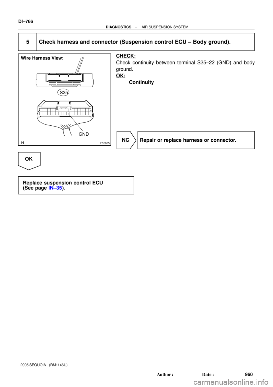
Wire Harness View:
± DIAGNOSTICSAIR SUSPENSION SYSTEM
DI±765
959 Author�: Date�:
2005 SEQUOIA (RM1146U)
A
3 Inspect fuse (AIR SUS No. 2).
PREPARATION:
Remove the AIR SUS No. 2 fuse from the engine room R/B.
CHECK:
Check continuity of the AIR SUS No. 2 fuse.
OK:
Continuity
NG Inspect for short circuit in all harness and com-
ponents connected to AIR SUS No. 2 fuse.
OK
4 Inspect suspension control ECU.
PREPARATION:
Disconnect the ECU connector.
CHECK:
Measure the voltage between terminal S25±24 (B) of the sus-
pension control ECU connector and body ground and between
terminal S25±25 (BAT) and body ground.
OK:
Voltage: 10 to 14 V
NG Repair or replace harness or connector.
OK
Page 968 of 4323
F16805
Wire Harness View:
GND S25
DI±766
± DIAGNOSTICSAIR SUSPENSION SYSTEM
960 Author�: Date�:
2005 SEQUOIA (RM1146U)
5 Check harness and connector (Suspension control ECU ± Body ground).
CHECK:
Check continuity between terminal S25±22 (GND) and body
ground.
OK:
Continuity
NG Repair or replace harness or connector.
OK
Replace suspension control ECU
(See page IN±35).
Page 969 of 4323
F19446
W
41G±Y1
4A11
4AG±Y27
S25 STP
BatteryB ALT
85 W 1
1L STOP 2
1FS14
Stop Light Switch
Sub J/B No. 4Suspension Control
ECU
Instrument Panel J/BF10
Fusible Link Block
1L
± DIAGNOSTICSAIR SUSPENSION SYSTEM
DI±767
961 Author�: Date�:
2005 SEQUOIA (RM1146U)
DTC C1782/82 Stop Light Switch Circuit (Test Diagnosis)
CIRCUIT DESCRIPTION
When the brake pedal is depressed, the stop light comes on and the signal is input to the STP terminal of
the suspension control ECU.
HINT:
This DTC is output only when the sensor signal check is done.
DTC No.DTC Detecting ConditionTrouble Area
C1782/82The signal from the stop light switch assy does not change.
�Stop light switch assy
�Stop light switch circuit
�Suspension control ECU
WIRING DIAGRAM
DIDE7±01
Page 970 of 4323
F16805
Wire Harness View:
S25
STP
DI±768
± DIAGNOSTICSAIR SUSPENSION SYSTEM
962 Author�: Date�:
2005 SEQUOIA (RM1146U)
INSPECTION PROCEDURE
1 Inspect stop light.
CHECK:
Check that the stop light comes on when the brake pedal is depressed and goes off when the brake pedal
is released.
OK:
Stop light operates normally.
NG Go to step 3.
OK
2 Inspect suspension control ECU.
PREPARATION:
Disconnect the ECU connector.
CHECK:
Measure the voltage between terminal S25±27 (STP) of the
suspension control ECU and body ground when the stop light
switch is ON and OFF.
OK:
Switch conditionSpecified condition
Brake pedal depressed (ON)10 to 14 V
Brake pedal released (OFF)Below 1 V
NG Repair or replace harness connector.
OK
Replace suspension control ECU
(See page IN±35).
Page 971 of 4323
I21525
Free Pushed in
F16805
Wire Harness View:
S25
STP
± DIAGNOSTICSAIR SUSPENSION SYSTEM
DI±769
963 Author�: Date�:
2005 SEQUOIA (RM1146U)
3 Inspect stop light switch assy.
PREPARATION:
Disconnect the stop light switch assy connector.
CHECK:
Check resistance between terminals 1 and 4 of the stop light
switch assy.
OK:
Switch conditionTester connectionSpecified condition
Switch pin free1 ± 4Below 1 W
Switch pin pushed in1 ± 410 kW or higher
NG Replace stop light switch assy.
OK
4 Inspect suspension control ECU.
PREPARATION:
Disconnect the ECU connector.
CHECK:
Measure the voltage between terminal S25±27 (STP) of the
suspension control ECU and body ground when the stop lamp
switch is ON and OFF.
OK:
Switch conditionSpecified condition
Brake pedal depressed (ON)10 to 14 V
Brake pedal released (OFF)Below 1 V
NG Repair or replace harness connector.
OK
Replace suspension control ECU
(See page IN±35).
Page 972 of 4323
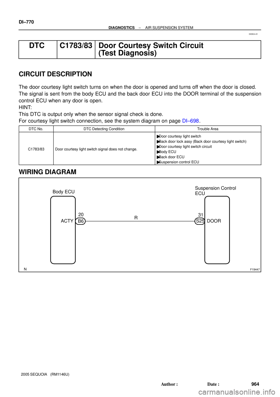
F19447
Body ECUSuspension Control
ECU
ACTY20
B631
S25 DOOR R DI±770
± DIAGNOSTICSAIR SUSPENSION SYSTEM
964 Author�: Date�:
2005 SEQUOIA (RM1146U)
DTC C1783/83 Door Courtesy Switch Circuit
(Test Diagnosis)
CIRCUIT DESCRIPTION
The door courtesy light switch turns on when the door is opened and turns off when the door is closed.
The signal is sent from the body ECU and the back door ECU into the DOOR terminal of the suspension
control ECU when any door is open.
HINT:
This DTC is output only when the sensor signal check is done.
For courtesy light switch connection, see the system diagram on page DI±698.
DTC No.DTC Detecting ConditionTrouble Area
C1783/83Door courtesy light switch signal does not change.
�Door courtesy light switch
�Back door lock assy (Back door courtesy light switch)
�Door courtesy light switch circuit
�Body ECU
�Back door ECU
�Suspension control ECU
WIRING DIAGRAM
DIDEA±01
Page 975 of 4323
I27702
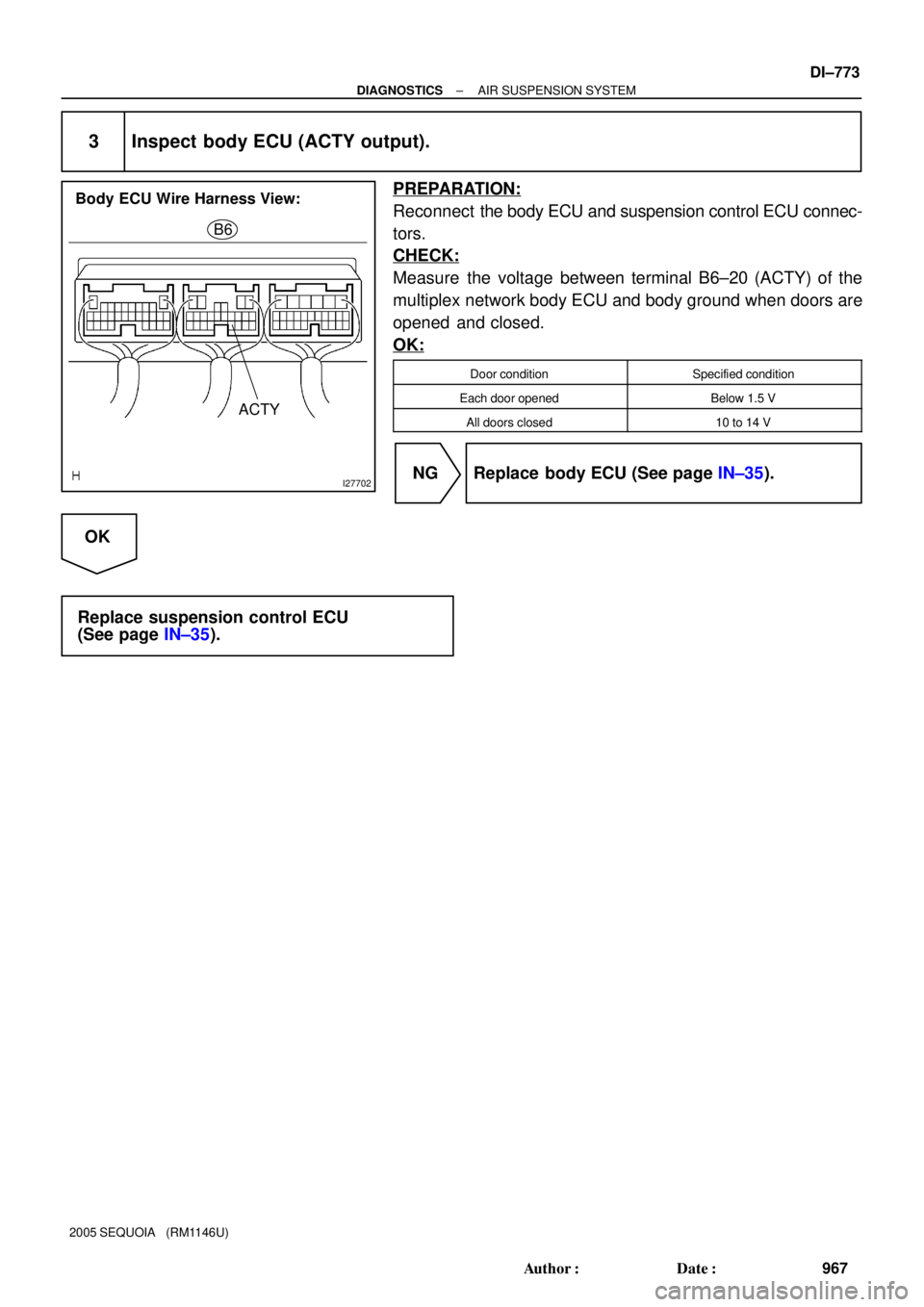
Body ECU Wire Harness View:
B6
ACTY
± DIAGNOSTICSAIR SUSPENSION SYSTEM
DI±773
967 Author�: Date�:
2005 SEQUOIA (RM1146U)
3 Inspect body ECU (ACTY output).
PREPARATION:
Reconnect the body ECU and suspension control ECU connec-
tors.
CHECK:
Measure the voltage between terminal B6±20 (ACTY) of the
multiplex network body ECU and body ground when doors are
opened and closed.
OK:
Door conditionSpecified condition
Each door openedBelow 1.5 V
All doors closed10 to 14 V
NG Replace body ECU (See page IN±35).
OK
Replace suspension control ECU
(See page IN±35).
Page 978 of 4323
F19433
3
UP Button
DOWN Button
Height Control
Switch
12 45
DI±776
± DIAGNOSTICSAIR SUSPENSION SYSTEM
970 Author�: Date�:
2005 SEQUOIA (RM1146U)
2 Inspect height control switch.
PREPARATION:
Remove the height control switch connector.
CHECK:
Check continuity between each terminal of the height control
switch when the height control switch ºUPº or ºDOWNº button
is pressed.
OK:
Tester connectionSwitch conditionSpecification
ºUPº button2 ± 3Continuity
ºDOWNº button2 ± 3No continuity
ºUPº button2 ± 4No continuity
ºDOWNº button2 ± 4Continuity
NG Replace height control switch.
OK