Page 2591 of 4323

VALVE CLEARANCE
INSPECTION
HINT:
Inspect and adjust the valve clearance when the engine")
EM0KS±09
A23300
A23301
EM±4
± ENGINE MECHANICALVALVE CLEARANCE
2583 Author�: Date�:
2005 SEQUOIA (RM1146U)
VALVE CLEARANCE
INSPECTION
HINT:
Inspect and adjust the valve clearance when the engine is cold.
1. REMOVE BATTERY CLAMP COVER
2. REMOVE THROTTLE BODY COVER
3. REMOVE AIR CLEANER AND INTAKE AIR CONNEC-
TOR ASSEMBLY
4. REMOVE NO.3 TIMING BELT COVERS
(See page EM±16)
5. REMOVE IGNITION COILS (See page IG±5)
6. REMOVE RH CYLINDER HEAD COVER
Remove the 9 bolts, seal washers and cylinder head cover.
7. REMOVE LH CYLINDER HEAD COVER
(a) Remove the oil dipstick for the transmission.
(b) Disconnect the PCV hose.
(c) Disconnect the engine wire clamp from the wire bracket
on the cylinder head cover.
(d) Remove the 9 bolts, 9 seal washers and cylinder head
cover.
8. SET NO.1 CYLINDER TO TDC/COMPRESSION
(a) Turn the crankshaft pulley, and align its groove with timing
mark º0º of the No.1 timing belt cover.
(b) Check that the timing marks of the camshaft timing pul-
leys and timing belt rear plates are aligned.
If not, turn the crankshaft 1 revolution (360°) and align the mark
as above.
Page 2593 of 4323

10. ADJUST VALVE CLEARANCE
(a) Remove the timing belt. (See page EM±16)
(b) Remove the camshafts. (See p")
A02213
EM±6
± ENGINE MECHANICALVALVE CLEARANCE
2585 Author�: Date�:
2005 SEQUOIA (RM1146U)
10. ADJUST VALVE CLEARANCE
(a) Remove the timing belt. (See page EM±16)
(b) Remove the camshafts. (See page EM±36)
(c) Remove the valve lifter and adjusting shim.
(d) Determine the replacement adjusting shim size according
to these Formula or Charts:
(1) Using a micrometer, measure the thickness of the
removed shim.
(2) Calculate the thickness of a new shim so that the
valve clearance comes within the specified value.
T ........... Thickness of removed shim
A ........... Measured valve clearance
N ........... Thickness of new shim
Intake: N = T + (A ± 0.20 mm (0.008 in.))
Exhaust: N = T + (A ± 0.30 mm (0.012 in.))
(3) Select a new shim with thickness as close as pos-
sible to the calculated value.
HINT:
Shims are available in 41 increments of 0.020 mm (0.0008 in.),
from 2.00 mm (0.0787 in.) to 2.80 mm (0.1102 in.).
(e) Place a new adjusting shim on the valve.
(f) Place the valve lifter.
(g) Reinstall the camshafts. (See page EM±60)
(h) Reinstall the timing belt. (See page EM±23)
(i) Recheck the valve clearance.
11. REINSTALL CYLINDER HEAD COVERS
12. REINSTALL IGNITION COILS
13. REINSTALL NO.3 TIMING BELT COVERS
(See page EM±23)
14. REINSTALL AIR CLEANER AND INTAKE AIR
CONNECTOR ASSEMBLY
15. REINSTALL THROTTLE BODY COVER
16. REINSTALL BATTERY CLAMP COVER
Page 2596 of 4323
EM0KT±11
D13872
Hand±Held Tester
DLC3
CAN VIM
A08769
A23394
TC
SST
DLC3
CG
± ENGINE MECHANICALIGNITION TIMING
EM±9
2588 Author�: Date�:
2005 SEQUOIA (RM1146U)
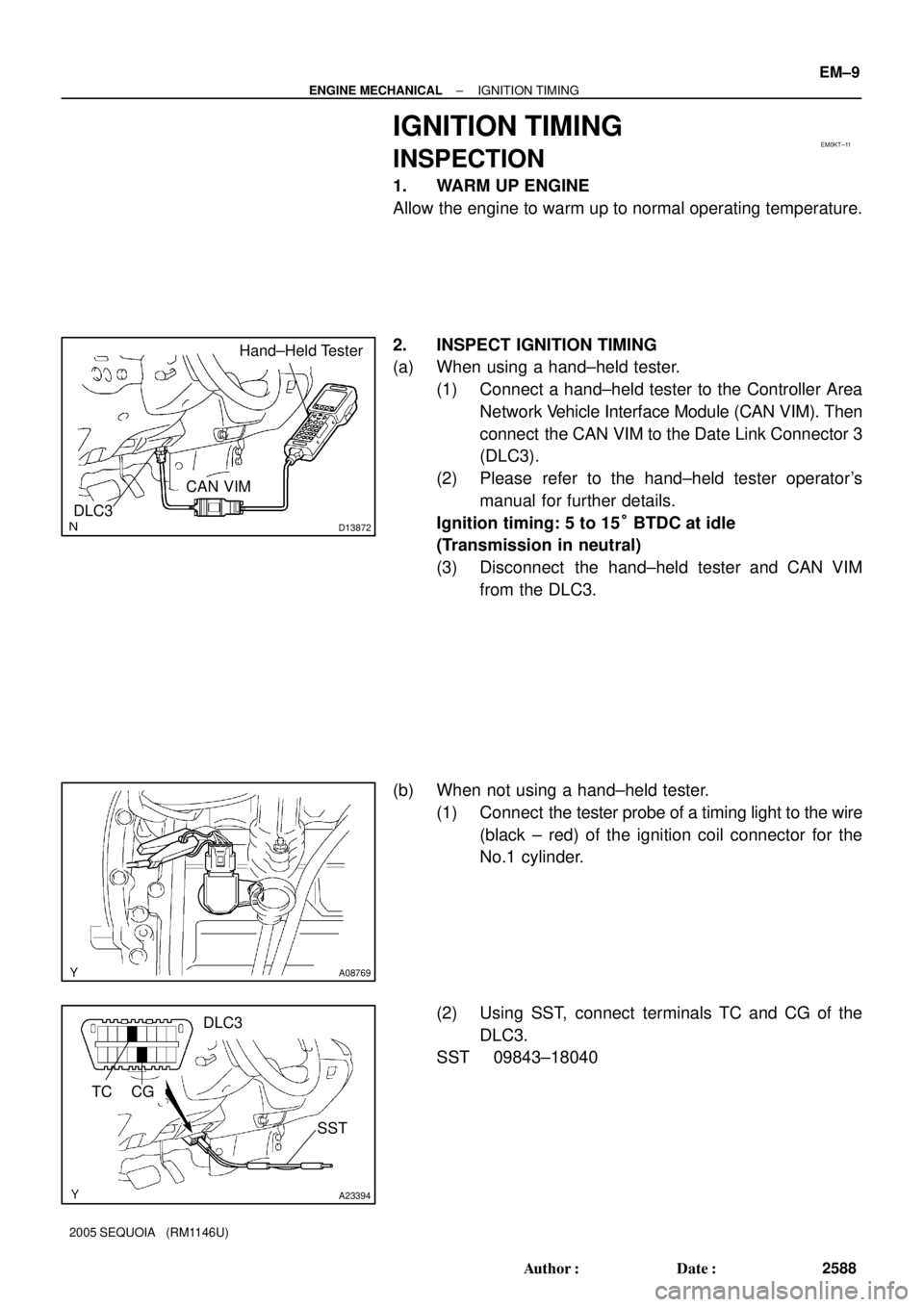
IGNITION TIMING
INSPECTION
1. WARM UP ENGINE
Allow the engine to warm up to normal operating temperature.
2. INSPECT IGNITION TIMING
(a) When using a hand±held tester.
(1) Connect a hand±held tester to the Controller Area
Network Vehicle Interface Module (CAN VIM). Then
connect the CAN VIM to the Date Link Connector 3
(DLC3).
(2) Please refer to the hand±held tester operator's
manual for further details.
Ignition timing: 5 to 15° BTDC at idle
(Transmission in neutral)
(3) Disconnect the hand±held tester and CAN VIM
from the DLC3.
(b) When not using a hand±held tester.
(1) Connect the tester probe of a timing light to the wire
(black ± red) of the ignition coil connector for the
No.1 cylinder.
(2) Using SST, connect terminals TC and CG of the
DLC3.
SST 09843±18040
Page 2600 of 4323
EM0KV±13
A19404
PS Air Hose
Intake Air ConnectorRadiator Assembly
N´m (kgf´cm, ft´lbf) : Specified torqueDrive BeltA/C Compressor
Connector
A/T Oil Cooler Hose
Fan and Fluid Coupling
Assembly
Fan Pulley
49 (500, 36)
x 4
29 (296, 21)
Throttle Body Cover
MAF Meter Wire
Engine Under Cover (4WD)2WDEngine Under Cover
PS PumpNo. 2 Fan Shroud
Vacuum Hose
PCV Hose
Clip
17 (175, 13)
12 (122, 9)
A/C Compressor
A/C Suction Hose
17 (175, 13)
x 5
29 (296, 21)
29 (296, 21)
± ENGINE MECHANICALTIMING BELT
EM±13
2592 Author�: Date�:
2005 SEQUOIA (RM1146U)
TIMING BELT
COMPONENTS
Page 2601 of 4323
A23302
RH No.3 Timing Belt Cover
No.2 Timing
Belt Cover
LH No.3 Timing Belt Cover Drive Belt Idler Pulley
Camshaft Position
Sensor ConnectorCover Plate
Oil Cooler Pipe Engine Wire
7.5 (76, 66 in.´lbf)
16 (160, 12)
7.5 (76, 66 in.´lbf)
N´m (kgf´cm, ft´lbf) : Specified torque
Wire Grommet
39 (400, 29)
A23303
Timing BeltLH Camshaft Timing Pulley
Timing Belt Tensioner
Dust Boot
245 (2,500, 181)
16 (160, 12)
32 (330, 24)
RH Camshaft Timing Pulley
26 (270, 19)Fan Bracket
N´m (kgf´cm, ft´lbf) : Specified torque
8.1 (83, 72 in.´lbf)
EM±14
± ENGINE MECHANICALTIMING BELT
2593 Author�: Date�:
2005 SEQUOIA (RM1146U)
Page 2604 of 4323
A04330
A04455
A23305
A23306
SST
± ENGINE MECHANICALTIMING BELT
EM±17
2596 Author�: Date�:
2005 SEQUOIA (RM1146U)
(g) Remove the LH No.3 timing belt cover.
(h) Remove the bolt, nut and oil cooler pipe.
11. REMOVE NO.2 TIMING BELT COVER
Remove the 2 bolts and No.2 timing belt cover.
12. DISCONNECT A/C COMPRESSOR FROM ENGINE
(See page EM±79)
13. REMOVE FAN BRACKET
Remove the 2 bolts, 2 nuts and fan bracket.
14. IF RE±USING TIMING BELT, CHECK INSTALLATION
MARKS ON TIMING BELT
Check that there are 3 installation marks on the timing belt by
turning the crankshaft pulley as shown in the illustration.
HINT:
If the installation marks have disappeared, place a new installa-
tion mark on the timing belt before removing each part.
15. LOOSEN CRANKSHAFT PULLEY BOLT
Using SST, loosen the pulley bolt.
SST 09213±70011 (90105±08076), 09330±00021
Page 2608 of 4323

INSPECTION
1. INSPECT TIMING BELT
NOTICE:
�Do not bend, twist or turn the timin")
EM0KX±07
EM3336
NO !
P20079
P20633
± ENGINE MECHANICALTIMING BELT
EM±21
2600 Author�: Date�:
2005 SEQUOIA (RM1146U)
INSPECTION
1. INSPECT TIMING BELT
NOTICE:
�Do not bend, twist or turn the timing belt inside out.
�Do not allow the timing belt to come into contact with
oil, water or steam.
�Do not utilize timing belt tension when installing or re-
moving the mount bolt of the camshaft timing pulley.
If there is any defect, as shown in the illustration, check these
points:
(a) Premature parting
�Check for proper installation.
�Check the timing cover gasket for damage and
proper installation.
(b) If the belt teeth are cracked or damaged, check to see if
either camshaft is locked.
(c) If there is noticeable wear or cracks on the belt face,
check to see if there are nicks on the side of the idler
pulley lock and water pump.
(d) If there is wear or damage on even one side of the belt,
check the belt guide and the alignment of each pulley.
(e) If there is noticeable wear on the belt teeth, check timing
cover for damage and for foreign material on the pulley
teeth.
If necessary, replace the timing belt.
2. INSPECT IDLER PULLEYS
(a) Visually check the seal portion of the idler pulley for oil
leakage.
If leakage is found, replace the idler pulley.
(b) Check that the idler pulley turns smoothly.
If necessary, replace the idler pulley.
3. INSPECT TIMING BELT TENSIONER
(a) Visually check the seal portion of the tensioner for oil leak-
age.
HINT:
If there is only the faintest trace of oil on the seal on the push
rod side, the tensioner is all right.
If leakage is found, replace the tensioner.
Page 2610 of 4323

INSTALLATION
1. INSTALL CRANKSHAFT TIMING PULLEY
(a) Align the timing pul")
EM1WY±01
A04446
SST
Inward
A04447
A04342
± ENGINE MECHANICALTIMING BELT
EM±23
2602 Author�: Date�:
2005 SEQUOIA (RM1146U)
INSTALLATION
1. INSTALL CRANKSHAFT TIMING PULLEY
(a) Align the timing pulley set key with the key groove of the
pulley.
(b) Using SST and a hammer, tap in the timing pulley, facing
the flange side inward.
SST 09223±46011
2. INSTALL NO.1 IDLER PULLEY AND NO.2 IDLER
PULLEY
(a) Apply adhesive 2 or 3 threads of the pivot bolt.
Adhesive:
Part No. 08833±00080, THREE BOND 1344,
LOCTITE 242 or equivalent
(b) Using a 10 mm hexagon wrench, install the plate washer
and No.1 idler pulley with the pivot bolt.
Torque: 34.5 N´m (350 kgf´cm, 25 ft´lbf)
(c) Install the No.2 idler pulley with the bolt.
Torque: 34.5 N´m (350 kgf´cm, 25 ft´lbf)
(d) Check that the No.1 and No.2 idler pulleys moves
smoothly.
3. TEMPORARILY INSTALL TIMING BELT
NOTICE:
The engine should be cold.
(a) Remove any oil or water on the crankshaft pulley, oil
pump pulley, water pump pulley, No.1 idler pulley and
No.2 idler pulley, and keep them clean.
NOTICE:
Only wipe the pulleys; do not use any cleansing agent.
(b) Align the installation mark on the timing belt with the tim-
ing mark of the crankshaft timing pulley.
(c) Install the timing belt on the crankshaft timing pulley, No.1
idler pulley and No.2 idler pulley.
4. INSTALL TIMING BELT COVER SPACER
(a) Install the gasket to the cover spacer.
(b) Install the cover spacer.
 : Specified torqueDrive BeltA/C Compressor
Connector
A/T Oil Cooler Hose
Fan and Fluid Coupling
Assembly
Fan")