Page 2640 of 4323
A04099A A
A04084
A23348
± ENGINE MECHANICALCYLINDER HEAD
EM±53
2632 Author�: Date�:
2005 SEQUOIA (RM1146U)
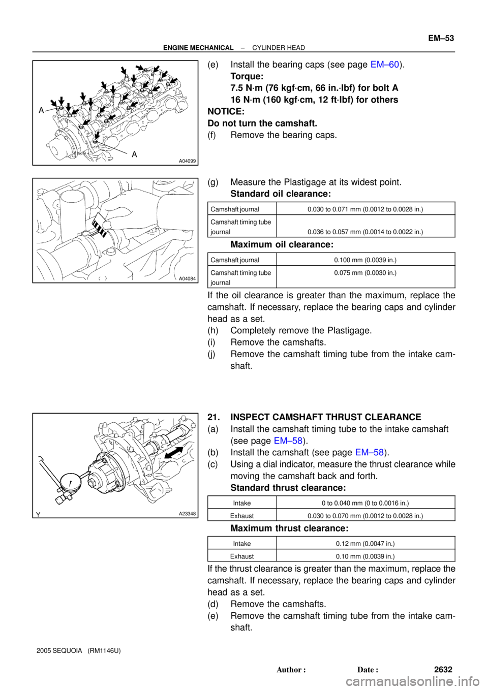
(e) Install the bearing caps (see page EM±60).
Torque:
7.5 N´m (76 kgf´cm, 66 in.´lbf) for bolt A
16 N´m (160 kgf´cm, 12 ft´lbf) for others
NOTICE:
Do not turn the camshaft.
(f) Remove the bearing caps.
(g) Measure the Plastigage at its widest point.
Standard oil clearance:
Camshaft journal0.030 to 0.071 mm (0.0012 to 0.0028 in.)
Camshaft timing tube
journal
0.036 to 0.057 mm (0.0014 to 0.0022 in.)
Maximum oil clearance:
Camshaft journal0.100 mm (0.0039 in.)
Camshaft timing tube
journal0.075 mm (0.0030 in.)
If the oil clearance is greater than the maximum, replace the
camshaft. If necessary, replace the bearing caps and cylinder
head as a set.
(h) Completely remove the Plastigage.
(i) Remove the camshafts.
(j) Remove the camshaft timing tube from the intake cam-
shaft.
21. INSPECT CAMSHAFT THRUST CLEARANCE
(a) Install the camshaft timing tube to the intake camshaft
(see page EM±58).
(b) Install the camshaft (see page EM±58).
(c) Using a dial indicator, measure the thrust clearance while
moving the camshaft back and forth.
Standard thrust clearance:
Intake0 to 0.040 mm (0 to 0.0016 in.)
Exhaust0.030 to 0.070 mm (0.0012 to 0.0028 in.)
Maximum thrust clearance:
Intake0.12 mm (0.0047 in.)
Exhaust0.10 mm (0.0039 in.)
If the thrust clearance is greater than the maximum, replace the
camshaft. If necessary, replace the bearing caps and cylinder
head as a set.
(d) Remove the camshafts.
(e) Remove the camshaft timing tube from the intake cam-
shaft.
Page 2641 of 4323
A04082
A03209
A03201
12.3 to 12.7 mm
EM±54
± ENGINE MECHANICALCYLINDER HEAD
2633 Author�: Date�:
2005 SEQUOIA (RM1146U)
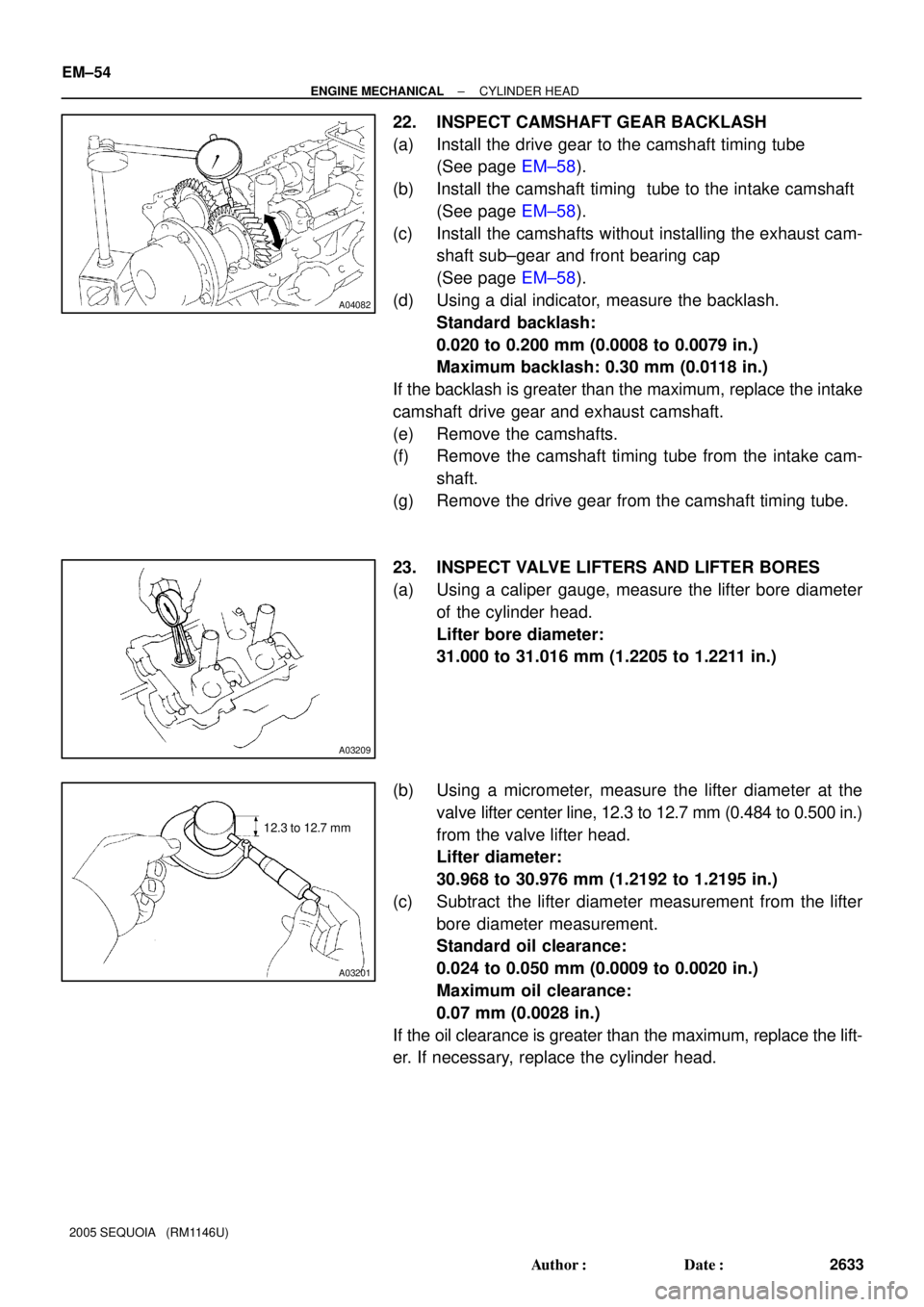
22. INSPECT CAMSHAFT GEAR BACKLASH
(a) Install the drive gear to the camshaft timing tube
(See page EM±58).
(b) Install the camshaft timing tube to the intake camshaft
(See page EM±58).
(c) Install the camshafts without installing the exhaust cam-
shaft sub±gear and front bearing cap
(See page EM±58).
(d) Using a dial indicator, measure the backlash.
Standard backlash:
0.020 to 0.200 mm (0.0008 to 0.0079 in.)
Maximum backlash: 0.30 mm (0.0118 in.)
If the backlash is greater than the maximum, replace the intake
camshaft drive gear and exhaust camshaft.
(e) Remove the camshafts.
(f) Remove the camshaft timing tube from the intake cam-
shaft.
(g) Remove the drive gear from the camshaft timing tube.
23. INSPECT VALVE LIFTERS AND LIFTER BORES
(a) Using a caliper gauge, measure the lifter bore diameter
of the cylinder head.
Lifter bore diameter:
31.000 to 31.016 mm (1.2205 to 1.2211 in.)
(b) Using a micrometer, measure the lifter diameter at the
valve lifter center line, 12.3 to 12.7 mm (0.484 to 0.500 in.)
from the valve lifter head.
Lifter diameter:
30.968 to 30.976 mm (1.2192 to 1.2195 in.)
(c) Subtract the lifter diameter measurement from the lifter
bore diameter measurement.
Standard oil clearance:
0.024 to 0.050 mm (0.0009 to 0.0020 in.)
Maximum oil clearance:
0.07 mm (0.0028 in.)
If the oil clearance is greater than the maximum, replace the lift-
er. If necessary, replace the cylinder head.
Page 2645 of 4323
EM0L4±09
P08885
Adhesive
15 mm (0.59 in.)
A03212
Protrusion
A05710
SST
A05711
(1)(2)(3)(4)
EM±58
± ENGINE MECHANICALCYLINDER HEAD
2637 Author�: Date�:
2005 SEQUOIA (RM1146U)
REASSEMBLY
HINT:
�Thoroughly clean all parts to be assembled.
�Before installing the parts, apply fresh engine oil to all slid-
ing and rotating surfaces.
�Replace all gaskets and oil seals with new ones.
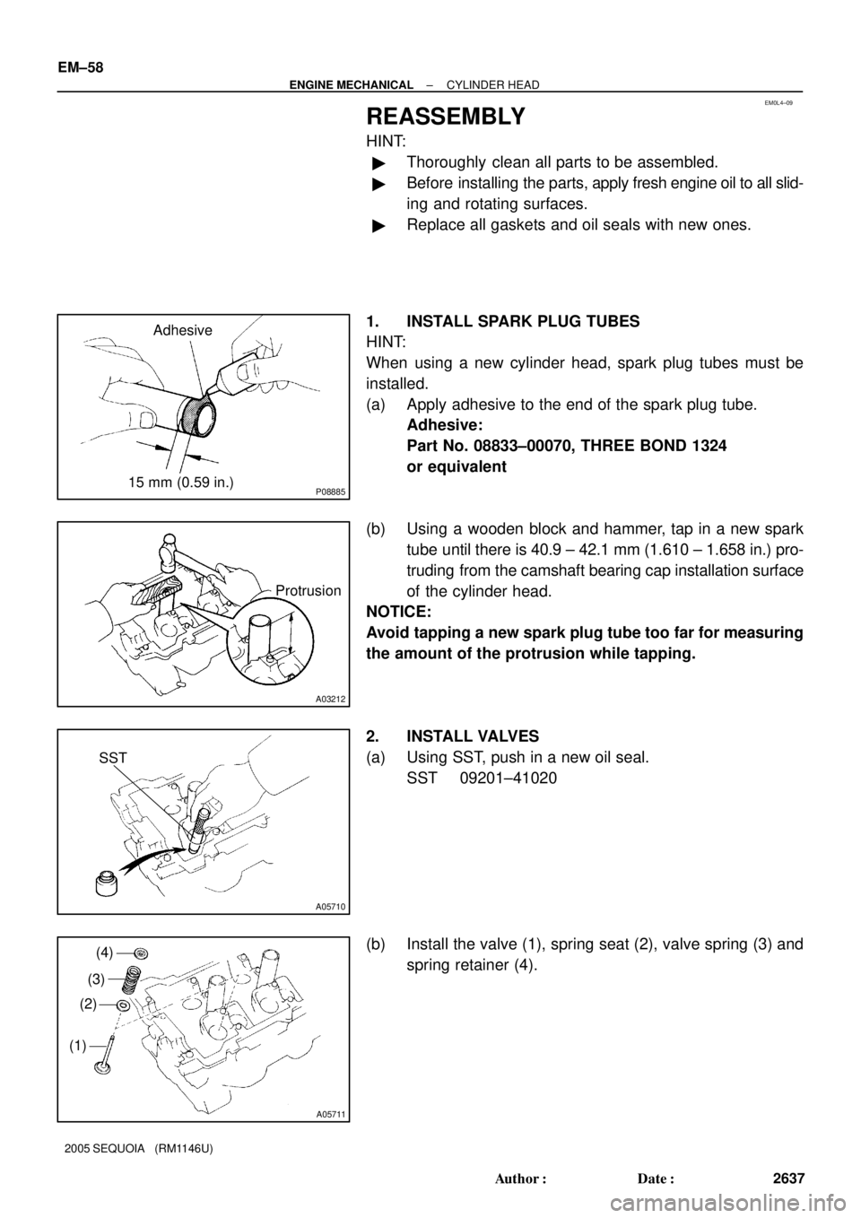
1. INSTALL SPARK PLUG TUBES
HINT:
When using a new cylinder head, spark plug tubes must be
installed.
(a) Apply adhesive to the end of the spark plug tube.
Adhesive:
Part No. 08833±00070, THREE BOND 1324
or equivalent
(b) Using a wooden block and hammer, tap in a new spark
tube until there is 40.9 ± 42.1 mm (1.610 ± 1.658 in.) pro-
truding from the camshaft bearing cap installation surface
of the cylinder head.
NOTICE:
Avoid tapping a new spark plug tube too far for measuring
the amount of the protrusion while tapping.
2. INSTALL VALVES
(a) Using SST, push in a new oil seal.
SST 09201±41020
(b) Install the valve (1), spring seat (2), valve spring (3) and
spring retainer (4).
Page 2648 of 4323
A23352
A05563
RH Cylinder Head
LH Cylinder Head 2UR
2UL
B02642B02644A04229
RH Bank
LH Bank
1 79
4
6
5
3
10
8
27
96
5
3
10
8
2
1
4
± ENGINE MECHANICALCYLINDER HEAD
EM±61
2640 Author�: Date�:
2005 SEQUOIA (RM1146U)
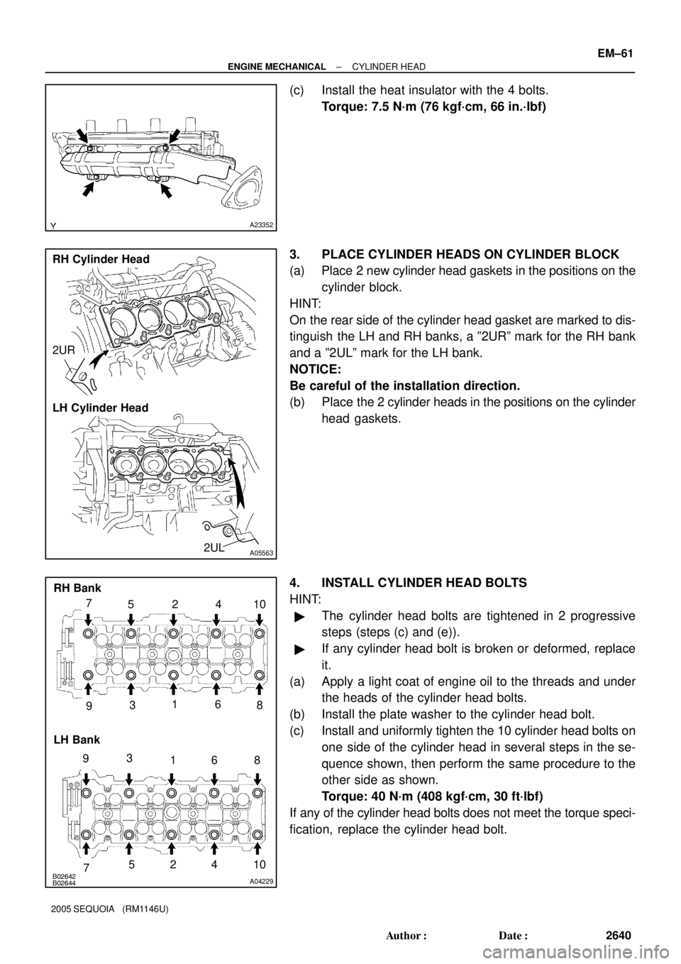
(c) Install the heat insulator with the 4 bolts.
Torque: 7.5 N´m (76 kgf´cm, 66 in.´lbf)
3. PLACE CYLINDER HEADS ON CYLINDER BLOCK
(a) Place 2 new cylinder head gaskets in the positions on the
cylinder block.
HINT:
On the rear side of the cylinder head gasket are marked to dis-
tinguish the LH and RH banks, a º2URº mark for the RH bank
and a º2ULº mark for the LH bank.
NOTICE:
Be careful of the installation direction.
(b) Place the 2 cylinder heads in the positions on the cylinder
head gaskets.
4. INSTALL CYLINDER HEAD BOLTS
HINT:
�The cylinder head bolts are tightened in 2 progressive
steps (steps (c) and (e)).
�If any cylinder head bolt is broken or deformed, replace
it.
(a) Apply a light coat of engine oil to the threads and under
the heads of the cylinder head bolts.
(b) Install the plate washer to the cylinder head bolt.
(c) Install and uniformly tighten the 10 cylinder head bolts on
one side of the cylinder head in several steps in the se-
quence shown, then perform the same procedure to the
other side as shown.
Torque: 40 N´m (408 kgf´cm, 30 ft´lbf)
If any of the cylinder head bolts does not meet the torque speci-
fication, replace the cylinder head bolt.
Page 2649 of 4323
B02643
B02645A04230
RH Bank
LH BankPortion A
Portion A
A04093
Painted Mark
90°
90°
Front
A02888
Camshaft Gear Spring
Wave WasherCamshaft Sub±gear
A02861
EM±62
± ENGINE MECHANICALCYLINDER HEAD
2641 Author�: Date�:
2005 SEQUOIA (RM1146U)
NOTICE:
Do not drop the plate washer for cylinder head bolt into por-
tion A of the cylinder head. If dropped into portion A, the
plate washer will pass through the cylinder head and cylin-
der block into the oil pan.
(d) Mark the front of the cylinder head bolt with paint.
(e) Retighten the cylinder head bolts by 90° in the numerical
order shown.
(f) Check that the painted mark is now at a 90° angle to front.
5. INSTALL SPARK PLUGS
6. ASSEMBLE EXHAUST CAMSHAFT
(a) Install the camshaft gear spring, camshaft sub±gear and
wave washer.
HINT:
Attach the pin on the gear to the gear spring end.
(b) Using snap ring pliers, install the snap ring.
Page 2650 of 4323
A02859
A02889
Service Bolt
SST
Sub Gear
Main Gear
Turn
A23353Front
A23343
5 mm Hexagon
Wrench SST
A03173
± ENGINE MECHANICALCYLINDER HEAD
EM±63
2642 Author�: Date�:
2005 SEQUOIA (RM1146U)
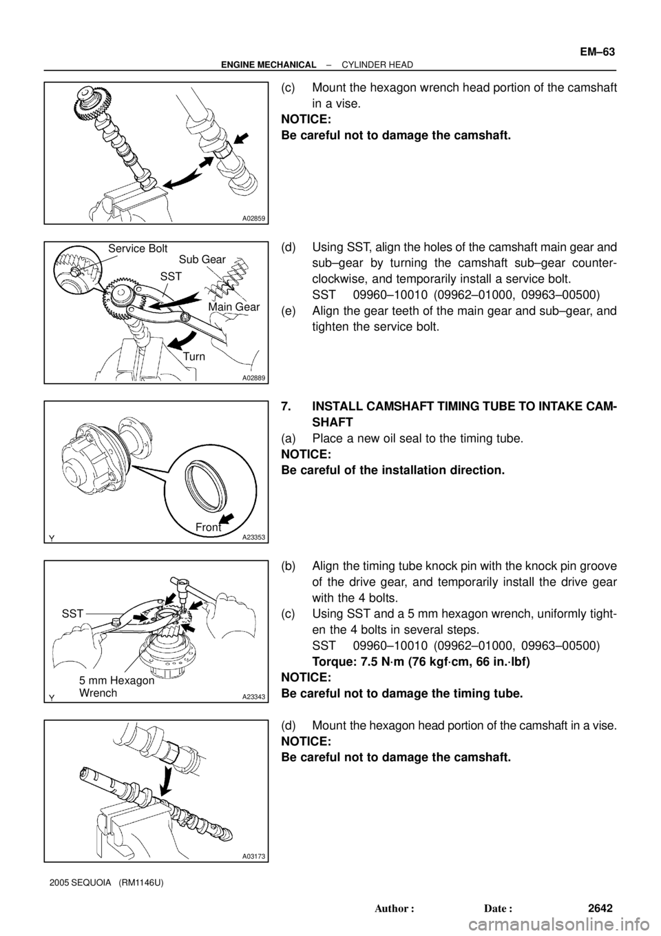
(c) Mount the hexagon wrench head portion of the camshaft
in a vise.
NOTICE:
Be careful not to damage the camshaft.
(d) Using SST, align the holes of the camshaft main gear and
sub±gear by turning the camshaft sub±gear counter-
clockwise, and temporarily install a service bolt.
SST 09960±10010 (09962±01000, 09963±00500)
(e) Align the gear teeth of the main gear and sub±gear, and
tighten the service bolt.
7. INSTALL CAMSHAFT TIMING TUBE TO INTAKE CAM-
SHAFT
(a) Place a new oil seal to the timing tube.
NOTICE:
Be careful of the installation direction.
(b) Align the timing tube knock pin with the knock pin groove
of the drive gear, and temporarily install the drive gear
with the 4 bolts.
(c) Using SST and a 5 mm hexagon wrench, uniformly tight-
en the 4 bolts in several steps.
SST 09960±10010 (09962±01000, 09963±00500)
Torque: 7.5 N´m (76 kgf´cm, 66 in.´lbf)
NOTICE:
Be careful not to damage the timing tube.
(d) Mount the hexagon head portion of the camshaft in a vise.
NOTICE:
Be careful not to damage the camshaft.
Page 2652 of 4323
A23355
A16831
Seal Packing
Seal Width
1.5 mm
A23356
± ENGINE MECHANICALCYLINDER HEAD
EM±65
2644 Author�: Date�:
2005 SEQUOIA (RM1146U)
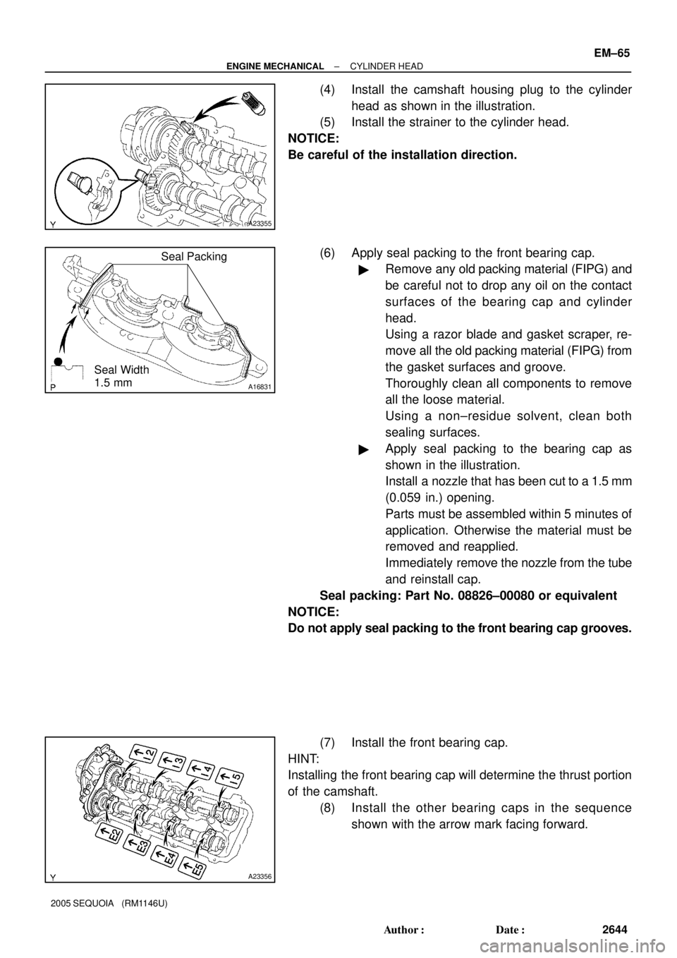
(4) Install the camshaft housing plug to the cylinder
head as shown in the illustration.
(5) Install the strainer to the cylinder head.
NOTICE:
Be careful of the installation direction.
(6) Apply seal packing to the front bearing cap.
�Remove any old packing material (FIPG) and
be careful not to drop any oil on the contact
surfaces of the bearing cap and cylinder
head.
Using a razor blade and gasket scraper, re-
move all the old packing material (FIPG) from
the gasket surfaces and groove.
Thoroughly clean all components to remove
all the loose material.
Using a non±residue solvent, clean both
sealing surfaces.
�Apply seal packing to the bearing cap as
shown in the illustration.
Install a nozzle that has been cut to a 1.5 mm
(0.059 in.) opening.
Parts must be assembled within 5 minutes of
application. Otherwise the material must be
removed and reapplied.
Immediately remove the nozzle from the tube
and reinstall cap.
Seal packing: Part No. 08826±00080 or equivalent
NOTICE:
Do not apply seal packing to the front bearing cap grooves.
(7) Install the front bearing cap.
HINT:
Installing the front bearing cap will determine the thrust portion
of the camshaft.
(8) Install the other bearing caps in the sequence
shown with the arrow mark facing forward.
Page 2653 of 4323
A23357
Push
A23337
A
B
C
D
E A
BC
D E
E
EE
EEE
EEEE
EE
A23337
1
4
22
8
9 2
321
6 10
17
18
5
71314
19121115
1620
A23335
Service Bolt EM±66
± ENGINE MECHANICALCYLINDER HEAD
2645 Author�: Date�:
2005 SEQUOIA (RM1146U)
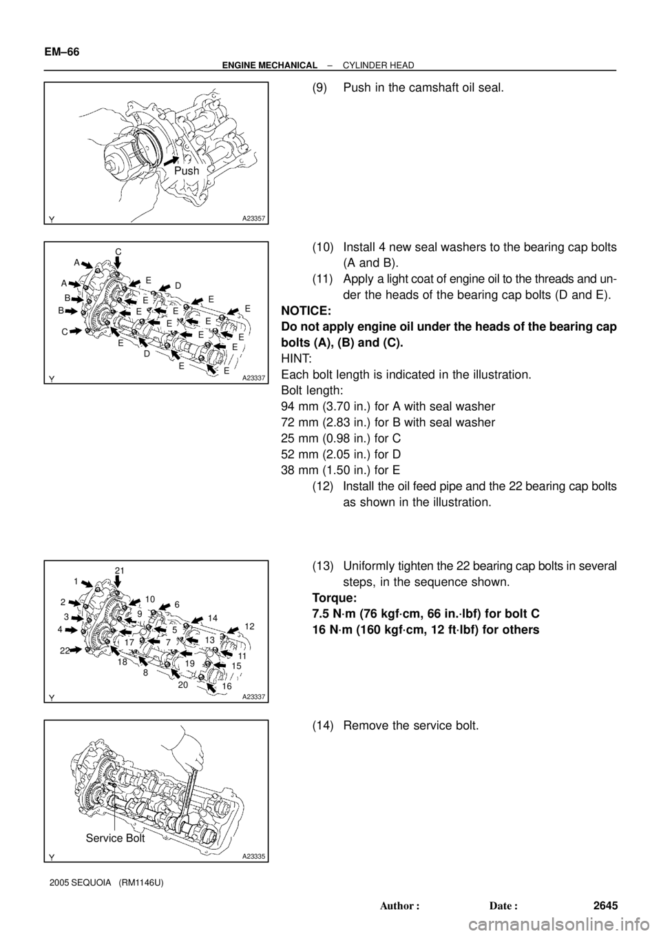
(9) Push in the camshaft oil seal.
(10) Install 4 new seal washers to the bearing cap bolts
(A and B).
(11) Apply a light coat of engine oil to the threads and un-
der the heads of the bearing cap bolts (D and E).
NOTICE:
Do not apply engine oil under the heads of the bearing cap
bolts (A), (B) and (C).
HINT:
Each bolt length is indicated in the illustration.
Bolt length:
94 mm (3.70 in.) for A with seal washer
72 mm (2.83 in.) for B with seal washer
25 mm (0.98 in.) for C
52 mm (2.05 in.) for D
38 mm (1.50 in.) for E
(12) Install the oil feed pipe and the 22 bearing cap bolts
as shown in the illustration.
(13) Uniformly tighten the 22 bearing cap bolts in several
steps, in the sequence shown.
Torque:
7.5 N´m (76 kgf´cm, 66 in.´lbf) for bolt C
16 N´m (160 kgf´cm, 12 ft´lbf) for others
(14) Remove the service bolt.