Page 2623 of 4323
EM1X0±01
A02844
EM±36
± ENGINE MECHANICALCYLINDER HEAD
2615 Author�: Date�:
2005 SEQUOIA (RM1146U)
REMOVAL
1. DRAIN ENGINE COOLANT
2. REMOVE THROTTLE BODY COVER
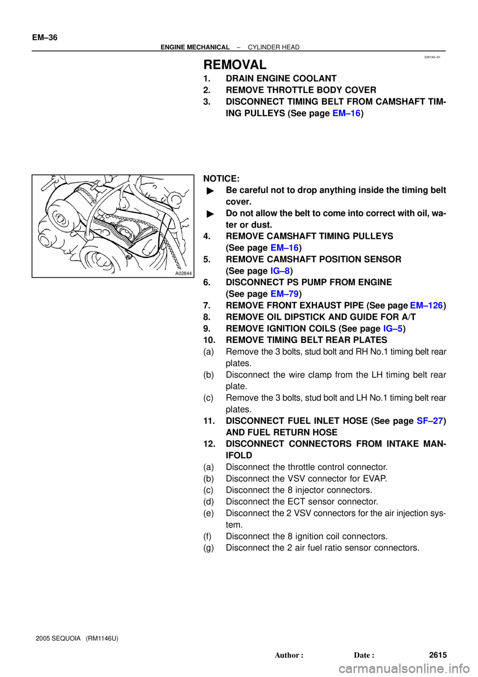
3. DISCONNECT TIMING BELT FROM CAMSHAFT TIM-
ING PULLEYS (See page EM±16)
NOTICE:
�Be careful not to drop anything inside the timing belt
cover.
�Do not allow the belt to come into correct with oil, wa-
ter or dust.
4. REMOVE CAMSHAFT TIMING PULLEYS
(See page EM±16)
5. REMOVE CAMSHAFT POSITION SENSOR
(See page IG±8)
6. DISCONNECT PS PUMP FROM ENGINE
(See page EM±79)
7. REMOVE FRONT EXHAUST PIPE (See page EM±126)
8. REMOVE OIL DIPSTICK AND GUIDE FOR A/T
9. REMOVE IGNITION COILS (See page IG±5)
10. REMOVE TIMING BELT REAR PLATES
(a) Remove the 3 bolts, stud bolt and RH No.1 timing belt rear
plates.
(b) Disconnect the wire clamp from the LH timing belt rear
plate.
(c) Remove the 3 bolts, stud bolt and LH No.1 timing belt rear
plates.
11. DISCONNECT FUEL INLET HOSE (See page SF±27)
AND FUEL RETURN HOSE
12. DISCONNECT CONNECTORS FROM INTAKE MAN-
IFOLD
(a) Disconnect the throttle control connector.
(b) Disconnect the VSV connector for EVAP.
(c) Disconnect the 8 injector connectors.
(d) Disconnect the ECT sensor connector.
(e) Disconnect the 2 VSV connectors for the air injection sys-
tem.
(f) Disconnect the 8 ignition coil connectors.
(g) Disconnect the 2 air fuel ratio sensor connectors.
Page 2627 of 4323
A04456
No.2 Idler
Pulley Bolt
Timing
Mark
Crankshaft
Pulley Bolt
A23334
Movement
(25°)
SSTOil Control Valve
Installation Hole
A23335Service Bolt
A23336
EM±40
± ENGINE MECHANICALCYLINDER HEAD
2619 Author�: Date�:
2005 SEQUOIA (RM1146U)
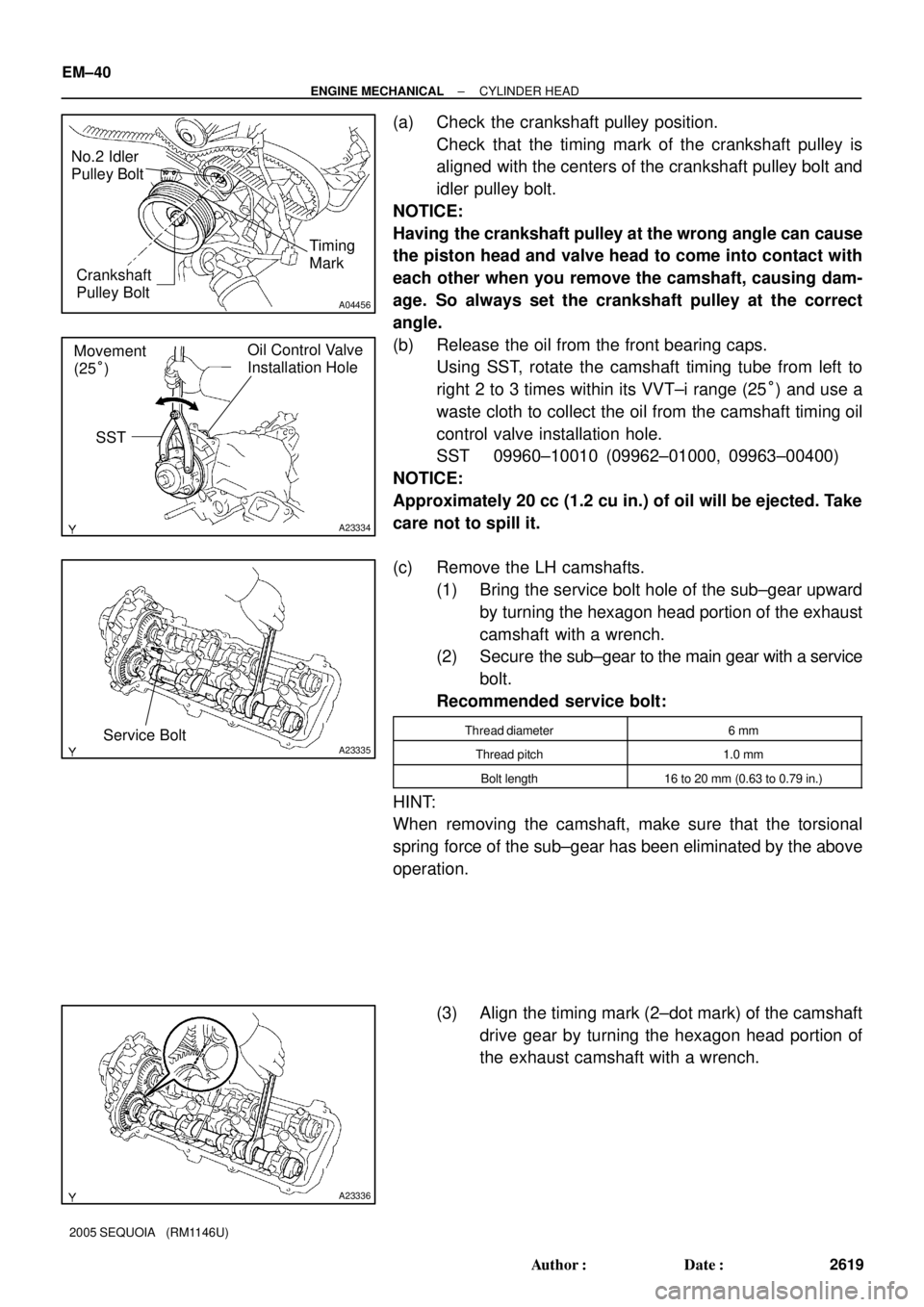
(a) Check the crankshaft pulley position.
Check that the timing mark of the crankshaft pulley is
aligned with the centers of the crankshaft pulley bolt and
idler pulley bolt.
NOTICE:
Having the crankshaft pulley at the wrong angle can cause
the piston head and valve head to come into contact with
each other when you remove the camshaft, causing dam-
age. So always set the crankshaft pulley at the correct
angle.
(b) Release the oil from the front bearing caps.
Using SST, rotate the camshaft timing tube from left to
right 2 to 3 times within its VVT±i range (25°) and use a
waste cloth to collect the oil from the camshaft timing oil
control valve installation hole.
SST 09960±10010 (09962±01000, 09963±00400)
NOTICE:
Approximately 20 cc (1.2 cu in.) of oil will be ejected. Take
care not to spill it.
(c) Remove the LH camshafts.
(1) Bring the service bolt hole of the sub±gear upward
by turning the hexagon head portion of the exhaust
camshaft with a wrench.
(2) Secure the sub±gear to the main gear with a service
bolt.
Recommended service bolt:
Thread diameter6 mm
Thread pitch1.0 mm
Bolt length16 to 20 mm (0.63 to 0.79 in.)
HINT:
When removing the camshaft, make sure that the torsional
spring force of the sub±gear has been eliminated by the above
operation.
(3) Align the timing mark (2±dot mark) of the camshaft
drive gear by turning the hexagon head portion of
the exhaust camshaft with a wrench.
Page 2628 of 4323
A23337
12
345
6
7
811
12 13
14
15
1617
18 2122
910 1920
A23338
Service Bolt
A23339
Approx.
10°
A23340
1 2
21
22
19 20
7
8 11
12
13
14
15
16
3
4 17
18
5
6 9
10
± ENGINE MECHANICALCYLINDER HEAD
EM±41
2620 Author�: Date�:
2005 SEQUOIA (RM1146U)
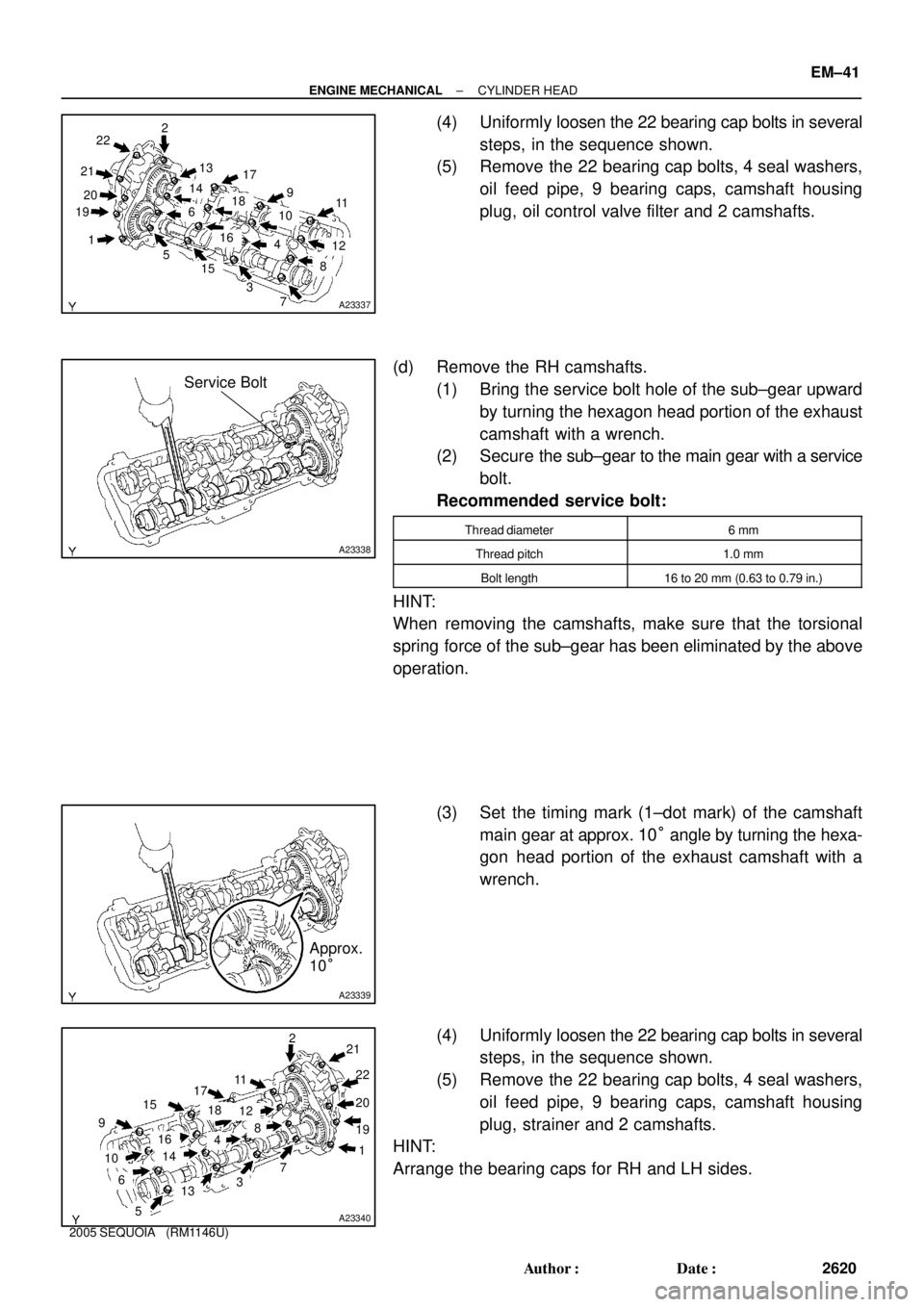
(4) Uniformly loosen the 22 bearing cap bolts in several
steps, in the sequence shown.
(5) Remove the 22 bearing cap bolts, 4 seal washers,
oil feed pipe, 9 bearing caps, camshaft housing
plug, oil control valve filter and 2 camshafts.
(d) Remove the RH camshafts.
(1) Bring the service bolt hole of the sub±gear upward
by turning the hexagon head portion of the exhaust
camshaft with a wrench.
(2) Secure the sub±gear to the main gear with a service
bolt.
Recommended service bolt:
Thread diameter6 mm
Thread pitch1.0 mm
Bolt length16 to 20 mm (0.63 to 0.79 in.)
HINT:
When removing the camshafts, make sure that the torsional
spring force of the sub±gear has been eliminated by the above
operation.
(3) Set the timing mark (1±dot mark) of the camshaft
main gear at approx. 10° angle by turning the hexa-
gon head portion of the exhaust camshaft with a
wrench.
(4) Uniformly loosen the 22 bearing cap bolts in several
steps, in the sequence shown.
(5) Remove the 22 bearing cap bolts, 4 seal washers,
oil feed pipe, 9 bearing caps, camshaft housing
plug, strainer and 2 camshafts.
HINT:
Arrange the bearing caps for RH and LH sides.
Page 2630 of 4323
A233435 mm Hexagon Wrench SST
B02642B02644A04229
RH Bank
LH Bank1
23 4
5 6
7
89
10
3
1 5
7 10
9 8
6 2
4
B02643
B02645A04230
Portion A
Portion A RH Bank
LH Bank
± ENGINE MECHANICALCYLINDER HEAD
EM±43
2622 Author�: Date�:
2005 SEQUOIA (RM1146U)
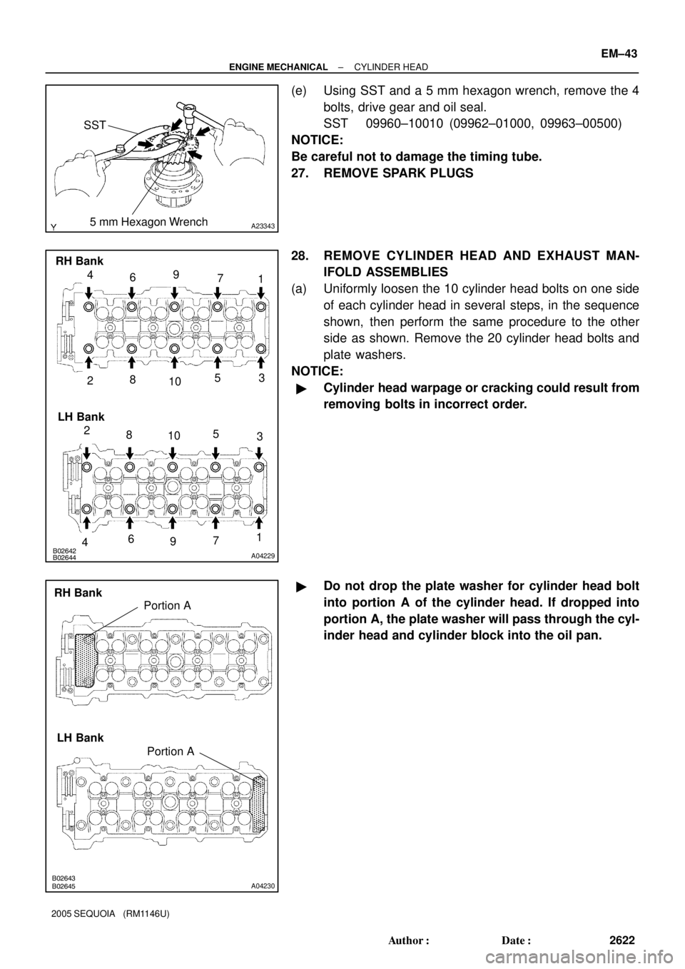
(e) Using SST and a 5 mm hexagon wrench, remove the 4
bolts, drive gear and oil seal.
SST 09960±10010 (09962±01000, 09963±00500)
NOTICE:
Be careful not to damage the timing tube.
27. REMOVE SPARK PLUGS
28. REMOVE CYLINDER HEAD AND EXHAUST MAN-
IFOLD ASSEMBLIES
(a) Uniformly loosen the 10 cylinder head bolts on one side
of each cylinder head in several steps, in the sequence
shown, then perform the same procedure to the other
side as shown. Remove the 20 cylinder head bolts and
plate washers.
NOTICE:
�Cylinder head warpage or cracking could result from
removing bolts in incorrect order.
�Do not drop the plate washer for cylinder head bolt
into portion A of the cylinder head. If dropped into
portion A, the plate washer will pass through the cyl-
inder head and cylinder block into the oil pan.
Page 2632 of 4323
EM0L1±09
A03191SST
A03192
± ENGINE MECHANICALCYLINDER HEAD
EM±45
2624 Author�: Date�:
2005 SEQUOIA (RM1146U)
DISASSEMBLY
1. REMOVE VALVE LIFTERS AND SHIMS
HINT:
Arrange the valve lifters and shims in correct order.
2. REMOVE VALVES
(a) Using SST, compress the valve spring and remove the 2
keepers.
SST 09202±70020 (09202±00010)
(b) Remove the spring retainer, the valve spring, the valve
and the spring seat.
HINT:
Arrange the valves, valve springs, spring seats and spring re-
tainers incorrect order.
(c) Using needle±nose pliers, remove the oil seal.
Page 2633 of 4323
EM1X1±01
A03194
A03193
EM6323
EM6324
P21861
EM±46
± ENGINE MECHANICALCYLINDER HEAD
2625 Author�: Date�:
2005 SEQUOIA (RM1146U)
INSPECTION
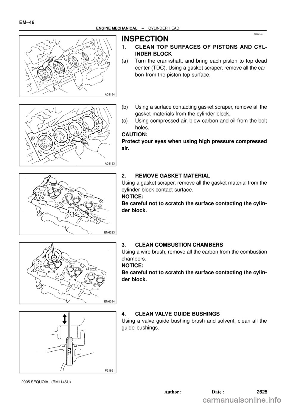
1. CLEAN TOP SURFACES OF PISTONS AND CYL-
INDER BLOCK
(a) Turn the crankshaft, and bring each piston to top dead
center (TDC). Using a gasket scraper, remove all the car-
bon from the piston top surface.
(b) Using a surface contacting gasket scraper, remove all the
gasket materials from the cylinder block.
(c) Using compressed air, blow carbon and oil from the bolt
holes.
CAUTION:
Protect your eyes when using high pressure compressed
air.
2. REMOVE GASKET MATERIAL
Using a gasket scraper, remove all the gasket material from the
cylinder block contact surface.
NOTICE:
Be careful not to scratch the surface contacting the cylin-
der block.
3. CLEAN COMBUSTION CHAMBERS
Using a wire brush, remove all the carbon from the combustion
chambers.
NOTICE:
Be careful not to scratch the surface contacting the cylin-
der block.
4. CLEAN VALVE GUIDE BUSHINGS
Using a valve guide bushing brush and solvent, clean all the
guide bushings.
Page 2635 of 4323
EM0580
A04087A04091A04236
Z00052
Z00054
44.5° EM±48
± ENGINE MECHANICALCYLINDER HEAD
2627 Author�: Date�:
2005 SEQUOIA (RM1146U)
9. CLEAN VALVES
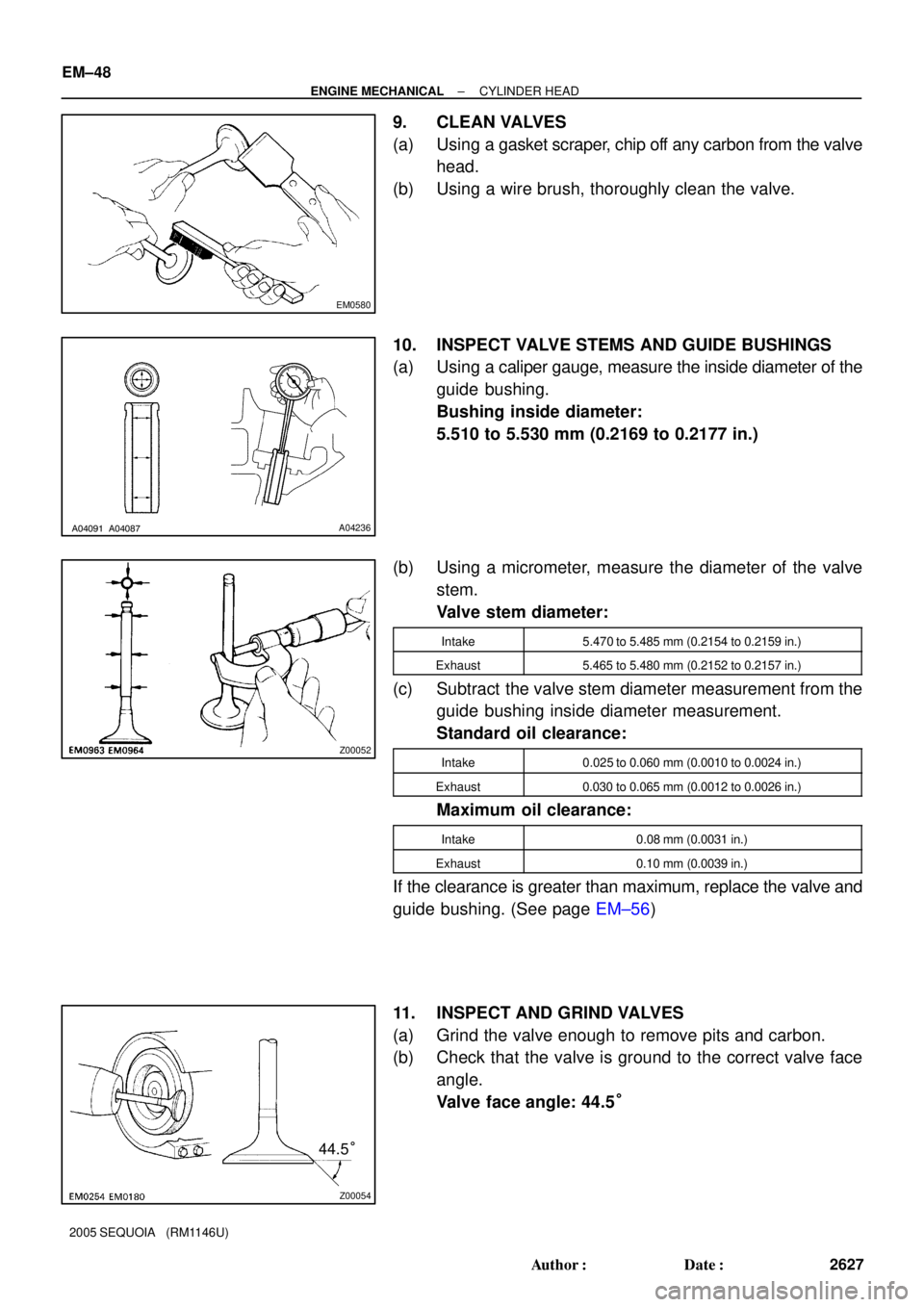
(a) Using a gasket scraper, chip off any carbon from the valve
head.
(b) Using a wire brush, thoroughly clean the valve.
10. INSPECT VALVE STEMS AND GUIDE BUSHINGS
(a) Using a caliper gauge, measure the inside diameter of the
guide bushing.
Bushing inside diameter:
5.510 to 5.530 mm (0.2169 to 0.2177 in.)
(b) Using a micrometer, measure the diameter of the valve
stem.
Valve stem diameter:
Intake5.470 to 5.485 mm (0.2154 to 0.2159 in.)
Exhaust5.465 to 5.480 mm (0.2152 to 0.2157 in.)
(c) Subtract the valve stem diameter measurement from the
guide bushing inside diameter measurement.
Standard oil clearance:
Intake0.025 to 0.060 mm (0.0010 to 0.0024 in.)
Exhaust0.030 to 0.065 mm (0.0012 to 0.0026 in.)
Maximum oil clearance:
Intake0.08 mm (0.0031 in.)
Exhaust0.10 mm (0.0039 in.)
If the clearance is greater than maximum, replace the valve and
guide bushing. (See page EM±56)
11. INSPECT AND GRIND VALVES
(a) Grind the valve enough to remove pits and carbon.
(b) Check that the valve is ground to the correct valve face
angle.
Valve face angle: 44.5°
Page 2639 of 4323
A04022
A23346
A23347
Turn
EM3322
A04083
Plastigage
EM±52
± ENGINE MECHANICALCYLINDER HEAD
2631 Author�: Date�:
2005 SEQUOIA (RM1146U)
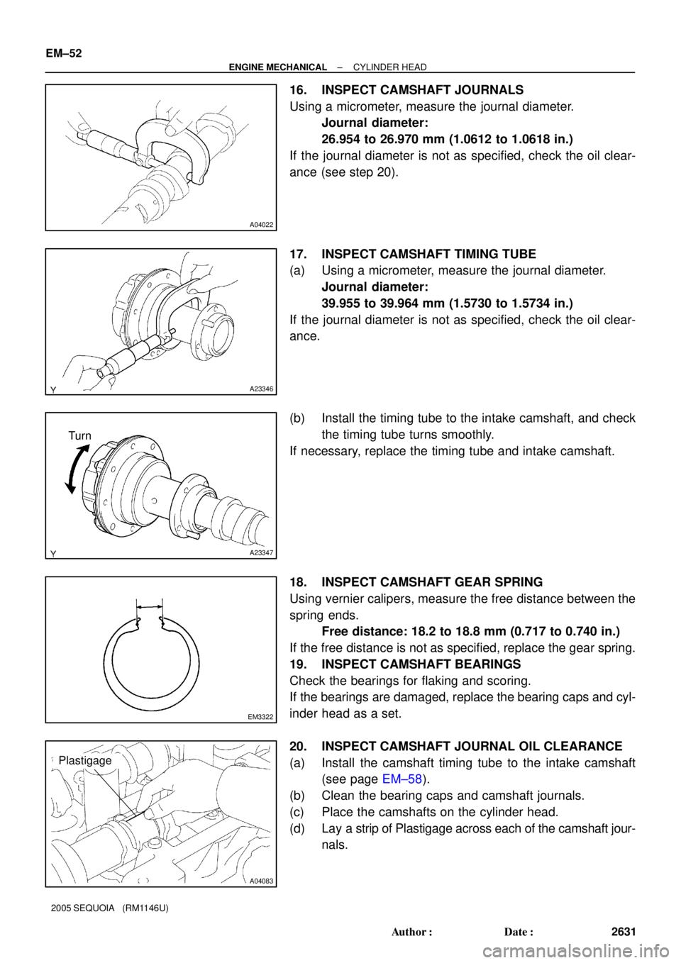
16. INSPECT CAMSHAFT JOURNALS
Using a micrometer, measure the journal diameter.
Journal diameter:
26.954 to 26.970 mm (1.0612 to 1.0618 in.)
If the journal diameter is not as specified, check the oil clear-
ance (see step 20).
17. INSPECT CAMSHAFT TIMING TUBE
(a) Using a micrometer, measure the journal diameter.
Journal diameter:
39.955 to 39.964 mm (1.5730 to 1.5734 in.)
If the journal diameter is not as specified, check the oil clear-
ance.
(b) Install the timing tube to the intake camshaft, and check
the timing tube turns smoothly.
If necessary, replace the timing tube and intake camshaft.
18. INSPECT CAMSHAFT GEAR SPRING
Using vernier calipers, measure the free distance between the
spring ends.
Free distance: 18.2 to 18.8 mm (0.717 to 0.740 in.)
If the free distance is not as specified, replace the gear spring.
19. INSPECT CAMSHAFT BEARINGS
Check the bearings for flaking and scoring.
If the bearings are damaged, replace the bearing caps and cyl-
inder head as a set.
20. INSPECT CAMSHAFT JOURNAL OIL CLEARANCE
(a) Install the camshaft timing tube to the intake camshaft
(see page EM±58).
(b) Clean the bearing caps and camshaft journals.
(c) Place the camshafts on the cylinder head.
(d) Lay a strip of Plastigage across each of the camshaft jour-
nals.