Page 3749 of 4323
I21419
Water Valve
Air Outlet
Servomotor
Heater Radiator
Thermistor
Evaporator
Expansion Valve Power Transistor Blower Motor
AC±14
± AIR CONDITIONINGAIR CONDITIONING SYSTEM
3741 Author�: Date�:
2005 SEQUOIA (RM1146U)
Page 3759 of 4323

COOLING UNIT
ON±VEHICLE INSPECTION
1. INSPECT FOR LEAKAGE OF REFRIGERANT
(a) Remove the co")
AC3GV±02
I21372
I21373
AC±24
± AIR CONDITIONINGCOOLING UNIT
3751 Author�: Date�:
2005 SEQUOIA (RM1146U)
COOLING UNIT
ON±VEHICLE INSPECTION
1. INSPECT FOR LEAKAGE OF REFRIGERANT
(a) Remove the console box assembly.
(b) Remove the glove compartment door.
(c) Remove the lower No. 2 finish panel.
(d) Remove the heater to register duct No. 4.
(e) Remove the lower LH finish panel.
(f) Remove the lower cover (See page BO±89).
(g) Remove the blower controller.
(1) Disconnect the connector.
(2) Remove the 2 screws and blower motor linear con-
troller.
(h) Using a gas leak detector, check for leakage.
If there is leakage, check the tightening torque at the joints or
check the evaporator.
(i) Install the blower motor linear controller with the 2 screws.
(j) Install the lower cover.
(k) Install the lower LH finish panel.
(l) Install the lower No.2 finish panel.
(m) Install the glove compartment door (See page BO±97).
2. INSPECT EXPANSION VALVE
(a) Set the manifold gauge set.
(b) Run the engine.
(c) Check quantity of gas with the sight glass in refrigeration
cycle.
(1) Run the engine at 1,500 rpm for at least 5 minutes.
(2) Then check that the high pressure reading is 1.37
to 1.57 Mpa (14 to 16 kgm/cm
2, 199 to 228 psi).
(d) Check the expansion valve.
If the expansion valve is faulty, the low pressure reading will
drop to 0 kPa (0 kgf/cm
2, 0 psi).
HINT:
When the low pressure reading drops to 0 kPa (0 kgf/cm
2, 0
psi), there is no difference in temperature between the IN and
OUT sides of the receiver.
3. INSPECT THERMISTOR RESISTANCE
(a) Disconnect the connector.
(b) Measure the resistance between terminals.
Standard resistance: 1,500 W at 25°C (77°F)
If resistance is not as specified, replace the thermistor.
Page 3760 of 4323
AC3GW±02
I21420
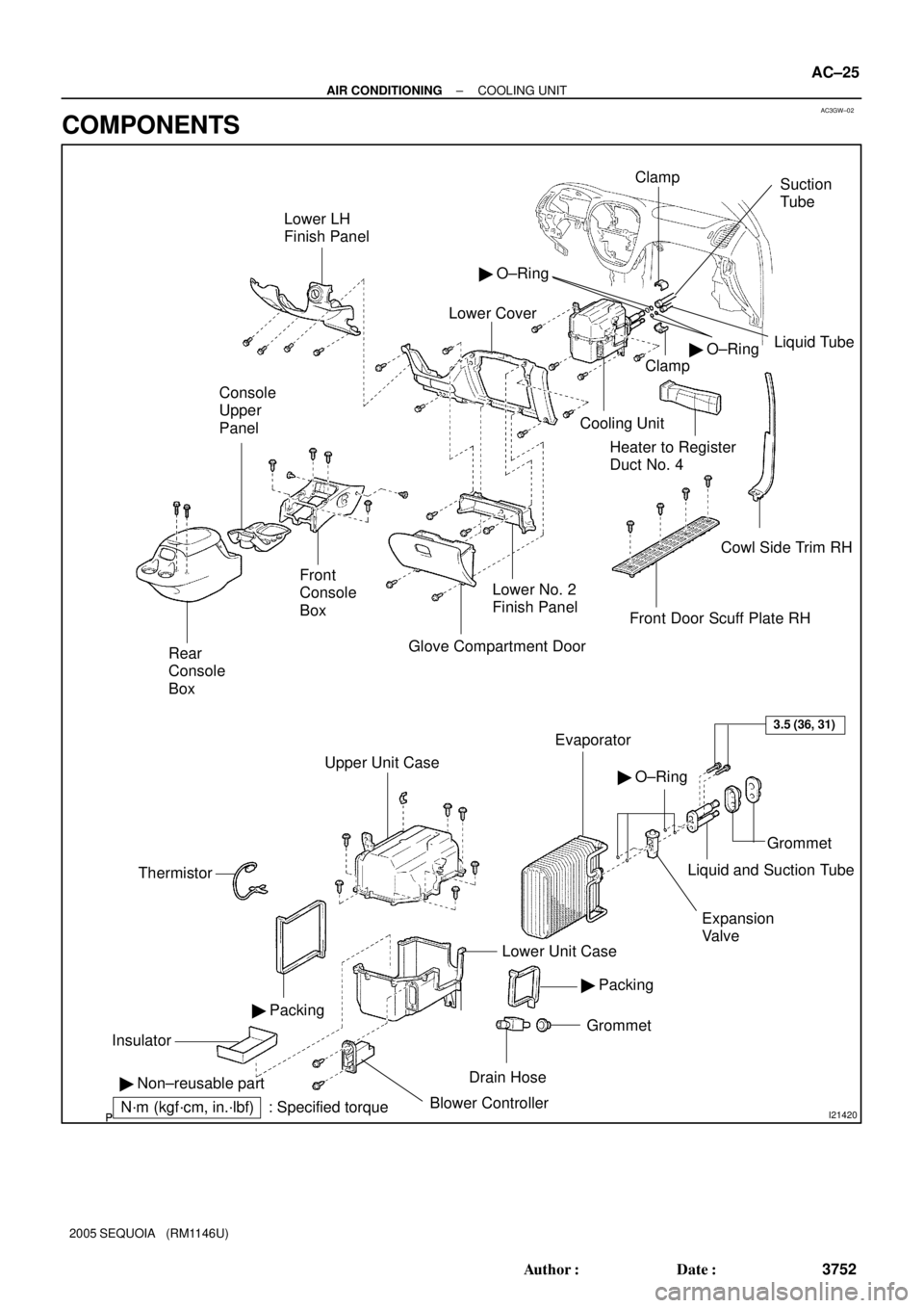
Lower LH
Finish Panel
Lower Cover
� O±Ring
Suction
Tube
Liquid Tube
� O±Ring
Clamp
Cooling Unit
Heater to Register
Duct No. 4
Cowl Side Trim RH
Front Door Scuff Plate RH
Lower No. 2
Finish Panel
Glove Compartment Door
Upper Unit Case
Evaporator
Thermistor
Lower Unit Case
� Packing� O±Ring
Grommet
Drain Hose� Packing
Blower Controller
N´m (kgf´cm, in.´lbf) : Specified torque � Non±reusable part
3.5 (36, 31)
Liquid and Suction Tube
Expansion
Valve
Clamp
GrommetInsulator
Front
Console
Box Console
Upper
Panel
Rear
Console
Box
± AIR CONDITIONINGCOOLING UNIT
AC±25
3752 Author�: Date�:
2005 SEQUOIA (RM1146U)
COMPONENTS
Page 3762 of 4323
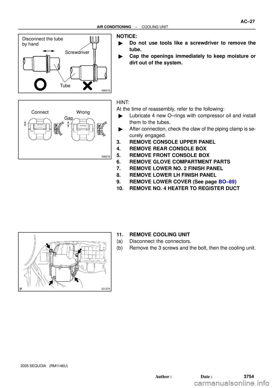
I06919
Disconnect the tube
by hand
Screwdriver
Tube
I06878
Connect Wrong
Gap
I21374
± AIR CONDITIONINGCOOLING UNIT
AC±27
3754 Author�: Date�:
2005 SEQUOIA (RM1146U)
NOTICE:
�Do not use tools like a screwdriver to remove the
tube.
�Cap the openings immediately to keep moisture or
dirt out of the system.
HINT:
At the time of reassembly, refer to the following:
�Lubricate 4 new O±rings with compressor oil and install
them to the tubes.
�After connection, check the claw of the piping clamp is se-
curely engaged.
3. REMOVE CONSOLE UPPER PANEL
4. REMOVE REAR CONSOLE BOX
5. REMOVE FRONT CONSOLE BOX
6. REMOVE GLOVE COMPARTMENT PARTS
7. REMOVE LOWER NO. 2 FINISH PANEL
8. REMOVE LOWER LH FINISH PANEL
9. REMOVE LOWER COVER (See page BO±89)
10. REMOVE NO. 4 HEATER TO REGISTER DUCT
11. REMOVE COOLING UNIT
(a) Disconnect the connectors.
(b) Remove the 3 screws and the bolt, then the cooling unit.
Page 3767 of 4323
AC3H2±02
I21423
Non±reusable part �Instrument Panel
Reinforcement Defroster Nozzle
Center Heater To Register Duct
Brace No.1
Brace No.2
Heater To
Register Duct
No. 1
Heater Unit
Cooling Unit
Heater Radiator
Foot Air Duct Air Vent DuctHeater Unit Case � O±Ring
ClampGrommet
Heater Radiator
PipePacking
Clamp
Clamp
Clamp
Air Outlet Servomotor
Aspirator Hose
Air Mix Servomotor
Heater to
Register
Duct No. 4
Rear Foot Duct
AC±32
± AIR CONDITIONINGHEATER UNIT
3759 Author�: Date�:
2005 SEQUOIA (RM1146U)
HEATER UNIT
COMPONENTS
Page 3768 of 4323

AC3H3±02
I11129
I11197
Water Hose
Heater Radiator
PipeUpper
LH
RH
45 ± 10°
Lower
Hose Clip
Second RidgeLH
RH
I11130
± AIR CONDITIONINGHEATER UNIT
AC±33
3760 Author�: Date�:
2005 SEQUOIA (RM1146U)
REMOVAL
1. REMOVE COOLING UNIT (See page AC±26)
2. DRAIN ENGINE COOLANT FROM RADIATOR
HINT:
It is not necessary to drain out all the coolant.
3. DISCONNECT WATER VALVE CONTROL CABLE
FROM WATER VALVE (See page AC±79)
4. DISCONNECT WATER HOSES FROM HEATER RA-
DIATOR PIPES
(a) Using pliers, grip the claws of the clips and slide the clips
along the hose.
(b) Disconnect the water hoses.
(c) Remove the grommet.
HINT:
At the time of installation, refer to the following:
�Push the water hose onto the heater radiator pipe up to
the second ridge on the pipe.
�Install the hose clip to the position shown in the illustra-
tion.
5. REMOVE INSTRUMENT PANEL AND REINFORCE-
MENT (See page BO±89)
6. REMOVE DEFROSTER NOZZLE AND HEATER TO
REGISTER DUCT
7. REMOVE HEATER UNIT
Remove the 3 screws and heater unit.
Page 3769 of 4323
I21798
AC3H4±02
AC±34
± AIR CONDITIONINGHEATER UNIT
3761 Author�: Date�:
2005 SEQUOIA (RM1146U)
DISASSEMBLY
1. REMOVE HEATER RADIATOR
(a) Remove the 3 screws and 3 clamps.
(b) Pull out the heater radiator.
(c) Remove the 2 screws and 2 clips, then disconnect the
heater radiator pipes.
2. REMOVE AIR VENT DUCT
Remove the 3 screws and duct.
3. REMOVE AIR OUTLET SERVOMOTOR
Remove the 3 screws and servomotor.
4. REMOVE AIR MIX SERVOMOTOR
Remove the 3 screws and servomotor.
5. REMOVE ASPIRATOR HOSE
Page 3770 of 4323
AC3H5±02
I22635
FACE
B/L
FOOT
F/D
DEF
2
1 8
7
6
5
4
± AIR CONDITIONINGHEATER UNIT
AC±35
3762 Author�: Date�:
2005 SEQUOIA (RM1146U)
INSPECTION
1. INSPECT FINS FOR BLOCKAGE
If the fins are clogged, clean them with compressed air.
2. INSPECT AIR OUTLET SERVOMOTOR OPERATION
(a) Connect the positive (+) lead from the battery to terminal
2 and the negative (±) lead to terminal 1.
(b) Connect the negative (±) lead from the battery to each ter-
minal and check that the shaft rotates at each position, as
shown in the illustration.
Connected terminalPosition
4DEF
5F/D
6FOOT
7B/L
8FACE