Page 3429 of 4323

I28399
Fusible Link Block:
Relays: Fuses:
5. RR HEATER Fuse 30 A
A. C/OPN Relay
B. HEAD Relay
C. EFI Relay
D. FUEL PUMP Relay
E. DEFOG Relay
F. HORN Relay
Engine Room J/B6. R/B Fuse 30 A
7. A/PUMP Fuse 50 A
8. ABS Fuse 60 A
9. ALT Fuse 140 A
10. CDS FAN Fuse 25 A
11. Spare Fuse 15 A
12. Spare Fuse 20 A
13. Spare Fuse 30 A
14. Main Fuse 40 A
15. DOOR No. 2 Fuse 30 A
16. *2 H±LP RH Fuse 15 A
17. EFI No. 1 Fuse 20 A
18. ETCS Fuse 10 A19. *1.DRL Fuse 15 A
*2.H±LP LH Fuse 15 A
20. ALT±S Fuse 7.5 A
21. TOWING Fuse 30 A
22. ST Fuse 30 A
23. RAD No. 3 Fuse 30 A
24. TURN±HAZ Fuse 20 A
25. AM2 Fuse 25 A
26. EFI No. 2 Fuse 10 A
27. SHORT±PIN
28. HORN Fuse 10 A
29. MIR HTR Fuse 15 A
30. ECU±B Fuse 7.5 A
31. DOME Fuse 10 A
32. RAD No. 1 Fuse 20 A
*1 w/ Daytime Running Light
*2 w/o Daytime Running Light 15
16 17 18
19 20 21
262728
2930
A
B
C
D
EF 1
234
5
6789
10
22 2324 25
31
32
11
12
13141. TOWING R/B Fuse 50 A
2. AIR SUS Fuse 50 A
3. HEATER Fuse 50 A
4. DEFOG Fuse 40 A
± BODY ELECTRICALPOWER SOURCE
BE±17
3421 Author�: Date�:
2005 SEQUOIA (RM1146U)
Page 3430 of 4323
I28550
Engine Room R/B No. 3:
Relays: Fuses:
1. TOWING BRK Fuse 30 A
A. BATT CHARGE Relay
B. TOWING TAIL Relay 2. BATT CHARGE Fuse 30 A
3. TOWING TAIL Fuse 30 A
Driver Side R/B:
Relays:
A. INVERTER Relay
B. SEAT HEATER RelayEngine Room R/B No. 4:
Relays:
A. RR HEATER Relay
B. HEATER Relay BE±18
± BODY ELECTRICALPOWER SOURCE
3422 Author�: Date�:
2005 SEQUOIA (RM1146U)
Page 3476 of 4323
BE0TC±09
I28412
Mirror Assembly
� Mirror Heater
Rear Window Defogger
Instrument Panel J/B
� MIRROR HEATER Relay
Ignition Switch Rear Defogger SwitchEngine Room J/B
� DEFOG Relay
� MIR HTR Fuse
BE±64
± BODY ELECTRICALDEFOGGER SYSTEM
3468 Author�: Date�:
2005 SEQUOIA (RM1146U)
DEFOGGER SYSTEM
LOCATION
Page 3478 of 4323

I05027
2
13 5
2 5
135
I01291
Tester Probe
Tin FoilHeat Wire
I01292
At Center
I01293
0 Volts
Broken
WireSeveral
Volts
Battery
Side Ground SideFoil Strip
� � BE±66
± BODY ELECTRICALDEFOGGER SYSTEM
3470 Author�: Date�:
2005 SEQUOIA (RM1146U)
4. INSPECT MIRROR HEATER RELAY CONTINUITY
ConditionTester connectionSpecified condition
Always1 ± 2Continuity
Always3 ± 5No continuity
Apply B+ between
terminals 1 and 2.3 ± 5Continuity
If continuity is not as specified, replace the relay.
5. INSPECT DEFOGGER WIRE
NOTICE:
�When cleaning the glass, use a soft, dry cloth, and
wipe the glass in the direction of the wire. Take care
not to damage the wires.
�Do not use detergents or glass cleaners with abrasive
ingredients.
�When measuring voltage, wrap a piece of tin foil
around the tip of the negative probe and press the foil
against the wire with your finger, as shown in the il-
lustration.
(a) Turn the ignition switch ON.
(b) Turn the defogger switch ON.
(c) Inspect the voltage at the center of each heat wire, as
shown.
VoltageCriteria
Approx. 5 VOkay (No break in wire)
Approx. 10 V or 0 VBroken wire
HINT:
If there is approximately 10 V, the wire is broken between the
center of the wire and the positive (+) end. If there is no voltage,
the wire is broken between the center of the wire and ground.
(d) Place the voltmeter positive (+) lead against the defogger
wire on the battery side.
(e) Place the voltmeter negative (±) lead with the foil strip
against the wire on the ground side.
(f) Slide the positive (+) lead from the battery to the ground
side.
(g) The point where the voltmeter deflects from several V to
zero V is the place where the defogger wire is broken.
HINT:
If the heat wire is not broken, the voltmeter indicates 0 V at the
positive (+) end of the heat wire but gradually increases to about
12 V as the meter probe moves to the other end.
Page 3479 of 4323

6. IF NECESSARY, REPAIR DEFO")
I01294
Repair Point
Broken
Wire
Masking Tape
I01295
I18583
6 4
I24872
78
I28509
5
12
± BODY ELECTRICALDEFOGGER SYSTEM
BE±67
3471 Author�: Date�:
2005 SEQUOIA (RM1146U)
6. IF NECESSARY, REPAIR DEFOGGER WIRE
(a) Clean the broken wire tips with grease, wax and silicon re-
mover.
(b) Place the masking tape along both sides of the wire for
repair.
(c) Thoroughly mix the repair agent (Dupont paste No.
4817).
(d) Using a fine tip brush, apply a small amount of the agent
to the wire.
(e) After a few minutes, remove the masking tape.
(f) Do not repair the defogger wire for at least 24 hours.
7. w/o Retract Mirror and Driving Position Memory:
INSPECT MIRROR HEATER OPERATION
(a) Connect the positive (+) lead from the battery to terminal
6 and the negative (±) lead to terminal 4.
(b) Check that the mirror becomes warm.
HINT:
It will take a short time for the mirror to become warm.
If operation is not as specified, replace the mirror.
8. w/ Retract Mirror only:
INSPECT MIRROR HEATER OPERATION
(a) Connect the positive (+) lead from the battery to terminal
7 and the negative (±) lead to terminal 8.
(b) Check that the mirror becomes warm.
HINT:
It will take a short time for the mirror to become warm.
If operation is not as specified, replace the mirror.
9. w/ Retract Mirror and Driving Position Memory:
INSPECT MIRROR HEATER OPERATION
(a) Connect the positive (+) lead from the battery to terminal
5 and the negative (±) lead to terminal 12.
(b) Check that the mirror becomes warm.
HINT:
It will take a short time for the mirror to become warm.
If operation is not as specified, replace the mirror.
Page 3510 of 4323
BE0GM±16
I28417
Transmitter
Door Lock Assembly Ignition Switch
Door Lock Assembly
Wireless Door Lock
Control Receiver
(Located behind the heater control panel)
BE±98
± BODY ELECTRICALWIRELESS DOOR LOCK CONTROL SYSTEM
3502 Author�: Date�:
2005 SEQUOIA (RM1146U)
LOCATION
Page 3535 of 4323
BE0GH±22
I28421
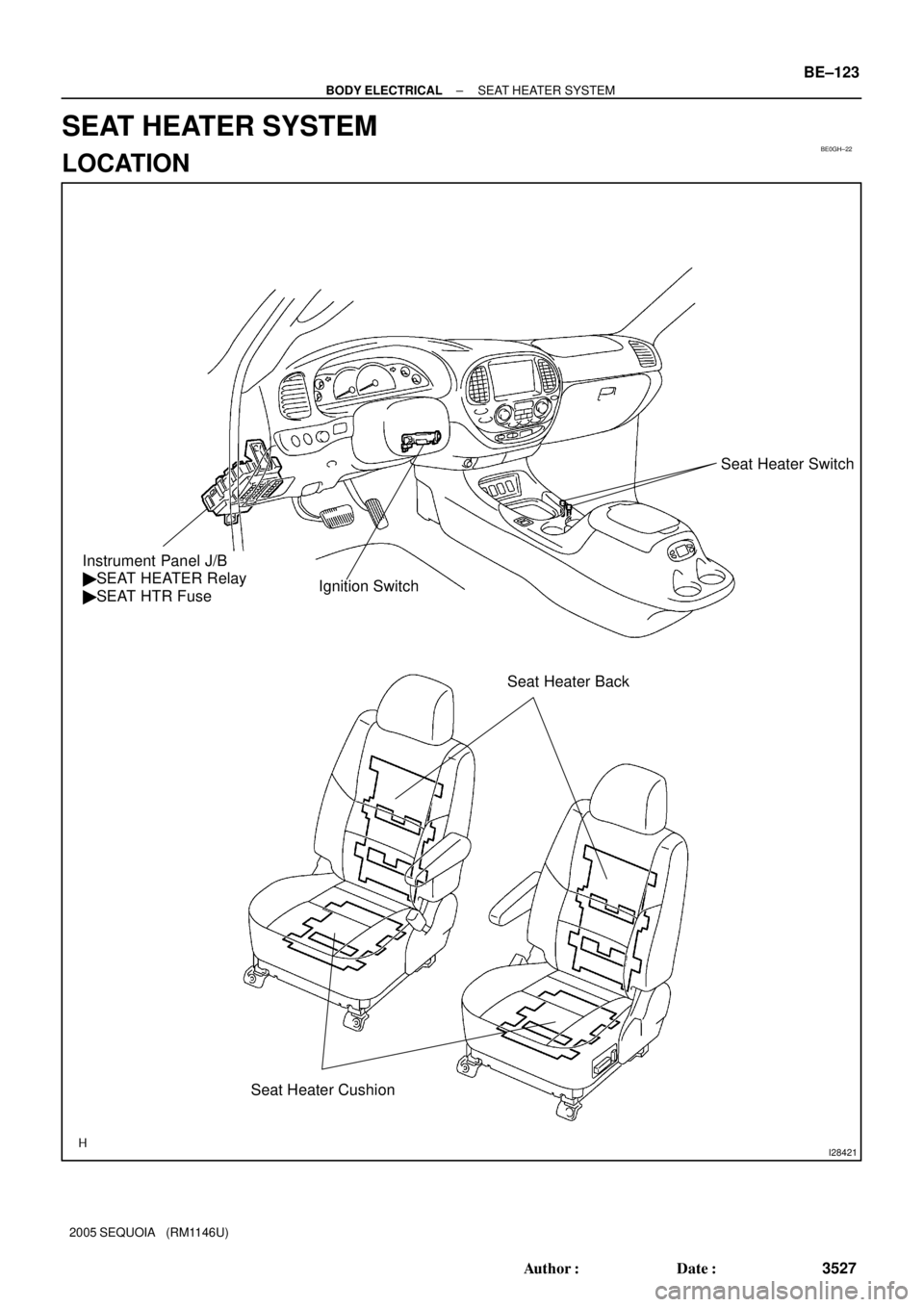
Ignition SwitchSeat Heater Switch
Instrument Panel J/B
� SEAT HEATER Relay
� SEAT HTR Fuse
Seat Heater CushionSeat Heater Back
± BODY ELECTRICALSEAT HEATER SYSTEM
BE±123
3527 Author�: Date�:
2005 SEQUOIA (RM1146U)
SEAT HEATER SYSTEM
LOCATION
Page 3536 of 4323
BE2D7±03
I18566
Left Side Heater Switch
Right Side Heater Switch
I18567
6
4
6
4
BE±124
± BODY ELECTRICALSEAT HEATER SYSTEM
3528 Author�: Date�:
2005 SEQUOIA (RM1146U)
INSPECTION
1. INSPECT SEAT HEATER SWITCH CONTINUITY
Switch positionTester connectionSpecified condition
Right side3 ± 4 ± 6Continuity
OFF±No continuity
Left side3 ± 4 ± 6Continuity
Illumination circuit1 ± 2Continuity
If continuity is not as specified, replace the switch.
2. INSPECT SEAT HEATER INDICATOR LIGHT OPERA-
TION
(a) Connect the positive (+) lead from the battery to terminal
4 and the negative (±) lead to terminal 6.
(b) Push the seat heater switch (right or left side) and check
that the indicator light comes on.
If operation is not as specified, replace the switch.


BE±98
± BODY ELECTRICALWIRELESS DOOR")