Page 3196 of 4323
BR10G±04
F16311
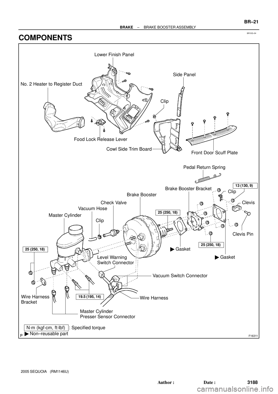
Master CylinderVacuum Hose
Level Warning
Switch ConnectorBrake Booster
� GasketClevis Pin Brake Booster Bracket Clip
: Specified torque
N´m (kgf´cm, ft´lbf)
� Non±reusable partPedal Return Spring
Wire Harness
Bracket
Lower Finish Panel
Food Lock Release Lever No. 2 Heater to Register Duct
Cowl Side Trim Board
Front Door Scuff Plate
� GasketClevis
Vacuum Switch Connector
19.5 (195, 14)
25 (250, 18)
25 (250, 18)
ClipCheck Valve
25 (250, 18)
Side Panel
Wire Harness
13 (130, 9)
Clip
Master Cylinder
Presser Sensor Connector
± BRAKEBRAKE BOOSTER ASSEMBLY
BR±21
3188 Author�: Date�:
2005 SEQUOIA (RM1146U)
COMPONENTS
Page 3197 of 4323
BR10H±05
BR3753
BR±22
± BRAKEBRAKE BOOSTER ASSEMBLY
3189 Author�: Date�:
2005 SEQUOIA (RM1146U)
REMOVAL
1. REMOVE MASTER CYLINDER (See page BR±16)
2. DISCONNECT VACUUM HOSE FROM BRAKE
BOOSTER
3. DISCONNECT 2 VACUUM SWITCH CONNECTORS
FROM BRAKE BOOSTER
4. REMOVE FRONT DOOR SCUFF PLATE, COWL SIDE
TRIM BOARD, SIDE PANEL, LOWER FINISH PANEL
AND NO. 2 HEATER TO REGISTER DUCT (See page
BO±89)
5. REMOVE PEDAL RETURN SPRING
6. REMOVE CLIP AND CLEVIS PIN
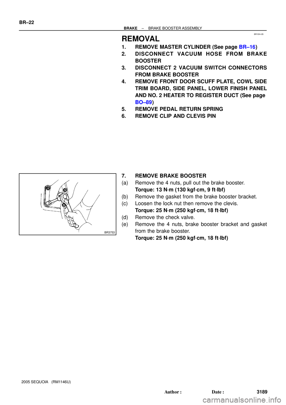
7. REMOVE BRAKE BOOSTER
(a) Remove the 4 nuts, pull out the brake booster.
Torque: 13 N´m (130 kgf´cm, 9 ft´lbf)
(b) Remove the gasket from the brake booster bracket.
(c) Loosen the lock nut then remove the clevis.
Torque: 25 N´m (250 kgf´cm, 18 ft´lbf)
(d) Remove the check valve.
(e) Remove the 4 nuts, brake booster bracket and gasket
from the brake booster.
Torque: 25 N´m (250 kgf´cm, 18 ft´lbf)
Page 3247 of 4323
SR1F3±03
F17895
Steering Wheel Pad
Steering
Wheel
Column Lower
CoverCombination
SwitchSteering Column Assembly
Transmission Control
Cable Assembly
Lower LH Finish PanelColumn Hole
Cover No. 2
No. 2 Universal
Joint Assembly
No. 2 Heater to Register Dust Torx® Screw
35 (360, 26)
35 (360, 26)
8.0 (82, 71 in.´lbf)
26 (260, 19)
26 (260, 19)
8.8 (90, 78 in.´lbf)
50 (510, 37)
8.8 (90, 78 in.´lbf)
Front Door Scuff PlateCowl Side Trim
Hood Lock
Release Lever
8.0 (82, 71 in.´lbf)
Side Panel
No. 2 Intermediate
Shaft AssemblyBrake Pedal
Return Spring
Column Upper Cover
N´m (kgf´cm, ft´lbf): Specified torque
Steering Wheel Lower
No. 3 Cover
Steering Wheel Lower
No. 2 Cover
35 (360, 26)
Sliding Yoke
Torx® Screw SR±12
± STEERINGTILT STEERING COLUMN
3239 Author�: Date�:
2005 SEQUOIA (RM1146U)
TILT STEERING COLUMN
COMPONENTS
Page 3250 of 4323

5. REMOVE COMBINATION SWITCH WITH SPIRAL
CABLE
(a) Disconnect the 4 connectors.")
F17896
A
BMatchmarks
F13260
F06703
± STEERINGTILT STEERING COLUMN
SR±15
3242 Author�: Date�:
2005 SEQUOIA (RM1146U)
5. REMOVE COMBINATION SWITCH WITH SPIRAL
CABLE
(a) Disconnect the 4 connectors.
(b) Disconnect the airbag connector.
(c) Remove the 3 screws and combination switch.
6. REMOVE SPIRAL CABLE (See page BE±26)
NOTICE:
Do not disassemble the cable or apply oil to it.
7. REMOVE COWL SIDE TRIM AND FRONT DOOR
SCUFF PLATE
8. REMOVE LOWER LH FINISH PANEL
(a) Remove the 2 screws and disconnect the hood lock re-
lease lever from the panel.
(b) Remove the 4 panel set bolts and lower LH finish panel.
9. REMOVE NO. 2 HEATER TO REGISTER DUCT
10. REMOVE BRAKE PEDAL RETURN SPRING
11. REMOVE SLIDING YOKE
(a) Put matchmarks on the sliding yoke and No. 2 intermedi-
ate shaft assembly.
(b) Remove the ºAº bolt.
(c) Remove the ºBº bolt.
(d) Slide the sliding yoke and remove it.
12. REMOVE COLUMN HOLE COVER NO. 2
Remove the 3 bolts and column hole cover No. 2.
13. DISCONNECT TRANSMISSION CONTROL CABLE
ASSEMBLY
Disconnect the cable assembly from the column shift lever as-
sembly.
14. REMOVE STEERING COLUMN ASSEMBLY WITH
NO. 2 UNIVERSAL JOINT ASSEMBLY
(a) Disconnect the connectors.
(b) Remove the 4 steering column set nuts.
(c) Pull out the steering column assembly with the No. 2 uni-
versal joint assembly connected.
Page 3259 of 4323

5. INSTALL COLUMN HOLE COVER NO. 2
Install the column hole cover No. 2 to t")
F13260
F17896
BMatchmarks
A
F19948
Mark
SR±24
± STEERINGTILT STEERING COLUMN
3251 Author�: Date�:
2005 SEQUOIA (RM1146U)
5. INSTALL COLUMN HOLE COVER NO. 2
Install the column hole cover No. 2 to the body with the 3 bolts.
Torque: 8.0 N´m (82 kgf´cm, 71 in.´lbf)
6. INSTALL SLIDING YOKE
(a) Align the matchmark on the sliding yoke with the one on
the No. 2 intermediate shaft assembly.
(b) Install the ºBº bolt.
Torque: 35 N´m (360 kgf´cm, 26 ft´lbf)
(c) Install the ºAº bolt.
Torque: 35 N´m (360 kgf´cm, 26 ft´lbf)
7. INSTALL BRAKE PEDAL RETURN SPRING
8. INSTALL NO. 2 HEATER TO REGISTER DUCT
9. INSTALL LOWER LH FINISH PANEL
(a) Install the lower LH finish panel with the 4 bolts.
(b) Connect the hood lock release lever with the 2 screws.
10. INSTALL COWL SIDE TRIM AND FRONT DOOR
SCUFF PLATE
11. INSTALL SPIRAL CABLE (See page BE±26)
12. INSTALL COMBINATION SWITCH WITH SPIRAL
CABLE
(a) Install the combination switch with the 3 screws.
(b) Connect the airbag connector.
(c) Connect the 4 connectors.
13. INSTALL UPPER AND LOWER COLUMN COVERS
Install the upper and lower column covers with the 3 screws.
14. CENTER SPIRAL CABLE
(a) Check that the front wheels are facing straight ahead.
(b) Turn the cable counterclockwise by hand until it feels firm.
(c) Then rotate the cable clockwise about 2.5 turns to align
the marks.
HINT:
The cable will rotate about 2.5 turns to both the left and right
from the center.
Page 3420 of 4323

DEFOGGER SYSTEM
SymptomSuspect AreaSee page
Rear window defogger does not operate.
1. HTR Fuse
2. DEFOG Fuse
3. DE")
BE±8
± BODY ELECTRICALTROUBLESHOOTING
3412 Author�: Date�:
2005 SEQUOIA (RM1146U)
DEFOGGER SYSTEM
SymptomSuspect AreaSee page
Rear window defogger does not operate.
1. HTR Fuse
2. DEFOG Fuse
3. DEFOG Relay
4. Defogger Switch (in A/C Panel Switch)
5. Defogger Wire
6. Wire HarnessBE±14
BE±14
BE±14
BE±65
BE±65
±
Mirror defogger does not operate.
1. MIR±HTR Fuse
2. HTR Fuse
3. Mirror Heater Relay
4. Mirror Heater
5. Wire HarnessBE±14
BE±14
BE±65
BE±65
±
POWER WINDOW CONTROL SYSTEM
This system uses the multiplex communication system, so check diagnosis system of the multiplex commu-
nication system before you proceed with troubleshooting.
SymptomSuspect AreaSee page
All the power windows do not operate.
(Power door lock system is normal.)
1. POWER MAIN Relay
2. Driver Door ECU (Power Window Master Switch)
3. Body ECU
4. Wire HarnessBE±69
DI±1788
±
±
Only the driver's window does not operate.
1. Power Window Motor
2. Power Window Pulse Sensor Circuit
3. Power Window Limit Switch Circuit
4. Driver Door ECU (Power Window Master Switch)BE±69
DI±1803
DI±1800
±
ºWindow lock functionº does not operate.Driver Door ECU (Power Window Master Switch)BE±69
Only the rear LH window does not operate.
1. Power Window Motor
2. Power Window Switch
3. Body ECUBE±69
BE±69
±
Only the rear RH window does not operate.
1. Power Window Motor
2. Power Window Switch
3. Body ECUBE±69
BE±69
±
Only the front passenger's window does not operate.
1. Power Window Motor
2. Power Window Pulse Sensor Circuit
3. Power Window Limit Switch Circuit
4. Passenger Door ECUBE±69
DI±1841
DI±1838
±
The Key related power window operations do not operate with
driver side door key cylinder.
(Master switch operation is normal.)1. Door Key Lock and Unlock Switch Circuit
2. Driver Door ECU (Power Window Master Switch)DI±1791
±
º Auto up º or º Auto down º does not operate. *1
1. Power Window Pulse Sensor Circuit
2. Power Window Limit Switch Circuit
3. Driver Door ECU (Power Window Master Switch)DI±1803
DI±1800
±
*1: º Auto up º or º Auto down º may not function when the manual switch is pressed and held for 2 sec. or
more with the window glass fully open or closed. In this case, by performing a sequence of the window glass
operations (full open, fully close and then half open), the function can be restored. If not, replace the driver
door ECU or passenger door ECU.
Page 3423 of 4323
 ºReclining Operationº does not operate.
1. Power Seat Switch (D, P)
2. Reclining Motor (D, P)
3. Wire HarnessBE")
± BODY ELECTRICALTROUBLESHOOTING
BE±11
3415 Author�: Date�:
2005 SEQUOIA (RM1146U) ºReclining Operationº does not operate.
1. Power Seat Switch (D, P)
2. Reclining Motor (D, P)
3. Wire HarnessBE±109
BE±109
±
ºLumbar Support Operationº does not operate.
1. Power Seat Switch (D)
2. Lumbar Support Motor (D)
3. Wire HarnessBE±109
BE±109
±
(D): Driver's Seat
(P): Passenger's Seat
POWER SEAT CONTROL SYSTEM (w/ Driving Position Memory)
This system uses the multiplex communication system, so check diagnosis system of the multiplex commu-
nication system before you proceed with troubleshooting.
SymptomSuspected AreaSee Page
Power seat control system abnormal operation.See DIAGNOSIS SYSTEMDI±1505
POWER MIRROR CONTROL SYSTEM (w/o Driving Position Memory)
This system uses the multiplex communication system, so check diagnosis system of the multiplex commu-
nication system before you proceed with troubleshooting.
SymptomSuspect AreaSee page
Mirror does not operate.1. Mirror Switch
2. Wire HarnessBE±115
±
Mirror operates abnormally.
1. Mirror Switch
2. Mirror Motor
3. Wire HarnessBE±115
BE±115
±
POWER MIRROR CONTROL SYSTEM (w/ Driving Position Memory)
SymptomSuspect AreaSee page
Remote control mirror LH only does not operate.
(w/ Driving position memory)1. Remote control mirror motor LH circuit
2. Remote control mirror position sensor LH circuit
3. Driver door ECUDI±1808
DI±1810
±
Remote control mirror RH only does not operate.
(w/ Driving position memory)1. Remote control mirror motor RH circuit
2. Remote control mirror position sensor RH circuit
3. Passenger door ECUDI±1845
DI±1847
±
ELECTRO CHROMIC MIRROR SYSTEM
SymptomSuspect AreaSee page
Electro Chromic Inner Mirror does not operate.
1. ECU±IG Fuse
2. Electro Chromic Inner Mirror
3. Wire HarnessBE±14
BE±122
±
SEAT HEATER SYSTEM
SymptomSuspect AreaSee page
Seat heaters do not operate.
(Driver's and Passenger's)
1. SEAT HTR Fuse
2. Seat Heater Switch (D, P)
3. Seat Heater
4. Wire HarnessBE±14
BE±124
BE±124
±
Driver's seat heater does not operate.1. Seat Heater Switch (D, P)
2. Wire HarnessBE±124
±
Passenger's seat heater does not operate.1. Seat Heater Switch (D, P)
2. Wire HarnessBE±124
±
Seat heater temperature is too hot.Seat HeaterBE±124
AUDIO SYSTEM
SymptomSuspect AreaSee page
Audio system abnormal operation.See DIAGNOSIS SYSTEMDI±1962
Page 3428 of 4323
I18638
A. Taillight Relay Instrument Panel J/B:
Relays:
B. Back±Up Light Relay
C. ACC Relay
D. Power Main Relay
E. Fog Light Relay
F. MIRROR HEATER Relay
G. FLASHER Relay
H. SEAT HEATER Relay
Fuses:
1. TAIL Fuse
2. PWR No. 4 Fuse
3. PANEL Fuse
4. ECU±IG Fuse
123
4567
89
1011
12
1314
A
BC
DE
GH
F
15
1617 18 19
20
21 22 23
2425
265. CIG Fuse
6. PWR No. 1 Fuse
7. HTR Fuse
8. WSH Fuse
9. RAD No. 2 Fuse
10. WIP Fuse
11. FOG Fuse
12. AC INV Fuse 15 A
13. 4WD Fuse14. IGN1 Fuse
15. GAUGE Fuse
16. IGN 2 Fuse
17. STOP Fuse
18. SUN ROOF Fuse
19. PWR OUTLET Fuse
20. PWR No. 3 Fuse
21. OBD Fuse
22. PWR No. 2 Fuse
23. SEAT HTR Fuse
24. PWR SEAT Fuse
25. AM1 Fuse
26. PWR No. 5 Fuse 15 A 10 A
20 A
7.5 A
10 A
15 A
25 A
10 A
25 A
7.5 A
25 A
15 A
20 A15 A
20 A
15 A
25 A
15 A
20 A
7.5 A
25 A
15 A
30 A
40 A
30 A BE±16
± BODY ELECTRICALPOWER SOURCE
3420 Author�: Date�:
2005 SEQUOIA (RM1146U)