Page 2508 of 4323
 Temperature Control: Output air is warmer or cooler than the set
temperature or response is slow
1. Refrige")
DI±2306
± DIAGNOSTICSAIR CONDITIONING SYSTEM
2500 Author�: Date�:
2005 SEQUOIA (RM1146U) Temperature Control: Output air is warmer or cooler than the set
temperature or response is slow
1. Refrigerant volume
2. Drive belt tension
3. Refrigeration system inspection with manifold gauge set
4. Cooling fan system
5. Solar sensor circuit
6. Rear room temp. sensor circuit
7. Ambient temp. sensor circuit
8. Rear evaporator temp. sensor circuit
9. Water valve damper position sensor circuit
10.Water valve damper control servomotor circuit
11. Condenser
12.Evaporator
13.Heater radiator
14.Expansion valve
15.Heater control assembly
16.Integration control and panelAC±23
AC±15
AC±3
AC±96
DI±2336
DI±2333
DI±2322
DI±2330
DI±2352
DI±2361
AC±65
AC±70
AC±45
AC±76
IN±35
IN±35
Temperature Control: No temperature control (only Max. cool or
Max. warm)
1. Rear room temp. sensor circuit
2. Ambient temp. sensor circuit
3. Water valve damper position sensor circuit
4. Water valve damper control servomotor circuit
5. Heater control assembly
6. Integration control and panelDI±2333
DI±2322
DI±2352
DI±2361
IN±35
IN±35
Page 2576 of 4323
Duty Ratio =A + BA
x 100 (%)
ON
OFFA
B
1 cycle
Blower Level
0
Si duty (%)
LO M1M2HI
29.2
42.4 55.5100
M3
70.9
I15873
Integration Control
and Panel
BLW From
Heater Relay
W±B
IGAGND
VM
SI J18
J/C+B
3
4L±B
1
G±B
I19
24 B3
Blower
Motor (Front)
12 L±WL±B
L±B
B4
Blower Motor
Linear Controller DI±2374
± DIAGNOSTICSAIR CONDITIONING SYSTEM
2568 Author�: Date�:
2005 SEQUOIA (RM1146U)
Blower Motor Circuit (Front A/C)
CIRCUIT DESCRIPTION
The blower motor is operated by signals from the integration
control and panel. Blower motor speed signals are transmitted
by changes in the Duty Ratio.
Duty Ratio
The duty ratio is the ratio of the period of continuity in one cycle.
For example, if A is the period of continuity in one cycle, and B
is the period of non±continuity, then.
WIRING DIAGRAM
DI7SL±08
Page 2579 of 4323
I28844
Integration Control
and Panel
2L16
7
R±WRrBLW
RrVM I21 21
BPBH122
G IJ3 A30
A/C Power Transistor
4LG W±G W±B
5 3
B15
Blower Motor
(Rear)12G W±GL
1 w/ Rear A/C:
From
RR Heater RelayI21 IJ3
W±B
A
J57
J/C
± DIAGNOSTICSAIR CONDITIONING SYSTEM
DI±2377
2571 Author�: Date�:
2005 SEQUOIA (RM1146U)
Blower Motor Circuit (Rear A/C)
CIRCUIT DESCRIPTION
This is power source for the blower motor.
WIRING DIAGRAM
DI8AF±06
Page 2619 of 4323
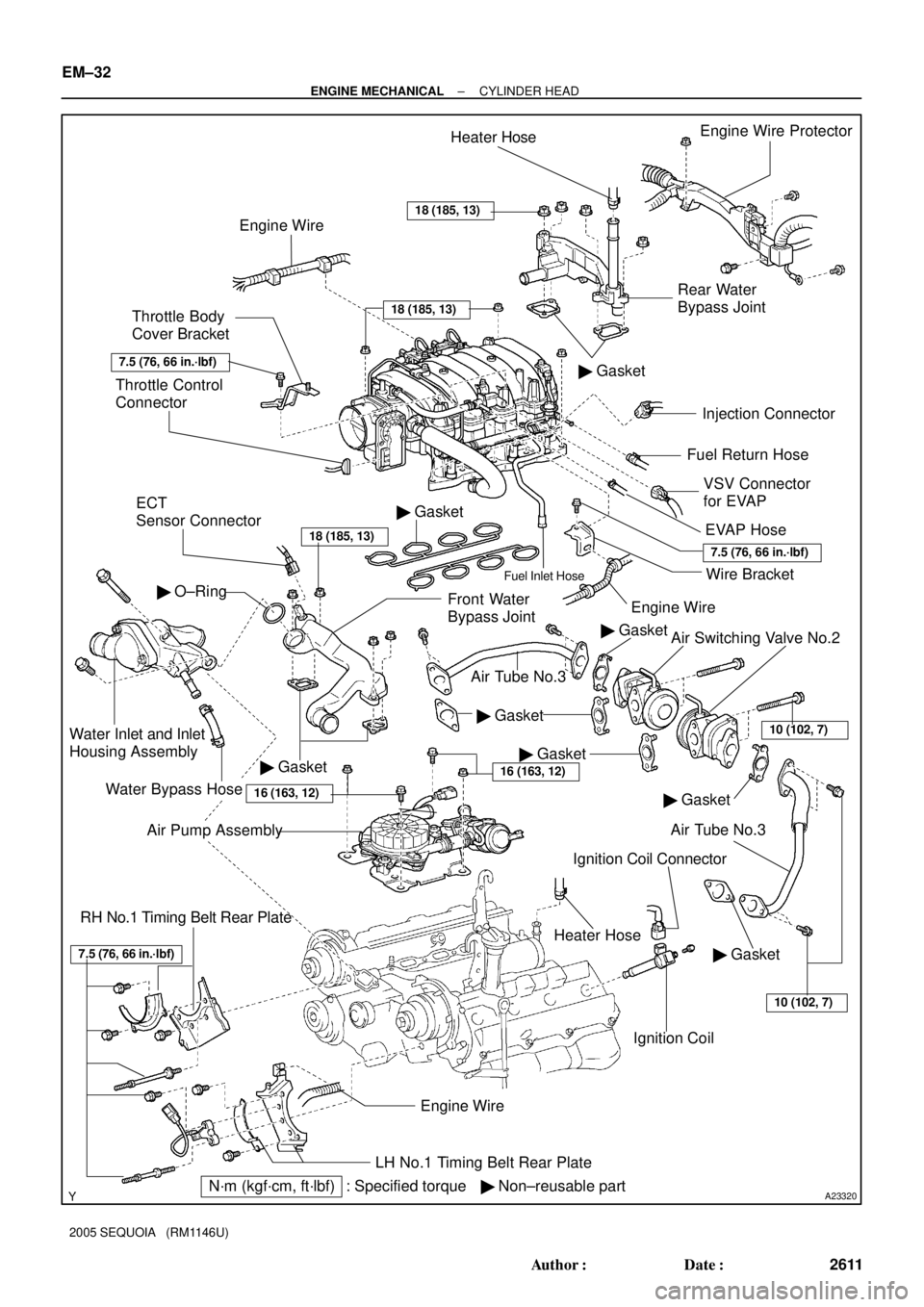
A23320
Rear Water
Bypass JointEngine Wire Protector
� Gasket
Injection Connector
Ignition Coil Connector
Ignition Coil Throttle Control
Connector
ECT
Sensor Connector
Front Water
Bypass Joint
Water Inlet and Inlet
Housing Assembly
Water Bypass Hose
LH No.1 Timing Belt Rear Plate
� Non±reusable partEngine Wire
� Gasket
� O±Ring
Engine WireHeater Hose
Throttle Body
Cover Bracket
VSV Connector
for EVAP Fuel Return Hose
Engine Wire
EVAP Hose
Heater Hose
Wire BracketFuel Inlet Hose
� Gasket
RH No.1 Timing Belt Rear Plate
� GasketAir Switching Valve No.2
Air Tube No.3
Air Tube No.3
� Gasket
N´m (kgf´cm, ft´lbf) : Specified torque� Gasket
18 (185, 13)
18 (185, 13)
18 (185, 13)
7.5 (76, 66 in.´lbf)
7.5 (76, 66 in.´lbf)
� Gasket
� Gasket
7.5 (76, 66 in.´lbf)
Air Pump Assembly
16 (163, 12)
10 (102, 7)
10 (102, 7)
16 (163, 12)
EM±32
± ENGINE MECHANICALCYLINDER HEAD
2611 Author�: Date�:
2005 SEQUOIA (RM1146U)
Page 2663 of 4323
A08928
ECM Connector ECM and Bracket AssemblyHeater to Register Dust
Lower No.2 Finish Panel
Glove Compartment Door
Wire Harness Connector (Cassette Connector)
A23366
Engine Wire Clamp
Engine WireHeater Hose Ground Strap
Fuel Inlet
HoseBattery
Negative
(±) Cable Heater Hose
Fuel Return
Hose
Generator Wire
Battery
Positive (+)
Terminal Clamp
Generator
Connector
EVAP Hose
w/o Hydraulic Brake Booster:
Brake Booster Tube
EM±76
± ENGINE MECHANICALENGINE UNIT (2WD)
2655 Author�: Date�:
2005 SEQUOIA (RM1146U)
Page 2667 of 4323

2659 Author�: Date�:
2005 SEQUOIA (RM1146U)
(d) Disconnect the hose clamp for the PS air hose.
(e) Disconnect the PS air hose from")
A09151
A08905
A08907
EM±80
± ENGINE MECHANICALENGINE UNIT (2WD)
2659 Author�: Date�:
2005 SEQUOIA (RM1146U)
(d) Disconnect the hose clamp for the PS air hose.
(e) Disconnect the PS air hose from the upper intake man-
ifold.
(f) Disconnect the 2 heater hoses.
(g) Disconnect the ground strap from the cowl panel.
(h) Disconnect the fuel inlet hose and clamps.
(i) Disconnect the fuel return hose and clamp.
(j) Disconnect the air inlet hose from the charcoal canister.
(k) Disconnect the EVAP hose from the charcoal canister.
(l) w/o Hydraulic brake booster:
Disconnect the brake booster tube.
11. REMOVE FRONT EXHAUST PIPES
(See page EM±126)
12. REMOVE PROPELLER SHAFT (See page PR±3)
13. REMOVE FRONT STABILIZER BAR
(See page SA±91)
14. DISCONNECT POWER STEERING GEAR PIPES
Disconnect the pressure feed tube, turn tube and pressure
tubes from the PS gear assembly.
(See page SR±40, SR±41)
15. REMOVE TRANSMISSION CONTROL CABLE
(a) Remove the 2 bolts and control cable bracket from the
transmission.
(b) Remove the control cable from the control shift lever.
16. DISCONNECT A/C COMPRESSOR FROM ENGINE
(a) Disconnect the A/C compressor connector.
(b) Remove the 3 bolts, and disconnect the A/C compressor
from the engine.
HINT:
Suspend the A/C compressor securely.
17. DISCONNECT PS PUMP FROM ENGINE
Remove the 3 bolts, and disconnect the PS pump from the en-
gine.
HINT:
Suspend the PS pump securely.
Page 2673 of 4323
 EM±86
± ENGINE MECHANICALENGINE UNIT (2WD)
2665 Author�: Date�:
2005 SEQUOIA (RM1146U)
11. INSTALL A/C COMPRESSOR
(a) Install the A/C compressor with the 3 bolts.
Torque: 49 N´m")
A08905
A09151
(a) EM±86
± ENGINE MECHANICALENGINE UNIT (2WD)
2665 Author�: Date�:
2005 SEQUOIA (RM1146U)
11. INSTALL A/C COMPRESSOR
(a) Install the A/C compressor with the 3 bolts.
Torque: 49 N´m (500 kgf´cm, 36 ft´lbf)
(b) Connect the A/C compressor connector.
12. INSTALL TRANSMISSION CONTROL CABLE
(a) Install the control cable to the control shift lever.
Torque: 13 N´m (130 kgf´cm, 9 ft´lbf)
(b) Install the control cable bracket to the transmission with
the 2 bolts.
13. CONNECT POWER STEERING GEAR PIPES
Connect the pressure feed tube, turn tube and turn pressure
tubes to the PS gear assembly. (See page SR±40, SR±41)
14. INSTALL FRONT STABILIZER BAR
(See page SA±93)
15. INSTALL PROPELLER SHAFT (See page PR±5)
16. INSTALL FRONT EXHAUST PIPES
(See page EM±126)
17. CONNECT HOSES, WIRES, CONNECTORS, CLAMPS,
GROMMET AND CABLES
(a) Connect the 2 PS air hoses to hose clamp on the No.3 RH
timing belt cover.
(b) Connect the generator wire.
(c) Connect the generator connector.
(d) Connect the hose clamp for the PS air hose.
(e) Connect the PS air hose to the upper intake manifold.
(f) Connect the 2 heater hoses.
(g) Connect the ground strap connector.
(h) Connect the fuel inlet hose and clamps.
(i) Connect the fuel return hose and clamp.
(j) Connect the air inlet hose to the charcoal canister.
(k) Connect the EVAP hose to the charcoal canister.
(l) Connect the brake booster tube.
18. CONNECT ENGINE WIRE TO CABIN
(a) Push into the engine wire through the cowl panel.
Page 2676 of 4323
A08928
ECM Connector ECM and Bracket AssemblyHeater to Register Dust
Lower No.2 Finish Panel
Glove Compartment Door
Wire Harness Connector (Cassette Connector)
A23366
Engine Wire Clamp
Engine WireHeater Hose Ground Strap
Fuel Inlet
HoseBattery
Negative
(±) Cable Heater Hose
Fuel Return
Hose
Generator Wire
Battery
Positive (+)
Terminal Clamp
Generator
Connector
EVAP Hose
w/o Hydraulic Brake Booster:
Brake Booster Tube
± ENGINE MECHANICALENGINE UNIT (4WD)
EM±89
2668 Author�: Date�:
2005 SEQUOIA (RM1146U)

ON
OFFA
B
1 cycle
Blower Level
0
Si duty (%)
LO M1M2HI
29.2
42.4 55.5100
M3
70.9
I15873
Integration Control
and Panel
BLW From
Heater Relay
W±B
IGAGND
VM
SI J18
J/C+B
3")
12G W±GL
1 w/ Rear A/C:
From
RR Heater RelayI21 IJ3")

A23366
Engine Wire Clamp
Engine WireHeat")

A23366
Engine Wire Clamp
Engine WireHeat")