Page 3537 of 4323

I18624
I18623
I18625
Wire Harness Side:
± BODY ELECTRICALSEAT HEATER SYSTEM
BE±125
3529 Author�: Date�:
2005 SEQUOIA (RM1146U)
3. INSPECT SEAT HEATER CUSHION CONTINUITY
(a) Heat the thermostat with a light.
(b) Inspect the seat heater cushion continuity between termi-
nals, as shown.
Tester connectionConditionSpecified condition
2 ± 4AlwaysContinuity
1 ± 3Seat heater temperature below 30°C (86°F)Continuity
1 ± 3Seat heater temperature above 40°C (104°F)No continuity
If continuity is not as specified, replace the seat cushion pad.
4. INSPECT SEAT BACK CONTINUITY
(a) Heat the thermostat with a light.
(b) Inspect the seat heater cushion continuity between termi-
nals, as shown.
Tester connectionConditionSpecified condition
2 ± 3AlwaysContinuity
1 ± 2, 1 ± 3Seat heater temperature below 30°C (86°F)Continuity
1 ± 2, 1 ± 3Seat heater temperature above 50°C (122°F)No continuity
If continuity is not as specified, replace the seat back pad.
5. INSPECT SEAT HEATER CUSHION CIRCUIT
Inspect the seat heater inner cushion and front cushion continu-
ity between terminals, as shown.
Page 3538 of 4323
I18626
Wire Harness Side:
I0502712
3 5
1
2 3
5
BE±126
± BODY ELECTRICALSEAT HEATER SYSTEM
3530 Author�: Date�:
2005 SEQUOIA (RM1146U)Tester connection
ConditionSpecified condition
1 ± Body groundSeat heater switch ONBattery positive voltage
If continuity is not as specified, replace the seat back pad.
6. INSPECT SEAT BACK CONTINUITY
Inspect the seat back continuity between terminals, as shown.
Tester connectionConditionSpecified condition
1 ± Body groundAlwaysContinuity
If continuity is not as specified, replace the seat back pad.
7. INSPECT SEAT HEATER RELAY CONTINUITY
ConditionTester connectionSpecified condition
Always1 ± 2Continuity
Always3 ± 5No continuity
Apply B+ between
terminals 1 and 2.3 ± 5Continuity
If continuity is not as specified, replace the relay.
Page 3646 of 4323

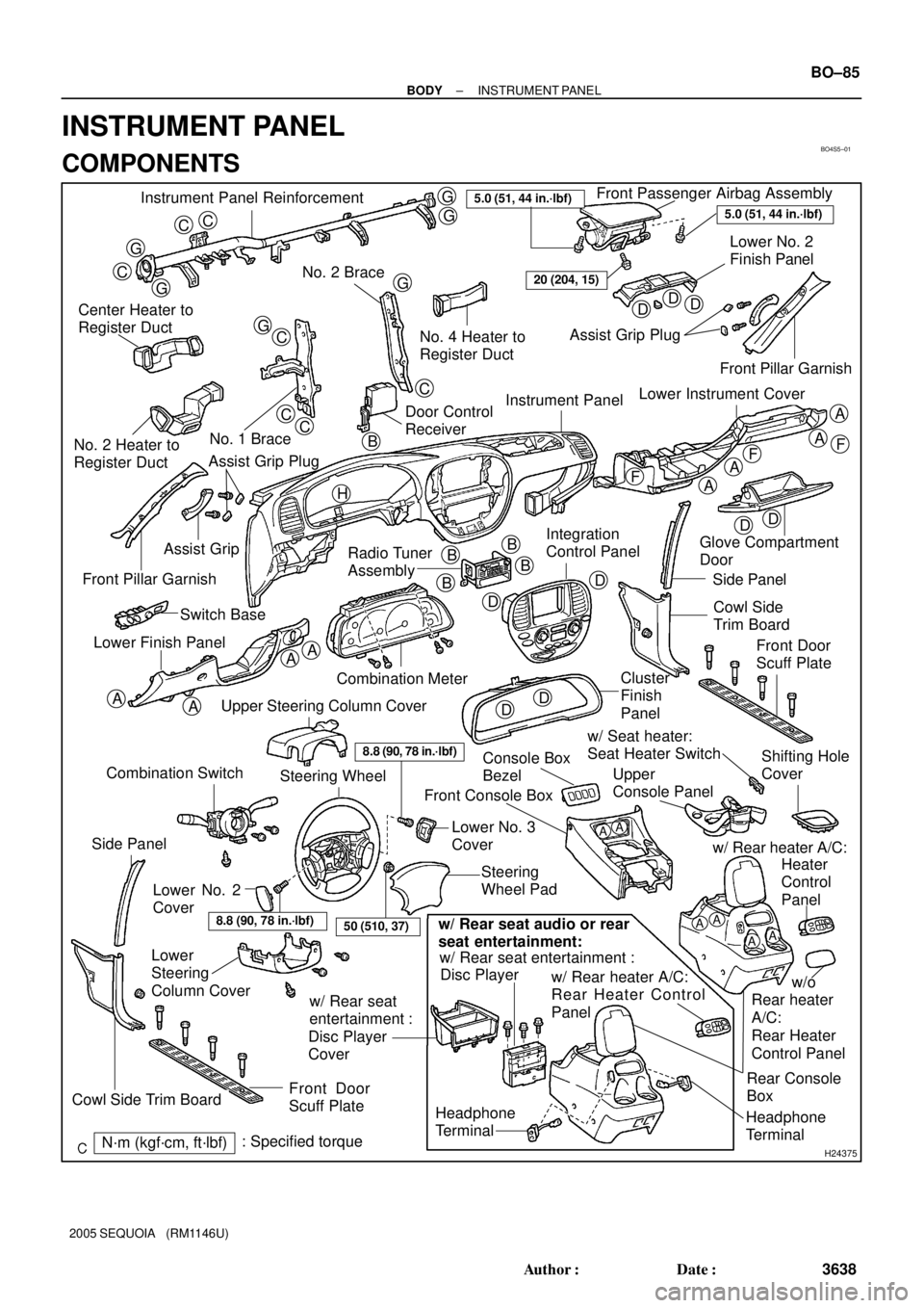
BO4S5±01
H24375
Instrument Panel ReinforcementFront Passenger Airbag Assembly
Lower No. 2
Finish Panel
No. 2 Brace
Center Heater to
Register Duct
No. 1 Brace
No. 2 Heater to
Register DuctNo. 4 Heater to
Register DuctAssist Grip Plug
Instrument Panel
Radio Tuner
Assembly Assist Grip
Front Pillar Garnish
Combination Meter Switch Base
Lower Finish PanelGlove Compartment
Door
Side Panel
Cowl Side
Trim Board
Cluster
Finish
Panel
Console Box
BezelUpper
Console Panel w/ Seat heater:
Seat Heater Switch
Steering
Wheel Pad Front Console Box
Lower
Steering
Column Cover
Front Door
Scuff Plate
N´m (kgf´cm, ft´lbf): Specified torque
CC
G
G
C
G
G
G
GC
CC
C
DDD
DD
A
A
A
A
AA
AA
F
FF
DD
D
DB
BB
B
5.0 (51, 44 in.´lbf)
20 (204, 15)
A
A
Headphone
Terminal
8.8 (90, 78 in.´lbf)
Lower No. 2
CoverLower No. 3
Cover
AAAA
Headphone
TerminalRear Console
Box w/ Rear seat entertainment :
w/ Rear heater A/C:
Rear Heater Control
Panel
w/ Rear seat
entertainment :
Disc Player
Coverw/ Rear heater A/C:
Disc Player
w/o
Rear heater
A/C:
Rear Heater
Control PanelHeater
Control
Panel
w/ Rear seat audio or rear
seat entertainment:
8.8 (90, 78 in.´lbf)
Steering Wheel
Upper Steering Column Cover
Front Door
Scuff Plate
Side Panel
Cowl Side Trim Board
5.0 (51, 44 in.´lbf)
Integration
Control Panel
Combination Switch
50 (510, 37)
Front Pillar Garnish
Lower Instrument Cover
Shifting Hole
Cover
Door Control
Receiver
Assist Grip Plug
H
B
± BODYINSTRUMENT PANEL
BO±85
3638 Author�: Date�:
2005 SEQUOIA (RM1146U)
INSTRUMENT PANEL
COMPONENTS
Page 3647 of 4323
H21026
Instrument Panel
Center Bracket
F
No. 5 Heater to Register DuctNo. 2 Register No. 3 Heater to Register Duct
E
Center Stay
F
F
No. 1 Register
F
FE
E
EE
E
Side Defroster
Nozzle Duct BO±86
± BODYINSTRUMENT PANEL
3639 Author�: Date�:
2005 SEQUOIA (RM1146U)
Page 3651 of 4323

H11174: 4 Clips
H11372
3 Clips
H11177
2 Clips
H16769
5 Clips
H24384
BO±90
± BODYINSTRUMENT PANEL
3643 Author�: Date�:
2005 SEQUOIA (RM1146U)
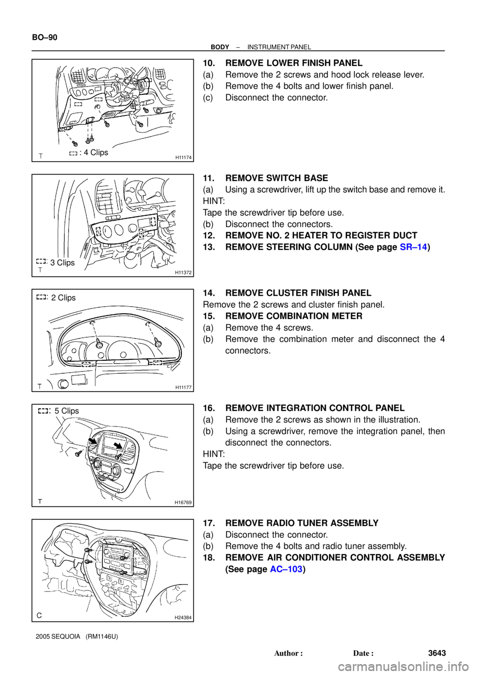
10. REMOVE LOWER FINISH PANEL
(a) Remove the 2 screws and hood lock release lever.
(b) Remove the 4 bolts and lower finish panel.
(c) Disconnect the connector.
11. REMOVE SWITCH BASE
(a) Using a screwdriver, lift up the switch base and remove it.
HINT:
Tape the screwdriver tip before use.
(b) Disconnect the connectors.
12. REMOVE NO. 2 HEATER TO REGISTER DUCT
13. REMOVE STEERING COLUMN (See page SR±14)
14. REMOVE CLUSTER FINISH PANEL
Remove the 2 screws and cluster finish panel.
15. REMOVE COMBINATION METER
(a) Remove the 4 screws.
(b) Remove the combination meter and disconnect the 4
connectors.
16. REMOVE INTEGRATION CONTROL PANEL
(a) Remove the 2 screws as shown in the illustration.
(b) Using a screwdriver, remove the integration panel, then
disconnect the connectors.
HINT:
Tape the screwdriver tip before use.
17. REMOVE RADIO TUNER ASSEMBLY
(a) Disconnect the connector.
(b) Remove the 4 bolts and radio tuner assembly.
18. REMOVE AIR CONDITIONER CONTROL ASSEMBLY
(See page AC±103)
Page 3652 of 4323

H16202
H11371
H24860
4 Clips
H16748
6 Clips
± BODYINSTRUMENT PANEL
BO±91
3644 Author�: Date�:
2005 SEQUOIA (RM1146U)
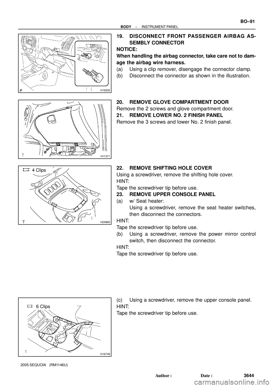
19. DISCONNECT FRONT PASSENGER AIRBAG AS-
SEMBLY CONNECTOR
NOTICE:
When handling the airbag connector, take care not to dam-
age the airbag wire harness.
(a) Using a clip remover, disengage the connector clamp.
(b) Disconnect the connector as shown in the illustration.
20. REMOVE GLOVE COMPARTMENT DOOR
Remove the 2 screws and glove compartment door.
21. REMOVE LOWER NO. 2 FINISH PANEL
Remove the 3 screws and lower No. 2 finish panel.
22. REMOVE SHIFTING HOLE COVER
Using a screwdriver, remove the shifting hole cover.
HINT:
Tape the screwdriver tip before use.
23. REMOVE UPPER CONSOLE PANEL
(a) w/ Seat heater:
Using a screwdriver, remove the seat heater switches,
then disconnect the connectors.
HINT:
Tape the screwdriver tip before use.
(b) Using a screwdriver, remove the power mirror control
switch, then disconnect the connector.
HINT:
Tape the screwdriver tip before use.
(c) Using a screwdriver, remove the upper console panel.
HINT:
Tape the screwdriver tip before use.
Page 3653 of 4323

H16749
H18899
H243734 Claws
H16751
2 Clips
H21029
BO±92
± BODYINSTRUMENT PANEL
3645 Author�: Date�:
2005 SEQUOIA (RM1146U)
24. REMOVE REAR CONSOLE BOX
(a) w/ Rear heater A/C:
Using a screwdriver, remove the rear heater control pan-
el, then disconnect the connector.
HINT:
Tape the screwdriver tip before use.
(b) w/ Headphone terminal.
Using a screwdriver, remove the headphone terminal and
the connector.
(c) w/ Rear seat entertainment:
(1) Remove the disc bracket.
(2) Remove the 3 bolts and disc player.
(3) Disconnect the connector.
(d) Remove the 4 bolts and rear console box.
25. REMOVE CONSOLE BOX BEZEL
(a) Using a screwdriver, remove the console box bezel.
HINT:
Tape the screwdriver tip before use.
(b) Disconnect the connectors.
26. REMOVE FRONT CONSOLE BOX
Remove the 2 bolts, 2 clips and front console box.
27. REMOVE LOWER INSTRUMENT COVER
(a) Remove the 4 bolts and 3 screws.
(b) Using a screwdriver, remove the lower instrument cover.
HINT:
Tape the screwdriver tip before use.
28. REMOVE PASSENGER AIRBAG ASSEMBLY
(a) Remove the 2 bolts holding the front passenger airbag
assembly and instrument panel.
Torque: 5.0 N´m (51 kgf´cm, 44 in.´lbf)
Page 3654 of 4323
H11181
± BODYINSTRUMENT PANEL
BO±93
3646 Author�: Date�:
2005 SEQUOIA (RM1146U)
(b) Remove the bolt holding the front passenger airbag as-
sembly and instrument panel reinforcement.
Torque: 20 N´m (204 kgf´cm, 15 ft.´lbf)
CAUTION:
�Do not store the front passenger airbag assembly
with the airbag deployment side facing down.
�Never disassemble the front passenger airbag as-
sembly.
29. REMOVE NO. 4 HEATER TO REGISTER DUCT
30. REMOVE INSTRUMENT PANEL
(a) Remove the nut.
(b) Disconnect the connectors and remove the instrument
panel.