Page 3781 of 4323
I21390
X10
AC3HC±02
I21395
Marking A
B
I21396Marking B AC±46
± AIR CONDITIONINGREAR A/C UNIT
3773 Author�: Date�:
2005 SEQUOIA (RM1146U)
REASSEMBLY
1. ASSEMBLE REAR A/C UNIT
(a) Install the insulator and heater radiator.
(b) Install the shaft and sliding door.
(c) Assemble the A/C unit and install the 10 screws.
(d) Install the blower case, clamp and 2 screws.
2. INSTALL AIR OUTLET SERVOMOTOR
(a) Align marking A on the grid part of the case with the side
of sliding door rack B.
(b) Install the servomotor with the 3 screws.
HINT:
The projection on the gear (marking B) shall be positioned verti-
cally.
3. INSTALL EVAPORATOR
4. INSTALL EXPANSION VALVE
5. INSTALL WATER VALVE
6. INSTALL THERMISTOR
7. INSTALL POWER TRANSISTOR
8. INSTALL BLOWER MOTOR
Page 3783 of 4323
AC1KT±05
I21425
Lower LH
Finish Panel
Cooling Unit
Blower Unit
Air Inlet Servomotor
Blower Motor
Heater to Register
Duct No. 4
Front Door Scuff Plate RH
Blower Unit Case
Lower Cover
Lower No. 2
Finish Panel
Glove Compartment Door
Cowl Side
Trim RH
Front
Console
Box
Console
Upper Panel
Rear
Console Box AC±48
± AIR CONDITIONINGBLOWER UNIT
3775 Author�: Date�:
2005 SEQUOIA (RM1146U)
BLOWER UNIT
COMPONENTS
Page 3814 of 4323
AC3HL±02
I21369
I21370
I21371
± AIR CONDITIONINGWATER VALVE
AC±79
3806 Author�: Date�:
2005 SEQUOIA (RM1146U)
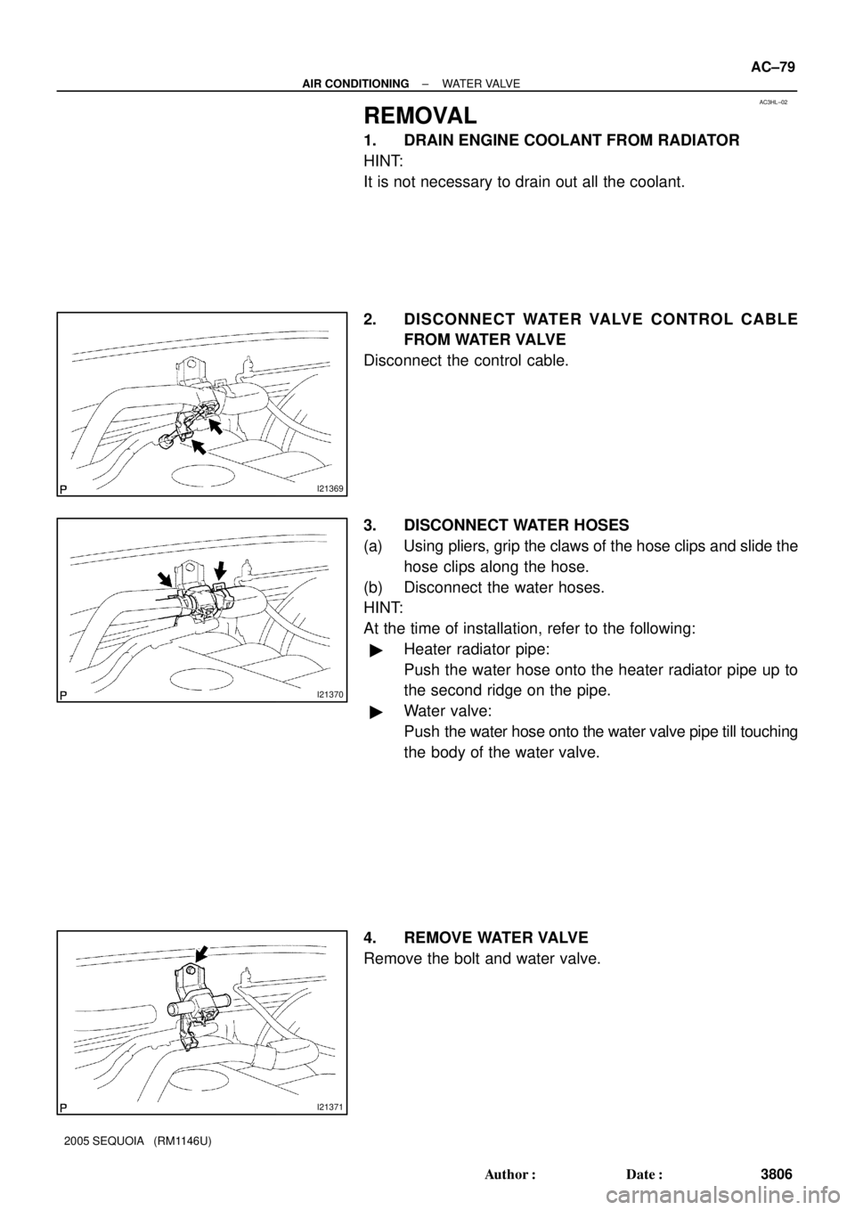
REMOVAL
1. DRAIN ENGINE COOLANT FROM RADIATOR
HINT:
It is not necessary to drain out all the coolant.
2. DISCONNECT WATER VALVE CONTROL CABLE
FROM WATER VALVE
Disconnect the control cable.
3. DISCONNECT WATER HOSES
(a) Using pliers, grip the claws of the hose clips and slide the
hose clips along the hose.
(b) Disconnect the water hoses.
HINT:
At the time of installation, refer to the following:
�Heater radiator pipe:
Push the water hose onto the heater radiator pipe up to
the second ridge on the pipe.
�Water valve:
Push the water hose onto the water valve pipe till touching
the body of the water valve.
4. REMOVE WATER VALVE
Remove the bolt and water valve.
Page 3818 of 4323
AC3HP±02
I21372
± AIR CONDITIONINGBLOWER MOTOR LINEAR CONTROLLER
AC±83
3810 Author�: Date�:
2005 SEQUOIA (RM1146U)
BLOWER MOTOR LINEAR
CONTROLLER
INSPECTION
1. REMOVE GLOVE COMPARTMENT PARTS
2. REMOVE LOWER NO. 2 FINISH PANEL
3. REMOVE LOWER CENTER COVER
4. REMOVE LOWER LH FINISH PANEL
5. REMOVE NO. 4 HEATER TO REGISTER DUCT
6. REMOVE BLOWER MOTOR LINEAR CONTROLLER
(a) Disconnect the connector.
(b) Remove the 2 screws and blower motor linear controller.
7. INSPECT BLOWER MOTOR LINEAR CONTROLLER
(See page DI±2374)
8. INSTALL BLOWER MOTOR LINEAR CONTROLLER
(a) Install the blower motor linear controller with the 2 screws.
(b) Connect the connector.
9. INSTALL NO. 4 HEATER TO REGISTER DUCT
10. INSTALL LOWER LH FINISH PANEL
11. INSTALL LOWER CENTER COVER
12. INSTALL LOWER NO. 2 FINISH PANEL
13. INSTALL GLOVE COMPARTMENT PARTS
Page 3822 of 4323
AC3HS±02
I21375
I03738
± AIR CONDITIONINGTHERMISTOR (for Rear A/C)
AC±87
3814 Author�: Date�:
2005 SEQUOIA (RM1146U)
THERMISTOR (for Rear A/C)
INSPECTION
1. REMOVE SIDE HEATER COVER
2. REMOVE THERMISTOR
(a) Disconnect the connector and connector clamp.
(b) Using a screwdriver, pull out the sensor.
HINT:
Tape the screwdriver tip before use.
(c) Release the 2 claws and remove the sensor from the
bracket plate.
3. INSPECT THERMISTOR (See page DI±2330)
4. INSTALL THERMISTOR
5. INSTALL SIDE HEATER COVER
Page 3830 of 4323
I21427
Heater RelayCondenser
Fan Relay
Magnetic
Clutch Relay
Rear Heater Relay
AC3HU±02
N02832
1
2 3
5
1
23
5
4
4
Z18060
23
15
5
13
2
± AIR CONDITIONINGRELAY
AC±95
3822 Author�: Date�:
2005 SEQUOIA (RM1146U)
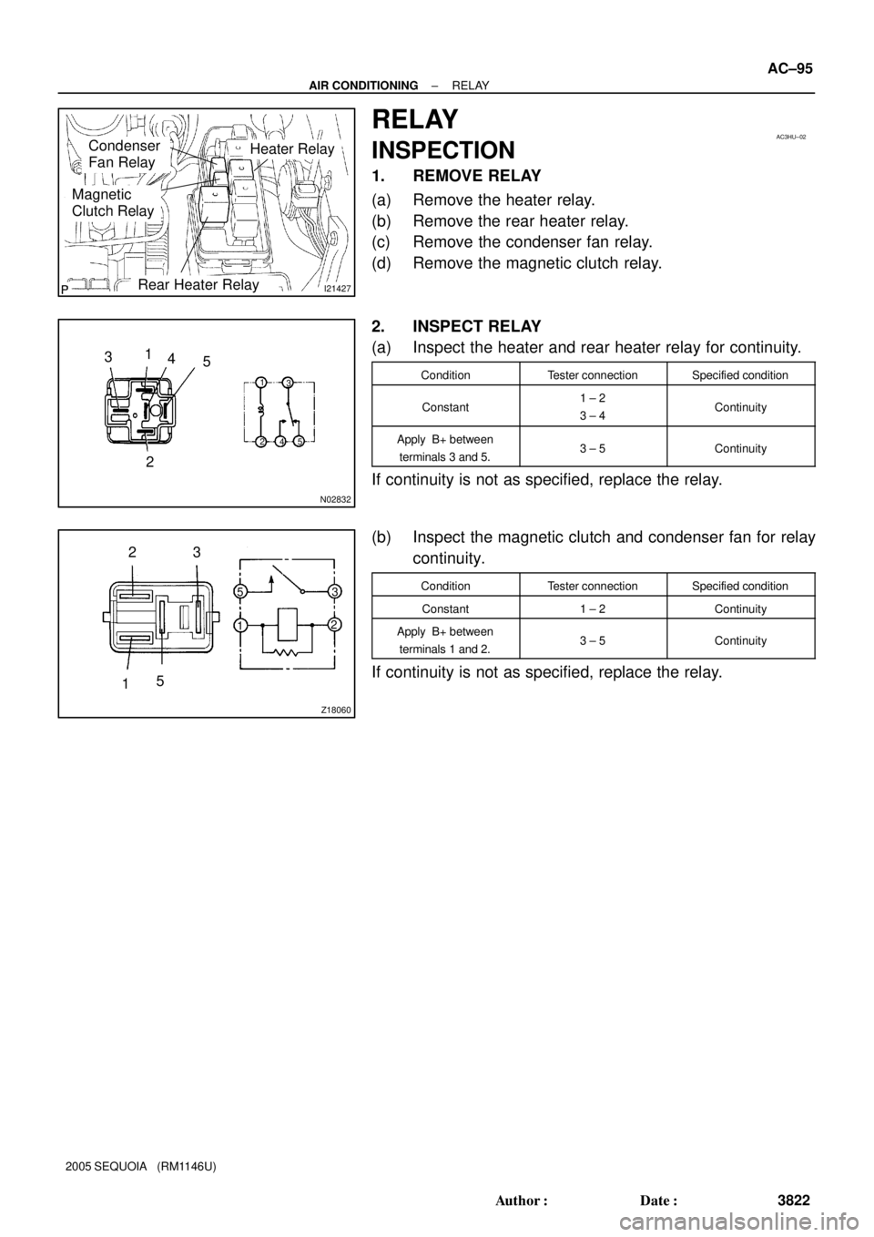
RELAY
INSPECTION
1. REMOVE RELAY
(a) Remove the heater relay.
(b) Remove the rear heater relay.
(c) Remove the condenser fan relay.
(d) Remove the magnetic clutch relay.
2. INSPECT RELAY
(a) Inspect the heater and rear heater relay for continuity.
ConditionTester connectionSpecified condition
Constant1 ± 2
3 ± 4Continuity
Apply B+ between
terminals 3 and 5.3 ± 5Continuity
If continuity is not as specified, replace the relay.
(b) Inspect the magnetic clutch and condenser fan for relay
continuity.
ConditionTester connectionSpecified condition
Constant1 ± 2Continuity
Apply B+ between
terminals 1 and 2.3 ± 5Continuity
If continuity is not as specified, replace the relay.
Page 3837 of 4323
AC3I1±03
I21397
Center Cluster
Integration Panel
Heater
Control
Housing
A/C Amplifier
Seat Belt Indicator Circuit
BulbBulb
Bulb
Knob
Knob
Knob
Integration Panel
Knob
AC±102± AIR CONDITIONINGAIR CONDITIONER CONTROL ASSEMBLY (Center
Cluster Integration)
3829 Author�: Date�:
2005 SEQUOIA (RM1146U)
AIR CONDITIONER CONTROL ASSEMBLY (Center Cluster
Integration)
COMPONENTS
Page 3839 of 4323
I21399
AC3HX±03
I21400
I21401
I21402
I21417
AC±104± AIR CONDITIONINGAIR CONDITIONER CONTROL ASSEMBLY (Center
Cluster Integration)
3831 Author�: Date�:
2005 SEQUOIA (RM1146U)
DISASSEMBLY
1. REMOVE BULBS
Remove the 3 bulbs.
2. REMOVE A/C AMPLIFIER
(a) Remove the 7 screws and heater control housing.
(b) Disconnect the 2 connectors.
(c) Remove the 3 screws and A/C amplifier.
(d) Remove the passenger seat belt indicator circuit.
3. REMOVE INTEGRATION CIRCUIT
(a) Remove the 2 knobs.
(b) Remove the 2 nuts and 2 washers.