Page 2631 of 4323
A02871
A23344
A23345
EM±44
± ENGINE MECHANICALCYLINDER HEAD
2623 Author�: Date�:
2005 SEQUOIA (RM1146U)
(b) Lift the cylinder head from the dowels on the cylinder
block, and place the 2 cylinder heads on wooden blocks
on a bench.
HINT:
If the cylinder head is difficult to lift off, pry between the cylinder
head and cylinder block with a screwdriver.
NOTICE:
�Be careful not to damage the contact surfaces of the
cylinder head and cylinder block.
�The cylinder head should not be tilted so as to secure
the valve lifter. If the cylinder head is tilted, remove
the valve lifter and check that the adjusting shim is
set correctly.
29. REMOVE RH EXHAUST MANIFOLD FROM CYLINDER
HEAD
(a) Remove the 4 bolts and heat insulator.
(b) Remove the 8 nuts, exhaust manifold and gasket.
30. REMOVE LH EXHAUST MANIFOLD FROM CYLINDER
HEAD
(a) Remove the 4 bolts and heat insulator.
(b) Remove the 8 nuts, exhaust manifold and gasket.
Page 2667 of 4323

A09151
A08905
A08907
EM±80
± ENGINE MECHANICALENGINE UNIT (2WD)
2659 Author�: Date�:
2005 SEQUOIA (RM1146U)
(d) Disconnect the hose clamp for the PS air hose.
(e) Disconnect the PS air hose from the upper intake man-
ifold.
(f) Disconnect the 2 heater hoses.
(g) Disconnect the ground strap from the cowl panel.
(h) Disconnect the fuel inlet hose and clamps.
(i) Disconnect the fuel return hose and clamp.
(j) Disconnect the air inlet hose from the charcoal canister.
(k) Disconnect the EVAP hose from the charcoal canister.
(l) w/o Hydraulic brake booster:
Disconnect the brake booster tube.
11. REMOVE FRONT EXHAUST PIPES
(See page EM±126)
12. REMOVE PROPELLER SHAFT (See page PR±3)
13. REMOVE FRONT STABILIZER BAR
(See page SA±91)
14. DISCONNECT POWER STEERING GEAR PIPES
Disconnect the pressure feed tube, turn tube and pressure
tubes from the PS gear assembly.
(See page SR±40, SR±41)
15. REMOVE TRANSMISSION CONTROL CABLE
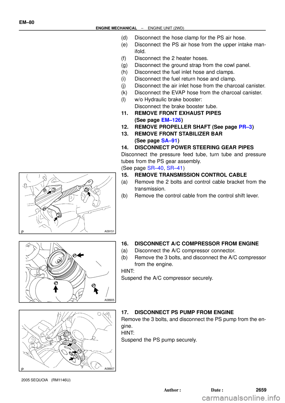
(a) Remove the 2 bolts and control cable bracket from the
transmission.
(b) Remove the control cable from the control shift lever.
16. DISCONNECT A/C COMPRESSOR FROM ENGINE
(a) Disconnect the A/C compressor connector.
(b) Remove the 3 bolts, and disconnect the A/C compressor
from the engine.
HINT:
Suspend the A/C compressor securely.
17. DISCONNECT PS PUMP FROM ENGINE
Remove the 3 bolts, and disconnect the PS pump from the en-
gine.
HINT:
Suspend the PS pump securely.
Page 2680 of 4323

B07536
Disconnect
A08905
A08907
A08936
± ENGINE MECHANICALENGINE UNIT (4WD)
EM±93
2672 Author�: Date�:
2005 SEQUOIA (RM1146U)
(f) Disconnect the engine wire from the engine wire bracket
and remove the 2 nuts, bolt and bracket.
(g) Pull out the engine wire from the cowl panel.
14. DISCONNECT HOSES, WIRES, CONNECTORS,
CLAMPS, GROMMET AND CABLES
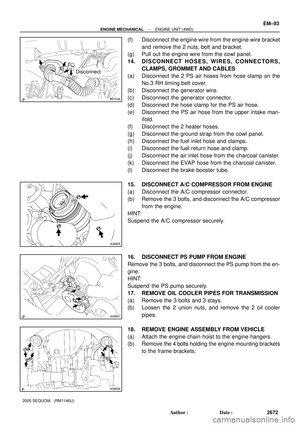
(a) Disconnect the 2 PS air hoses from hose clamp on the
No.3 RH timing belt cover.
(b) Disconnect the generator wire.
(c) Disconnect the generator connector.
(d) Disconnect the hose clamp for the PS air hose.
(e) Disconnect the PS air hose from the upper intake man-
ifold.
(f) Disconnect the 2 heater hoses.
(g) Disconnect the ground strap from the cowl panel.
(h) Disconnect the fuel inlet hose and clamps.
(i) Disconnect the fuel return hose and clamp.
(j) Disconnect the air inlet hose from the charcoal canister.
(k) Disconnect the EVAP hose from the charcoal canister.
(l) Disconnect the brake booster tube.
15. DISCONNECT A/C COMPRESSOR FROM ENGINE
(a) Disconnect the A/C compressor connector.
(b) Remove the 3 bolts, and disconnect the A/C compressor
from the engine.
HINT:
Suspend the A/C compressor securely.
16. DISCONNECT PS PUMP FROM ENGINE
Remove the 3 bolts, and disconnect the PS pump from the en-
gine.
HINT:
Suspend the PS pump securely.
17. REMOVE OIL COOLER PIPES FOR TRANSMISSION
(a) Remove the 3 bolts and 3 stays.
(b) Loosen the 2 union nuts, and remove the 2 oil cooler
pipes.
18. REMOVE ENGINE ASSEMBLY FROM VEHICLE
(a) Attach the engine chain hoist to the engine hangers.
(b) Remove the 4 bolts holding the engine mounting brackets
to the frame brackets.
Page 2743 of 4323

SF1XD±01
± SFISFI SYSTEM
SF±1
2735 Author�: Date�:
2005 SEQUOIA (RM1146U)
SFI SYSTEM
PRECAUTION
HINT:
All DTCs retained in the ECM will be erased when the negative
(±) terminal cable is removed from the battery.
If necessary, read the DTC before removing the negative (±)
terminal cable from the battery.
1. BEFORE WORKING ON FUEL SYSTEM,
DISCON-
NECT CABLE FROM NEGATIVE (±) BATTERY TERMI-
NAL
2. DO NOT SMOKE OR WORK NEAR AN OPEN FLAME
WHEN WORKING ON FUEL SYSTEM
3. KEEP GASOLINE AWAY FROM RUBBER OR
LEATH-
ER PARTS
4. MAINTENANCE PRECAUTIONS
(a) To prevent engine misfire, these precautions should be
taken.
(1) Check the battery terminals are proper connected.
(2) After repair, check that the ignition coil terminals
and all other ignition system lines are reconnected
securely.
(3) When cleaning the engine compartment, be espe-
cially careful to protect the electrical system from
water.
(b) Observe the following when handling the air fuel ratio
sensors and oxygen sensor.
(1) Do not drop the sensor or hit it against another ob-
ject.
(2) The sensor should be free from any contact with wa-
ter.
5. IF VEHICLE IS EQUIPPED WITH MOBILE RA-
DIO
SYSTEM (HAM, CB, ETC.)
If the vehicle is equipped with a mobile communication system,
refer to the precaution in the IN section.
6. AIR INDUCTION SYSTEM
(a) Removal of the engine oil dipstick, oil filler cap, PCV hose,
may break the engine.
(b) Disconnection, looseness or cracks in the parts of the air
induction system between the throttle body and cylinder
head may result in air suction and break the engine.
7. ELECTRONIC CONTROL SYSTEM
(a) Before removing SFI wiring connectors, terminals, first
disconnect the power by turning the ignition switch off or
disconnecting the negative (±) terminal cable from the
battery.
HINT:
Be sure to check DTCs before disconnecting the negative (±)
terminal cable from the battery.
Page 2746 of 4323

B11683
Quick Type
Push
B12520
Quick Type
Pull
B17533
Quick Type
Install
B06584
Metallic Type
O±Ring Retainer Pipe
Nylon Tube
Housing
B09688
Metallic Type
SST
SF±4
± SFISFI SYSTEM
2738 Author�: Date�:
2005 SEQUOIA (RM1146U)
(f) Observe the following when connecting the fuel tube con-
nector (quick type):
(1) Check if there is any damage or foreign objects in
the connected part of the pipe.
(2) Match the axis of the connector with the axis of the
pipe, and push into the connector until a ºclickº
sound is heard. If the connection is tight, apply a
small amount of fresh engine oil on the tip of the
pipe.
(3) After finishing the connection, pull the pipe and the
connector to ensure it is secure.
(4) Check to make sure no fuel leak is present.
If the result is not specified, repair or replace.
(5) Install the fuel pipe clamp to the connector.
(6) Check to make sure no fuel leak is present.
If the result is not specified, repair or replace.
(g) Observe the following when disconnecting the fuel tube
connector (metallic type):
HINT:
The structure of the metallic connector is shown on the left.
(1) Check if there is any dirt in the pipe and around the
connector before disconnecting the fuel tube con-
nector. If necessary, clean the dirt away.
(2) Assemble SST to the connecting part, as shown in
the illustration.
SST 09268±21010
Page 2747 of 4323

B10035
Metallic Type
SST
Insert Retainer
(at 4 places)
B10036
Metallic Type
Pull Connector
B10485
Metallic Type
Push
B10485
Metallic Type
Pull
± SFISFI SYSTEM
SF±5
2739 Author�: Date�:
2005 SEQUOIA (RM1146U)
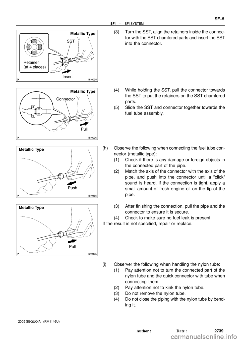
(3) Turn the SST, align the retainers inside the connec-
tor with the SST chamfered parts and insert the SST
into the connector.
(4) While holding the SST, pull the connector towards
the SST to put the retainers on the SST chamfered
parts.
(5) Slide the SST and connector together towards the
fuel tube assembly.
(h) Observe the following when connecting the fuel tube con-
nector (metallic type):
(1) Check if there is any damage or foreign objects in
the connected part of the pipe.
(2) Match the axis of the connector with the axis of the
pipe, and push into the connector until a ºclickº
sound is heard. If the connection is tight, apply a
small amount of fresh engine oil on the tip of the
pipe.
(3) After finishing the connection, pull the pipe and the
connector to ensure it is secure.
(4) Check to make sure no fuel leak is present.
If the result is not specified, repair or replace.
(i) Observer the following when handling the nylon tube:
(1) Pay attention not to turn the connected part of the
nylon tube and the quick connector with tube when
connecting them.
(2) Pay attention not to kink the nylon tube.
(3) Do not remove the nylon tube.
(4) Do not close the piping with the nylon tube by bend-
ing it.
Page 2762 of 4323
SF±20
± SFIFUEL PUMP
2754 Author�: Date�:
2005 SEQUOIA (RM1146U)
NOTICE:
�Check that there are no scratches or foreign objects
on the connecting part.
�Check that the fuel tube joint is inserted securely.
�Check that the tube joint clip is on the collar of the fuel
tube joint.
�After installing the tube joint clip, check that the fuel
tube joint has not been pulled off.
3. CHECK FOR FUEL LEAKS
4. INSTALL FUEL TANK ASSEMBLY (See page SF±36)
Page 2871 of 4323

SPARK TEST
Replace the crankshaft position sensor.
CHECK CONNECTION OF IGNITION COIL
CONNECTOR
CHECK RESISTANCE OF CRANKSHAFT POSITION
Resistance:Cold Hot
CHECK IGT SIGNAL FROM ECM
(See page DI±221)
REPAIR WIRING BETWEEN IGNITION COIL
AND ECM
Connect securely.
Check wiring between ignition switch
to ignition coil (with igniter).
Check ECM (See page IN±35)
NG
OK
OK
OKBAD
BAD
BAD
CHANGE IT TO NORMAL IGNITION COIL (WITH
IGNITER) AND PERFORM SPARK TEST AGAIN
OKReplace the ignition coil (with igniter).
NO
OK
985 ± 1,600 W1,265 ± 1,890 WBAD
CHECK POWER SUPPLY TO IGNITION COIL (WITH
1. Turn ignition switch to ON.
2. Check that there is battery voltage at ignition coil positive (+)
terminal.IGNITER)
CHECK TDC
NG
SENSOR (See page IG±12)
B03198
16 mm Plug Wrench
IG±2
± IGNITIONIGNITION SYSTEM
2863 Author�: Date�:
2005 SEQUOIA (RM1146U)
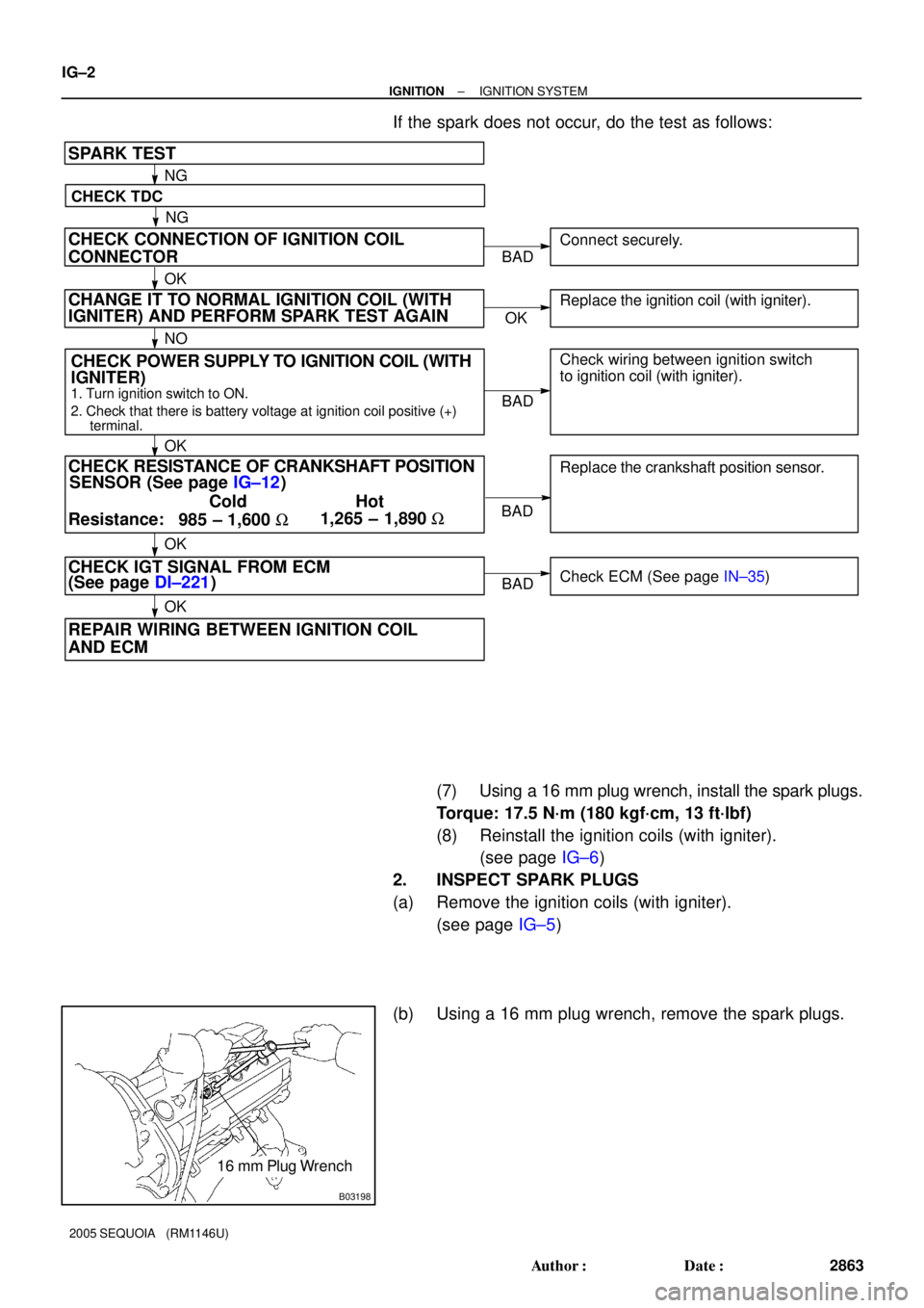
If the spark does not occur, do the test as follows:
(7) Using a 16 mm plug wrench, install the spark plugs.
Torque: 17.5 N´m (180 kgf´cm, 13 ft´lbf)
(8) Reinstall the ignition coils (with igniter).
(see page IG±6)
2. INSPECT SPARK PLUGS
(a) Remove the ignition coils (with igniter).
(see page IG±5)
(b) Using a 16 mm plug wrench, remove the spark plugs.