Page 2990 of 4323

12. INSPECT FOUR WHEEL DRIVE CONTROL ECU
(a) Connect the wire harness side connector to the four")
F19566
TR±44
± TRANSFERONE TOUCH 2±4 SELECTOR SYSTEM
2982 Author�: Date�:
2005 SEQUOIA (RM1146U)
12. INSPECT FOUR WHEEL DRIVE CONTROL ECU
(a) Connect the wire harness side connector to the four wheel drive control ECU and inspect the wire har-
ness side connector from the back, as shown.
STANDARD VALUE OF ECU TERMINAL
Terminals (Symbols)ConditionSTD Voltage (V)
3 (HM1) ± 4 (HM2)
�Ignition switch ON
�Four wheel drive control switch ºH4º position " Four wheel drive control switch
ºL4º position
10 to 14 " 2 or less
or
4 (HM2) ± 3 (HM1)
�Ignition switch ON
�Four wheel drive control switch ºL4º position " Four wheel drive control switch
ºH4º position
or
0 (0.5 s) to 14 (50 ms)
pulse generation
2 (TM1) ± 1 (TM2)
�Ignition switch ON
�Differential lock switch is in ºOFFº position
�Four wheel drive control switch ºH2º position " Four wheel drive control switch
ºH4º position
10 to 14 " 2 or less
or
1 (TM2) ± 2 (TM1)
�Ignition switch ON
�Keep pressing the differential lock switch for approx. 2 seconds to turn it ON
�Four wheel drive control switch ºH4ºor ºL4º position " Four wheel drive control
switch ºH2º position
or
0 (0.5 s) to 14 (50 ms)
pulse generation
5 (DM1) ± 6 (DM2)�Ignition switch ON
�A.D.D. FREE "A.D.D. LOCK10 to 14 " 2 or less
or
6 (DM2) ± 5 (DM2)�Ignition switch ON
�A.D.D. LOCK "A.D.D. FREE
or
0 (0.5 s) to 14 (50 ms)
pulse generation
4 (HM2) ± 7 (GND)
�Ignition switch ON
�Four wheel drive control switch ºH4º position " Four wheel drive control switch
ºL4º position
2 or less " 10 to 14
7 (GND) ± Body ground�Ignition switch OFFContinuity
12 (IG) ± 7 (GND)�Ignition switch ON10 to 14
18 (DL2) ± 7 (GND)�Ignition switch ON
�A.D.D. LOCK "A.D.D. FREE0.88 or less " 10 to 14
19 (DL1) ± 7 (GND)�Ignition switch ON
�A.D.D. FREE "A.D.D. LOCK0.88 or less " 10 to 14
23 (HL1) ± 7 (GND)
�Ignition switch ON
�Four wheel drive control switch ºH4º position " Four wheel drive control switch
ºL4º position
10 to 14 " 1.5 or less
25 (2±4) ± 7 (GND)
�Ignition switch ON
�Four wheel drive control switch ºL4º position " Four wheel drive control switch
ºH2º or ºH4º position
10 to 14 " 1.5 or less
26 (SPD) ± 7 (GND)�During drivingPulse generation
Page 3021 of 4323

F19826
Rim
Sensor
Cap
Nut
WasherGrommet
F19827
Area for the sensorRim
Rim rotating
direction
Rim rotating
directionRim
Area for the sensor
Mount tool of the mounting machine
Mount tool of the mounting machine
± SUSPENSION AND AXLETIRE PRESSURE MONITOR VALVE
SA±17
3013 Author�: Date�:
2005 SEQUOIA (RM1146U)
�If installed in the reverse direction, the tire pressure
monitor valve may be damaged or fail to transmit sig-
nals when running at high speed.
�If installing a new tire pressure monitor valve, write
down the ID number before installation.
�It is necessary to registor an ID in the ECU after instal-
lation (See page DI±805).
(b) Install the washer on the tire pressure monitor valve from
the rim side and tighten with a nut.
Torque: 4.0 NVm (41 kgfVcm, 35 in.Vlbf)
NOTICE:
�Check that there is no foreign matter on the washer
and nut.
�If the tire pressure monitor valve is removed when the
tire is removed for replacement, check that there is no
damage or cuts, and no foreign matter such as mud,
dirt or sand attached to the grommet. Replace the
grommet with a new one if any of the defects men-
tioned above are found.
�Check that there is no oil, water or lubricant around
the rim hole, tire pressure monitor valve, washer and
nut. Failing to do so may result in improper installa-
tion.
(c) After the tire is inflated, the valve nut may be loose. Re-
tighten the nut to the specified torque and then check for
air leaks with soapy water.
Torque: 4.0 NVm (41 kgfVcm, 35 in.Vlbf)
(d) Set the wheel disc to the mounting machine and install the
lower tire bead. Position the main body of the sensor as
in the shaded area shown in the illustration.
NOTICE:
If the sensor is positioned outside this area, it generates in-
terference with the tire bead, causing possible damage to
the sensor.
(e) Install the upper bead.
NOTICE:
Make sure that the tire bead and tool do not interfere with
the main body of the sensor and that the sensor is not
clamped by the bead.
5. INSTALL FRONT WHEEL
Torque: 103 NVm (1,050 kgfVcm, 76 ftVlbf)
6. INSTALL REAR WHEEL
Torque: 103 NVm (1,050 kgfVcm, 76 ftVlbf)
7. INSPECT TIRE (See page SA±3)
8. REGISTRATION OF TRANSMITTED ID
(See page DI±805)
Page 3023 of 4323
SA2CU±01
F16852
Tire Pressure Monitor ECU
± SUSPENSION AND AXLETIRE PRESSURE MONITOR ECU
SA±19
3015 Author�: Date�:
2005 SEQUOIA (RM1146U)
TIRE PRESSURE MONITOR ECU
COMPONENTS
Page 3024 of 4323
SA2CV±01
F16822
F16822
SA±20
± SUSPENSION AND AXLETIRE PRESSURE MONITOR ECU
3016 Author�: Date�:
2005 SEQUOIA (RM1146U)
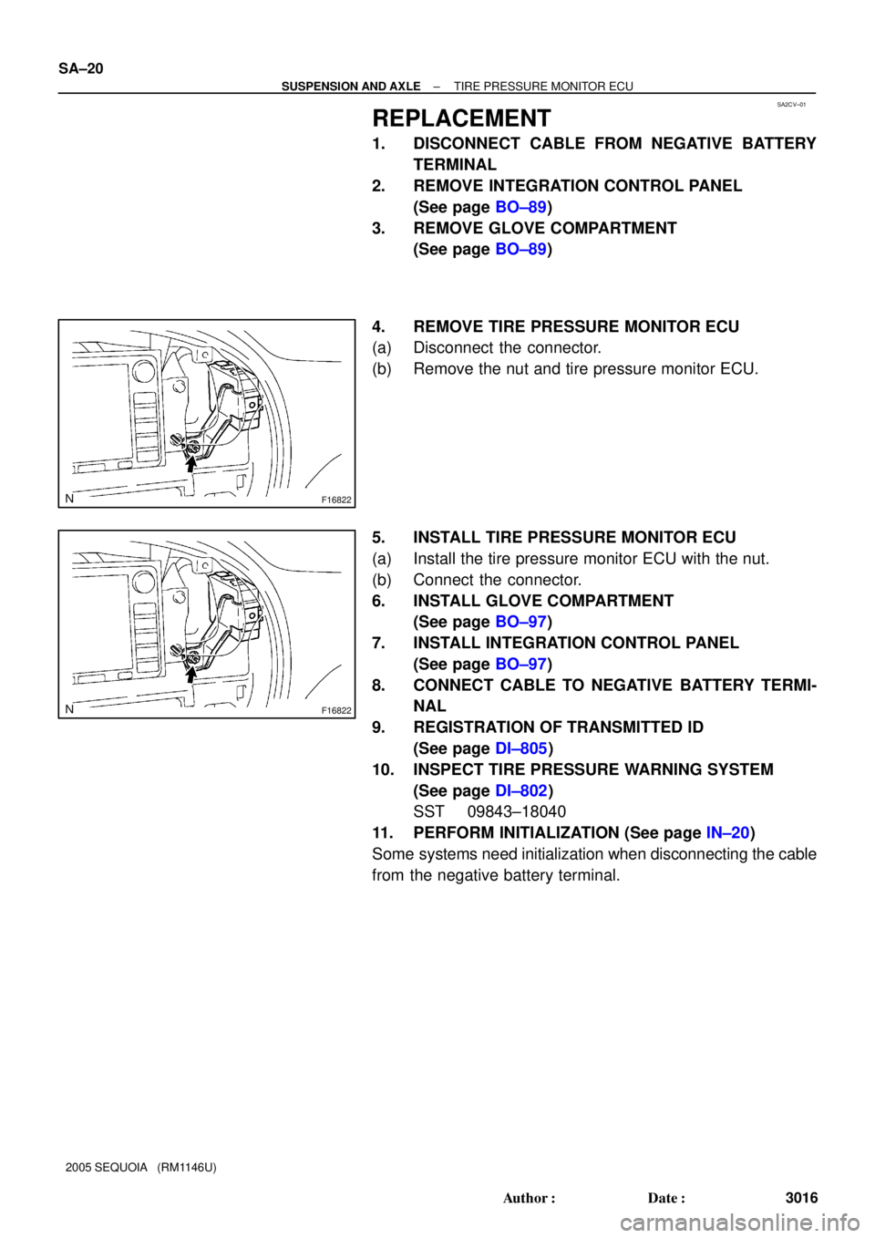
REPLACEMENT
1. DISCONNECT CABLE FROM NEGATIVE BATTERY
TERMINAL
2. REMOVE INTEGRATION CONTROL PANEL
(See page BO±89)
3. REMOVE GLOVE COMPARTMENT
(See page BO±89)
4. REMOVE TIRE PRESSURE MONITOR ECU
(a) Disconnect the connector.
(b) Remove the nut and tire pressure monitor ECU.
5. INSTALL TIRE PRESSURE MONITOR ECU
(a) Install the tire pressure monitor ECU with the nut.
(b) Connect the connector.
6. INSTALL GLOVE COMPARTMENT
(See page BO±97)
7. INSTALL INTEGRATION CONTROL PANEL
(See page BO±97)
8. CONNECT CABLE TO NEGATIVE BATTERY TERMI-
NAL
9. REGISTRATION OF TRANSMITTED ID
(See page DI±805)
10. INSPECT TIRE PRESSURE WARNING SYSTEM
(See page DI±802)
SST 09843±18040
11. PERFORM INITIALIZATION (See page IN±20)
Some systems need initialization when disconnecting the cable
from the negative battery terminal.
Page 3026 of 4323
SA23I±04
R13426
F07263
F07264
F07265
SA±22
± SUSPENSION AND AXLEFRONT AXLE HUB
3018 Author�: Date�:
2005 SEQUOIA (RM1146U)
REMOVAL
1. REMOVE FRONT WHEEL
2. REMOVE GREASE CAP
Using a screwdriver and hammer, remove the grease cap.
3. 4WD:
DISCONNECT DRIVE SHAFT
(a) Remove the cotter pin and lock cap.
(b) While applying the brakes, remove the lock nut.
4. DISCONNECT SPEED SENSOR AND WIRE HARNESS
CLAMP FROM STEERING KNUCKLE
Remove the 2 bolts and disconnect the speed sensor and wire
harness clamp from the steering knuckle.
5. REMOVE BRAKE CALIPER AND DISC
(a) Remove the bolt and brake line clamp from the steering
knuckle.
(b) Remove the 2 bolts, brake caliper and disc.
NOTICE:
Do not damage the brake tube.
(c) Support the brake caliper securely.
6. REMOVE SHOCK ABSORBER (See page SA±64)
7. DISCONNECT LOWER BALL JOINT
Remove the 4 bolts and disconnect the lower ball joint.
8. REMOVE STEERING KNUCKLE
(a) Remove the cotter pin and loosen the nut.
Page 3033 of 4323

FRONT WHEEL HUB BOLT
REPLACEMENT
1. REMOVE FRONT WHEEL
2. RE")
SA24P±03
F07264
R13372
SST
R13373WasherNut
± SUSPENSION AND AXLEFRONT WHEEL HUB BOLT
SA±29
3025 Author�: Date�:
2005 SEQUOIA (RM1146U)
FRONT WHEEL HUB BOLT
REPLACEMENT
1. REMOVE FRONT WHEEL
2. REMOVE BRAKE CALIPER AND DISC
(a) Remove the bolt and brake line clamp from the steering
knuckle.
(b) Remove the 2 bolts, brake caliper and disc.
(c) Support the brake caliper securely.
3. REMOVE HUB BOLT
Using SST and a screwdriver or an equivalent, remove the hub
bolt.
SST 09650±17011
4. INSTALL HUB BOLT
(a) Install a washer and nut to a new hub bolt as shown in the
illustration.
(b) Using a screwdriver or an equivalent to hold, install the
hub bolt by torquing the nut.
(c) Remove the nut and washer.
5. INSTALL BRAKE DISC AND CALIPER
(a) Install the brake disc, caliper and 2 bolts.
Torque: 123 N´m (1,250 kgf´cm, 90 ft´lbf)
(b) Install the brake line clamp to the steering knuckle with the
bolt.
Torque: 28 N´m (285 kgf´cm, 21 ft´lbf)
6. INSTALL FRONT WHEEL
Torque: 110 N´m (1,150 kgf´cm, 83 ft´lbf)
7. DEPRESS BRAKE PEDAL SEVERAL TIMES
Page 3039 of 4323
F07260
F07256
SST
F07257
SST
± SUSPENSION AND AXLEFRONT DRIVE SHAFT
SA±35
3031 Author�: Date�:
2005 SEQUOIA (RM1146U)
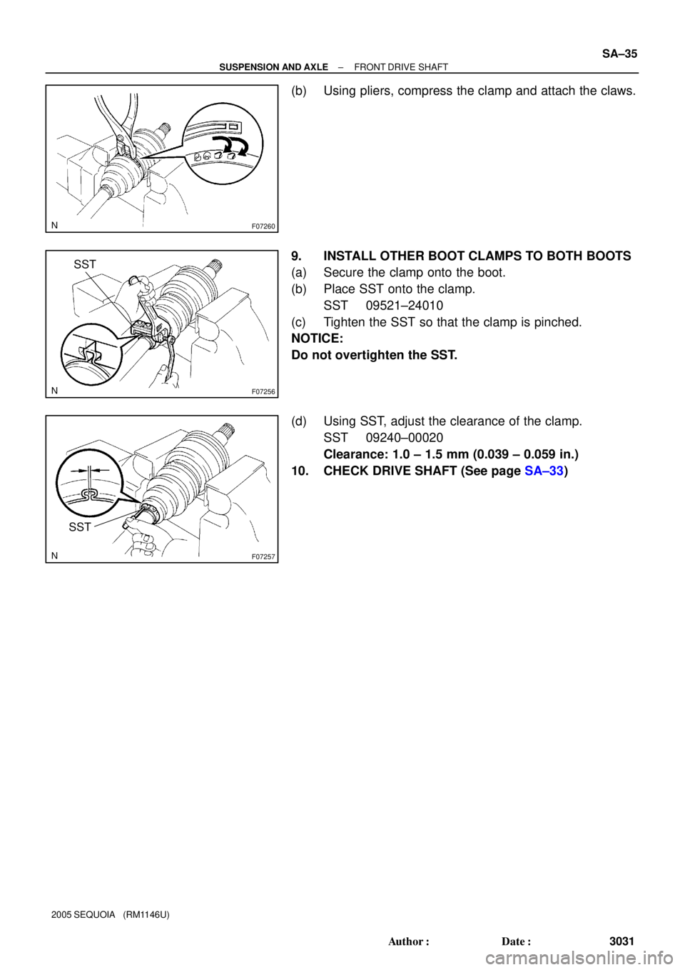
(b) Using pliers, compress the clamp and attach the claws.
9. INSTALL OTHER BOOT CLAMPS TO BOTH BOOTS
(a) Secure the clamp onto the boot.
(b) Place SST onto the clamp.
SST 09521±24010
(c) Tighten the SST so that the clamp is pinched.
NOTICE:
Do not overtighten the SST.
(d) Using SST, adjust the clearance of the clamp.
SST 09240±00020
Clearance: 1.0 ± 1.5 mm (0.039 ± 0.059 in.)
10. CHECK DRIVE SHAFT (See page SA±33)
Page 3046 of 4323
SA24Q±02
F06630
SA±42
± SUSPENSION AND AXLEFRONT DIFFERENTIAL CARRIER
3038 Author�: Date�:
2005 SEQUOIA (RM1146U)
REMOVAL
1. DRAIN DIFFERENTIAL OIL
2. REMOVE DRIVE SHAFTS (See page SA±31)
3. DISCONNECT FRONT PROPELLER SHAFT
(See page PR±7)
HINT:
Support the front propeller shaft securely.
4. REMOVE TUBE WITH WIRE HARNESS ASSEMBLY
(a) Disconnect the breather hose, vacuum hose and actuator
connector.
(b) Remove the bolt and tube with wire harness assembly.
5. REMOVE FRONT DIFFERENTIAL CARRIER
(a) Support the front differential with a jack.
(b) Using a hexagon (12 mm) wrench, remove the rear
mounting nut.
(c) Remove the 2 front mounting bolts.
(d) Lower the jack and remove the front differential carrier.
6. REMOVE DIFFERENTIAL MOUNTING CUSHIONS
(a) Remove the 2 bolts and rear mounting cushion.
(b) Remove the 5 bolts and 2 front mounting cushions.