Page 2462 of 4323
I28766
R6
Light Control
Rheostat AssyRadio and Navigation Assy
J/C
Steering Pad Switch Assy
Spiral Cable
Sub±assy From
TAILLIGHT
RelayILL±
SWG J/C
ILL+ W±G
GJ39 J40
J39 J40
J39 J40W±G
G
G
G A B
A
AAB
ILL±
T12
2
6 1
10C9±1
BR±W
C9±10 6
4
Steering SWR30
R27 R30 DI±2260
± DIAGNOSTICSNAVIGATION SYSTEM
2454 Author�: Date�:
2005 SEQUOIA (RM1146U)
Illumination circuit
CIRCUIT DESCRIPTION
Power is supplied to the radio and navigation panel illumination when the light control switch is in the TAIL
or HEAD position. The body ECU determines the external brightness based on the brightness level detected
by the automatic light control sensor, and then operates the TAILLIGHT relay. Power can also be supplied
by operating the relay.
The intensity of the radio receiver panel illumination can be adjusted by the rheostat switch.
WIRING DIAGRAM
DIDDF±01
Page 2493 of 4323
I28480
Combination Meter
SPD G±O 25
C53
R29 J17
J/C
BRadio and Navigation Assy
BG±O
± DIAGNOSTICSNAVIGATION SYSTEM
DI±2291
2485 Author�: Date�:
2005 SEQUOIA (RM1146U)
Speed signal circuit
CIRCUIT DESCRIPTION
The navigation ECU (built in the radio and navigation assy) receives a vehicle speed signal from the com-
bination meter assy and information about the GPS antenna, and then adjusts vehicle position.
HINT:
�A voltage of 12 V or 5 V is output from each ECU and then input to the combination meter. The signal
is changed to a pulse signal at the transistor in the combination meter. Each ECU controls the respec-
tive system based on the pulse signal.
�If a short occurs in an ECU, all systems in the speed signal circuit will not operate normally.
WIRING DIAGRAM
DIDDP±01
Page 2495 of 4323
I28748
Radio and Navigation Assy:
SPD
R29
I28569
Combination Meter Assy:
C5±25
± DIAGNOSTICSNAVIGATION SYSTEM
DI±2293
2487 Author�: Date�:
2005 SEQUOIA (RM1146U)
3 Check harness and connector (Combination meter assy ± Radio and navigation
assy).
PREPARATION:
Disconnect the radio and navigation assy and combination me-
ter assy connectors.
CHECK:
Measure the resistance according to the value(s) in the table
below.
OK:
Tester connectionConditionSpecified condition
SPD (R29±3) ± C5±25Ignition switch OFFBelow 1 W
SPD (R29±3) ±
Body groundIgnition switch OFF10 kW or higher
HINT:
If the resistance between terminal SPD and body ground is less
than 10 kW, there may be a short in a wire harness, connector,
or ECU.
NG Repair or replace harness or connector.
OK
Replace combination meter assy.
Page 2501 of 4323
DIDKN±01
I28851
R/B No. 2
� Heater Main Relay
(Marking: HTR)
Compressor
Condenser
Receiver Pressure Switch
Integration Panel Assembly
� A/C ECU
� A/C Switch
� Air Inlet Selector
Heater Unit
� Heater Radiator
� Air Mix Servomotor
� Air Outlet Servomotor
Cooling Unit
� Blower Motor Linear
Controller
� Evaporator
� Expansion Valve
� ThermistorBlower Unit
� Blower Motor
� Air Inlet Servomotor
Water Valve
Rear Heater
Control Assembly
Condenser Fan
Ambient
Temperature
Sensor
Solar Sensor
Room
Temperature
Sensor
Rear Room Temperature
± DIAGNOSTICSAIR CONDITIONING SYSTEM
DI±2299
2493 Author�: Date�:
2005 SEQUOIA (RM1146U)
LOCATION
Page 2509 of 4323

DIDKP±01
I15876
I21 I20I19
I22
± DIAGNOSTICSAIR CONDITIONING SYSTEM
DI±2307
2501 Author�: Date�:
2005 SEQUOIA (RM1146U)
TERMINALS OF ECU
Integration Control and Panel
Symbols (Terminals No.)Wiring ColorTerminal DescriptionConditionSpecified Condition
+B eGND
(I19±1 e I19±10)R e OPower source (Back±up)Always10 to 14 V
IG+ e GND
(I19±2 e I19±10)R±L e OPower source (IG)IG switch OFF " ON10 to 14 V
PSW e GNDLBOPithil
A/C refrigerant pressure: less than
0.19 MPa
(2.0 kgf/cm2)10 t 14B l 10VPSW e GND
(I19±6 e I19±10)L±B e OPressure switch signal0.19 MPa (2.0 kgf/cm)
or more than 3.14 MPa (32
Kgf/cm2)
10 to 14 " Below 1.0 V
HR e GND
(I22±6 e I19±10)L±Y e OBlower motor operation
signalBlower fan OFF "ON10 to 14 " Below 1.0 V
GND e Body ground
(I19±10 e Body ground)*1O e Body groundGround for main power
supplyConstantContinuity
ACC e GND
(I19±11 e I19±10)P e OPower source (ACC)Turn ignition switch ACC10 to 14 V
TA MSG TAMAbi tt tIG ON, Ambient temp.: 25°C (77°F)1.3 to 1.8 VTAM e SG±TAM
(I19±8 e I19±20)LG±B e Y±BAmbient temperature sen-
sor signalIG ON, Ambient temp.: 40°C
(104°F)0.8 to 1.3 V
BLW e GNDGBOBlower motor operationBl f OFFON10 t 14B l 10VBLW e GND
(I19±4 e I19±10)G±B e OBlower motor o eration
signalBlower fan OFF " ON10 to 14 " Below 1.0 V
RrCLK (I21±15)*1BCommunication signal
Communication circuit
(Built in Fr A/C control panel " Rr
A/C control panel)
±
RrDPD (I21±5)*1RCommunication signal
Communication circuit
(Built in Fr A/C control panel " Rr
A/C control panel)
±
RrSWD (I21±6)*1WCommunication signal
Communication circuit
(Built in Fr A/C control panel " Rr
A/C control panel)
±
RrAMH e GND
(I21±8 e I19±10)*1R±G e ORear air mix control ser-
vomotor operation signalRr temp. control switch: Max.
COOL " Max. HOTBelow 1.0 "
10 to 14 V for 16 sec.
RrAMC e GND
(I21±9 e I19±10)*1L±B e ORear air mix control ser-
vomotor operation signalRr temp. control switch: Max. HOT
" Max. COOLBelow 1.0 "
10 to 14 V for 16 sec.
RrSG e GND
(I21±10 e I19±10)*1L±R e OGround for rear evapora-
tor temperature sensorConstantContinuity
RrS5 e RrSG
(I22±4 e I21±10)*1L±Y e L±RPower supply for rear air
mix control servomotorIG ON4.5 to 5.5 V
Page 2603 of 4323

EM1WX±01
A08934
A04329
A04331
EM±16
± ENGINE MECHANICALTIMING BELT
2595 Author�: Date�:
2005 SEQUOIA (RM1146U)
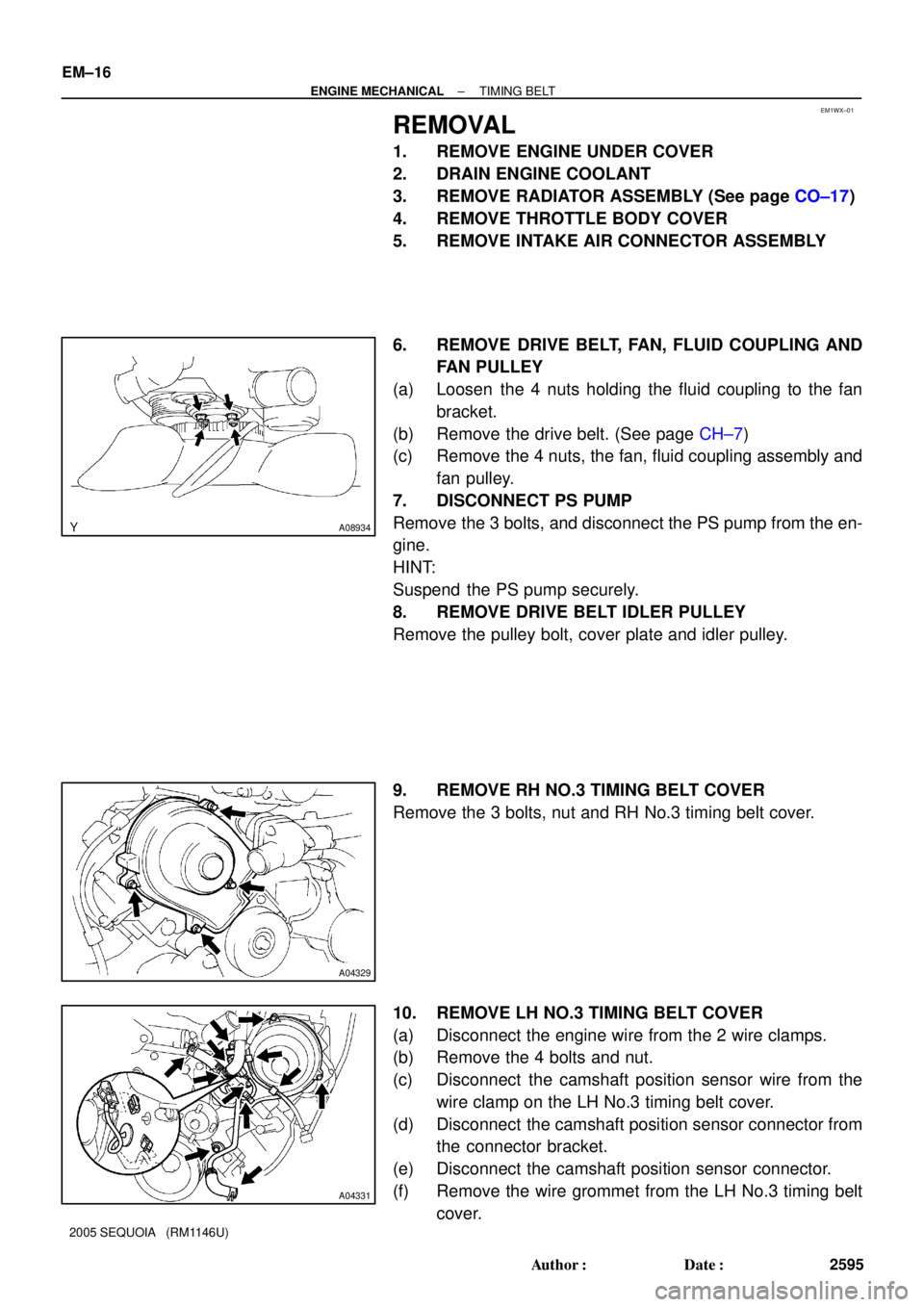
REMOVAL
1. REMOVE ENGINE UNDER COVER
2. DRAIN ENGINE COOLANT
3. REMOVE RADIATOR ASSEMBLY (See page CO±17)
4. REMOVE THROTTLE BODY COVER
5. REMOVE INTAKE AIR CONNECTOR ASSEMBLY
6. REMOVE DRIVE BELT, FAN, FLUID COUPLING AND
FAN PULLEY
(a) Loosen the 4 nuts holding the fluid coupling to the fan
bracket.
(b) Remove the drive belt. (See page CH±7)
(c) Remove the 4 nuts, the fan, fluid coupling assembly and
fan pulley.
7. DISCONNECT PS PUMP
Remove the 3 bolts, and disconnect the PS pump from the en-
gine.
HINT:
Suspend the PS pump securely.
8. REMOVE DRIVE BELT IDLER PULLEY
Remove the pulley bolt, cover plate and idler pulley.
9. REMOVE RH NO.3 TIMING BELT COVER
Remove the 3 bolts, nut and RH No.3 timing belt cover.
10. REMOVE LH NO.3 TIMING BELT COVER
(a) Disconnect the engine wire from the 2 wire clamps.
(b) Remove the 4 bolts and nut.
(c) Disconnect the camshaft position sensor wire from the
wire clamp on the LH No.3 timing belt cover.
(d) Disconnect the camshaft position sensor connector from
the connector bracket.
(e) Disconnect the camshaft position sensor connector.
(f) Remove the wire grommet from the LH No.3 timing belt
cover.
Page 2627 of 4323

A04456
No.2 Idler
Pulley Bolt
Timing
Mark
Crankshaft
Pulley Bolt
A23334
Movement
(25°)
SSTOil Control Valve
Installation Hole
A23335Service Bolt
A23336
EM±40
± ENGINE MECHANICALCYLINDER HEAD
2619 Author�: Date�:
2005 SEQUOIA (RM1146U)
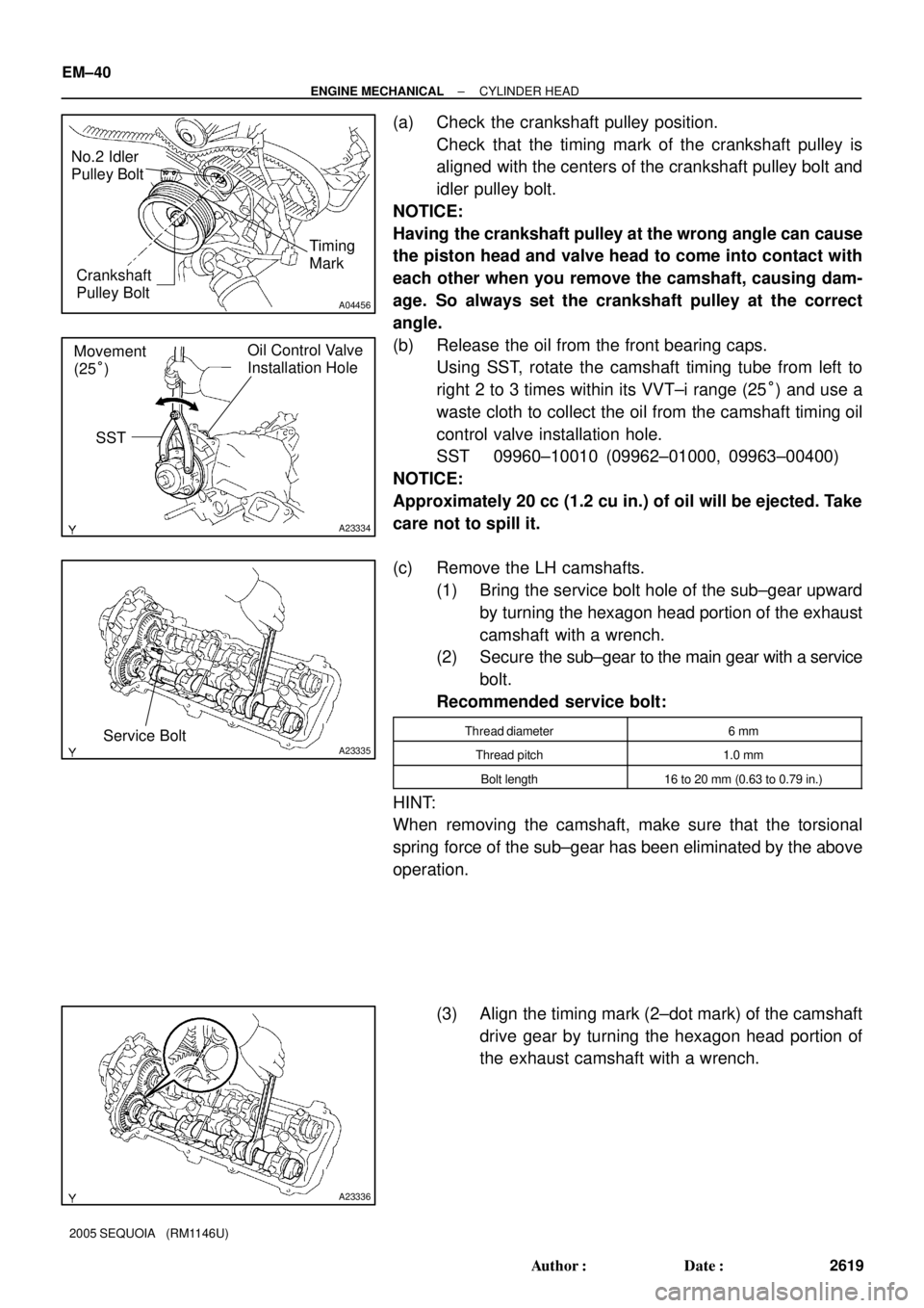
(a) Check the crankshaft pulley position.
Check that the timing mark of the crankshaft pulley is
aligned with the centers of the crankshaft pulley bolt and
idler pulley bolt.
NOTICE:
Having the crankshaft pulley at the wrong angle can cause
the piston head and valve head to come into contact with
each other when you remove the camshaft, causing dam-
age. So always set the crankshaft pulley at the correct
angle.
(b) Release the oil from the front bearing caps.
Using SST, rotate the camshaft timing tube from left to
right 2 to 3 times within its VVT±i range (25°) and use a
waste cloth to collect the oil from the camshaft timing oil
control valve installation hole.
SST 09960±10010 (09962±01000, 09963±00400)
NOTICE:
Approximately 20 cc (1.2 cu in.) of oil will be ejected. Take
care not to spill it.
(c) Remove the LH camshafts.
(1) Bring the service bolt hole of the sub±gear upward
by turning the hexagon head portion of the exhaust
camshaft with a wrench.
(2) Secure the sub±gear to the main gear with a service
bolt.
Recommended service bolt:
Thread diameter6 mm
Thread pitch1.0 mm
Bolt length16 to 20 mm (0.63 to 0.79 in.)
HINT:
When removing the camshaft, make sure that the torsional
spring force of the sub±gear has been eliminated by the above
operation.
(3) Align the timing mark (2±dot mark) of the camshaft
drive gear by turning the hexagon head portion of
the exhaust camshaft with a wrench.
Page 2628 of 4323

A23337
12
345
6
7
811
12 13
14
15
1617
18 2122
910 1920
A23338
Service Bolt
A23339
Approx.
10°
A23340
1 2
21
22
19 20
7
8 11
12
13
14
15
16
3
4 17
18
5
6 9
10
± ENGINE MECHANICALCYLINDER HEAD
EM±41
2620 Author�: Date�:
2005 SEQUOIA (RM1146U)
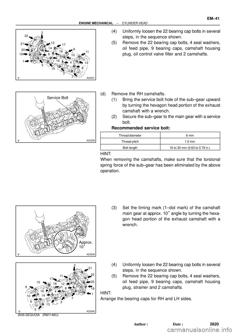
(4) Uniformly loosen the 22 bearing cap bolts in several
steps, in the sequence shown.
(5) Remove the 22 bearing cap bolts, 4 seal washers,
oil feed pipe, 9 bearing caps, camshaft housing
plug, oil control valve filter and 2 camshafts.
(d) Remove the RH camshafts.
(1) Bring the service bolt hole of the sub±gear upward
by turning the hexagon head portion of the exhaust
camshaft with a wrench.
(2) Secure the sub±gear to the main gear with a service
bolt.
Recommended service bolt:
Thread diameter6 mm
Thread pitch1.0 mm
Bolt length16 to 20 mm (0.63 to 0.79 in.)
HINT:
When removing the camshafts, make sure that the torsional
spring force of the sub±gear has been eliminated by the above
operation.
(3) Set the timing mark (1±dot mark) of the camshaft
main gear at approx. 10° angle by turning the hexa-
gon head portion of the exhaust camshaft with a
wrench.
(4) Uniformly loosen the 22 bearing cap bolts in several
steps, in the sequence shown.
(5) Remove the 22 bearing cap bolts, 4 seal washers,
oil feed pipe, 9 bearing caps, camshaft housing
plug, strainer and 2 camshafts.
HINT:
Arrange the bearing caps for RH and LH sides.