Page 2908 of 4323

CH0LZ±02
B16358
B16369SST (B)
SST (A)
Turn
B16371
SST (C)
SST (B)
Insert
B16372
SST (C)
SST (A)
Turn
B16370
Turn
SST (A)
SST (B)
CH±8
± CHARGINGGENERATOR
2900 Author�: Date�:
2005 SEQUOIA (RM1146U)
DISASSEMBLY
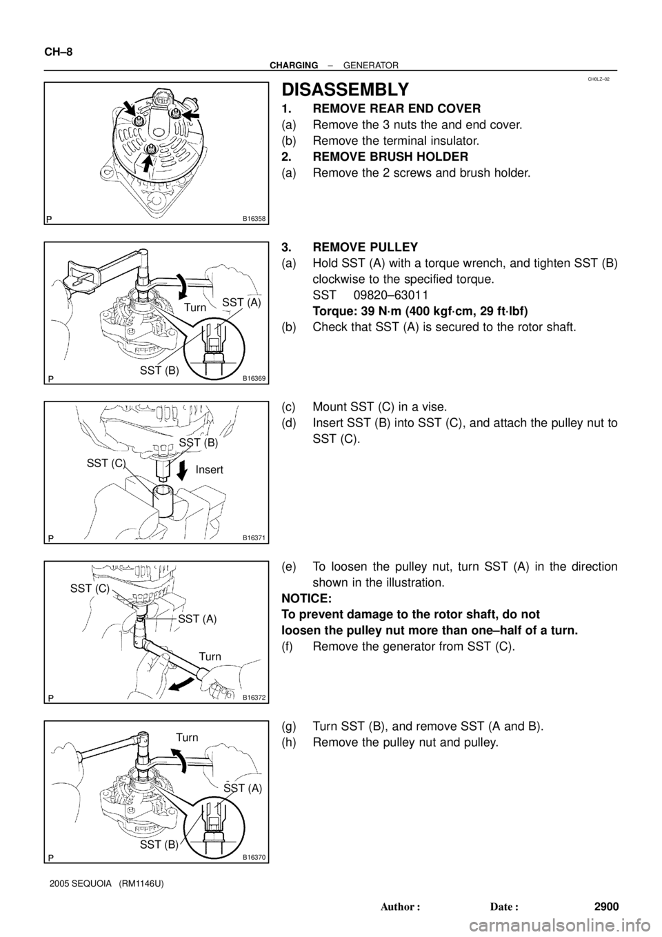
1. REMOVE REAR END COVER
(a) Remove the 3 nuts the and end cover.
(b) Remove the terminal insulator.
2. REMOVE BRUSH HOLDER
(a) Remove the 2 screws and brush holder.
3. REMOVE PULLEY
(a) Hold SST (A) with a torque wrench, and tighten SST (B)
clockwise to the specified torque.
SST 09820±63011
Torque: 39 N´m (400 kgf´cm, 29 ft´lbf)
(b) Check that SST (A) is secured to the rotor shaft.
(c) Mount SST (C) in a vise.
(d) Insert SST (B) into SST (C), and attach the pulley nut to
SST (C).
(e) To loosen the pulley nut, turn SST (A) in the direction
shown in the illustration.
NOTICE:
To prevent damage to the rotor shaft, do not
loosen the pulley nut more than one±half of a turn.
(f) Remove the generator from SST (C).
(g) Turn SST (B), and remove SST (A and B).
(h) Remove the pulley nut and pulley.
Page 2913 of 4323
CH0M2±02
B16368
Pulley
B16367
B12276
SST
B16364
B16369
TurnSST (A)
SST (B)
± CHARGINGGENERATOR
CH±13
2905 Author�: Date�:
2005 SEQUOIA (RM1146U)
REASSEMBLY
1. INSTALL ROTOR TO DRIVE END FRAME
(a) Place the drive end frame on the pulley.
(b) Install the rotor to the drive end frame.
2. INSTALL COIL ASSEMBLY
(a) Place the generator washer on the rotor.
(b) Using SST and a press, slowly press in the coil assembly.
SST 09285±76010
(c) Install the coil assembly with the 4 bolts.
Torque: 5.8 N´m (59 kgf´cm, 51 in.´lbf)
3. INSTALL PULLEY
(a) Install the pulley to the rotor shaft by tightening the pulley
nut by hand.
(b) Hold SST (A) with a torque wrench, and tighten SST (B)
clockwise to the specified torque.
SST 09820±63011
Torque: 39 N´m (400 kgf´cm, 29 ft´lbf)
(c) Check that SST (A) is secured to the pulley shaft.
Page 2943 of 4323

D05186
D13880
SST
F07266
D14215
A750E:
A750F:
± AUTOMATIC TRANSMISSION (A750E, A750F)AUTOMATIC TRANSMISSION UNIT
AT±27
2935 Author�: Date�:
2005 SEQUOIA (RM1146U)
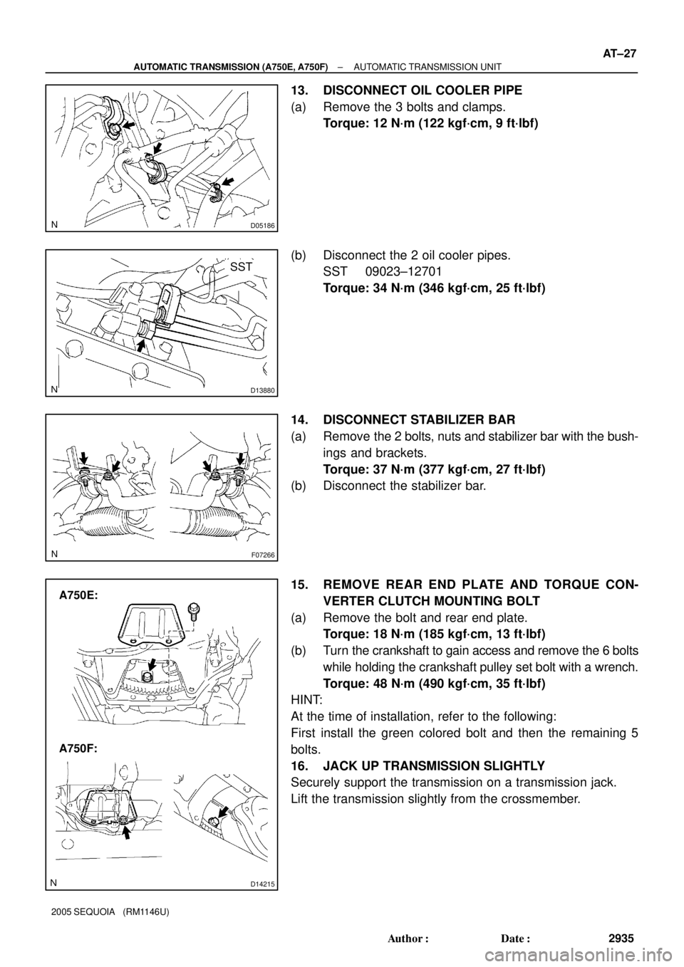
13. DISCONNECT OIL COOLER PIPE
(a) Remove the 3 bolts and clamps.
Torque: 12 N´m (122 kgf´cm, 9 ft´lbf)
(b) Disconnect the 2 oil cooler pipes.
SST 09023±12701
Torque: 34 N´m (346 kgf´cm, 25 ft´lbf)
14. DISCONNECT STABILIZER BAR
(a) Remove the 2 bolts, nuts and stabilizer bar with the bush-
ings and brackets.
Torque: 37 N´m (377 kgf´cm, 27 ft´lbf)
(b) Disconnect the stabilizer bar.
15. REMOVE REAR END PLATE AND TORQUE CON-
VERTER CLUTCH MOUNTING BOLT
(a) Remove the bolt and rear end plate.
Torque: 18 N´m (185 kgf´cm, 13 ft´lbf)
(b) Turn the crankshaft to gain access and remove the 6 bolts
while holding the crankshaft pulley set bolt with a wrench.
Torque: 48 N´m (490 kgf´cm, 35 ft´lbf)
HINT:
At the time of installation, refer to the following:
First install the green colored bolt and then the remaining 5
bolts.
16. JACK UP TRANSMISSION SLIGHTLY
Securely support the transmission on a transmission jack.
Lift the transmission slightly from the crossmember.
Page 2948 of 4323

TR04H±04
TR±2
± TRANSFERTROUBLESHOOTING
2940 Author�: Date�:
2005 SEQUOIA (RM1146U)
TROUBLESHOOTING
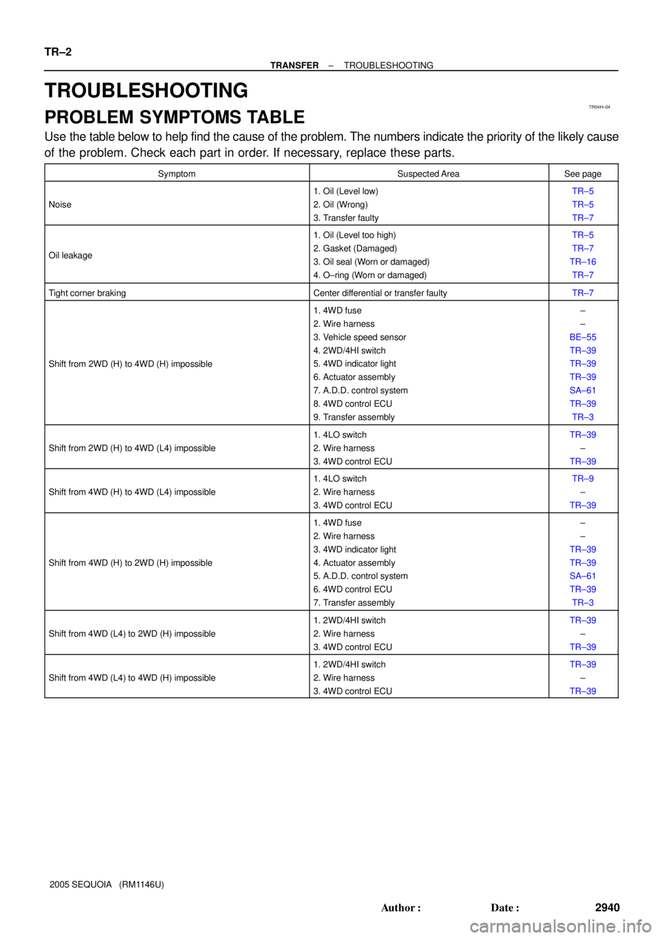
PROBLEM SYMPTOMS TABLE
Use the table below to help find the cause of the problem. The numbers indicate the priority of the likely cause
of the problem. Check each part in order. If necessary, replace these parts.
SymptomSuspected AreaSee page
Noise
1. Oil (Level low)
2. Oil (Wrong)
3. Transfer faultyTR±5
TR±5
TR±7
Oil leakage
1. Oil (Level too high)
2. Gasket (Damaged)
3. Oil seal (Worn or damaged)
4. O±ring (Worn or damaged)TR±5
TR±7
TR±16
TR±7
Tight corner brakingCenter differential or transfer faultyTR±7
Shift from 2WD (H) to 4WD (H) impossible
1. 4WD fuse
2. Wire harness
3. Vehicle speed sensor
4. 2WD/4HI switch
5. 4WD indicator light
6. Actuator assembly
7. A.D.D. control system
8. 4WD control ECU
9. Transfer assembly±
±
BE±55
TR±39
TR±39
TR±39
SA±61
TR±39
TR±3
Shift from 2WD (H) to 4WD (L4) impossible
1. 4LO switch
2. Wire harness
3. 4WD control ECUTR±39
±
TR±39
Shift from 4WD (H) to 4WD (L4) impossible
1. 4LO switch
2. Wire harness
3. 4WD control ECUTR±9
±
TR±39
Shift from 4WD (H) to 2WD (H) impossible
1. 4WD fuse
2. Wire harness
3. 4WD indicator light
4. Actuator assembly
5. A.D.D. control system
6. 4WD control ECU
7. Transfer assembly±
±
TR±39
TR±39
SA±61
TR±39
TR±3
Shift from 4WD (L4) to 2WD (H) impossible
1. 2WD/4HI switch
2. Wire harness
3. 4WD control ECUTR±39
±
TR±39
Shift from 4WD (L4) to 4WD (H) impossible
1. 2WD/4HI switch
2. Wire harness
3. 4WD control ECUTR±39
±
TR±39
Page 2980 of 4323
TR0DK±01
F19268
F19269
F19270
F19298
TR±34
± TRANSFERINPUT SHAFT
2972 Author�: Date�:
2005 SEQUOIA (RM1146U)
INSPECTION
1. REMOVE 2 OIL SEAL RINGS
2. INSPECT INPUT SHAFT
(a) Using a micrometer, measure the outer diameter of the in-
put shaft journal surface.
Minimum diameter: 47.59 mm (1.8736 in.)
If the outer diameter is less than the minimum, replace the input
shaft.
(b) Using a dial indicator, measure the inside diameter of the
input shaft bushing.
Maximum diameter: 48.14 mm (1.8953 in.)
If the inside diameter exceeds the maximum, replace the input
shaft.
3. INSTALL 2 OIL SEAL RINGS
HINT:
�Apply gear oil to the oil seal ring.
�Engage securely to eliminate clearance as shown in the
illustration.
Page 2983 of 4323

F19297
F19275
SST
F19296
SST
F19274
± TRANSFERPLANETARY GEAR
TR±37
2975 Author�: Date�:
2005 SEQUOIA (RM1146U)
(d) Select a snap ring that allows for the minimum axial play.
MarkThickness mm (in.)
11.45 to 1.50 (0.0571 to 0.0591)
21.50 to 1.55 (0.0591 to 0.0610)
31.55 to 1.60 (0.0610 to 0.0630)
41.60 to 1.65 (0.0630 to 0.0650)
51.65 to 1.70 (0.0650 to 0.0669)
(e) Using a snap ring expander, install a new snap ring.
4. IF NECESSARY, REPLACE LOW PLANETARY GEAR
BEARING
(a) Using SST, remove the low planetary gear bearing.
NOTICE:
Engage the claws of the SST securely so that there is no
clearance between the bearing and low planetary gear.
SST 09612±65014 (09612±01030, 09612±01050)
(b) Using SST and a press, drive in a new bearing.
SST 09950±60010 (09951±00570), 09950±70010
(09951±07100)
Bearing press in depth:
7.7 to 8.3 mm (0.303 to 0.327 in.)
5. REMOVE LOW PLANETARY GEAR SPLINE PIECE
(a) Using a screwdriver, remove the snap ring.
(b) Remove the low planetary gear spline piece to the low
planetary gear.
6. INSTALL LOW PLANETARY GEAR SPLINE PIECE
(a) Install the low planetary gear spline piece to the low plan-
etary gear.
(b) Using a screwdriver, install the snap ring.
Page 2984 of 4323
TR0CL±02
F19803
Differential Lock Switch
Transfer Actuator Four Wheel Drive Control ECU
2WD/4HI Switch4LO Switch
TR±38
± TRANSFERONE TOUCH 2±4 SELECTOR SYSTEM
2976 Author�: Date�:
2005 SEQUOIA (RM1146U)
ONE TOUCH 2±4 SELECTOR SYSTEM
LOCATION
Page 2989 of 4323

F19340
A
B Four Wheel Drive Control ECU:
Transfer Actuator:
± TRANSFERONE TOUCH 2±4 SELECTOR SYSTEM
TR±43
2981 Author�: Date�:
2005 SEQUOIA (RM1146U)
10. INSPECT ACTUATOR
NOTICE:
Inspect the actuator with the transfer removed from the vehicle.
(a) Turn the ignition switch to ON.
(b) Check the operating sound produced by four wheel drive control switch operation and the differential
lock switch operation.
If the operating sound cannot be heard, check the four wheel control ECU and the wire harness in the next
step. When the wire harness and four wheel drive control ECU are normal, replace the actuator.
11. INSPECT WIRE HARNESS
(a) Disconnect the actuator connector and four wheel drive
control ECU connector.
(b) Check continuity of the wire harness between the four
wheel drive control ECU and the actuator.
Tester connectionSpecified condition
TM1 (A±2) ± TM1 (B±2)Continuity
TM2 (A±1) ± TM2 (B±1)Continuity
TL1 (A±41) ± TL1 (B±3)Continuity
TL2 (A±40) ± TL2 (B±4)Continuity
TL3 (A±39) ± TL3 (B±5)Continuity
HM2 (A±4) ± HM2 (B±7)Continuity
HM1 (A±3) ± HM1 (B±8)Continuity
P1 (A±10) ± CDL (B±9)Continuity
HL2 (A±42) ± HL2 (B±11)Continuity
HL1 (A±23) ± HL1 (B±12)Continuity
GND (A±7) ± GND (B±6)Continuity
GND (A±7) ± GND (B±10)Continuity
If continuity is not as specified, repair or replace the wire har-
ness.