Page 3218 of 4323

DISASSEMBLY
1. REMOVE REAR WHEEL
Torque: 110 N´m (1,122 kgf´cm, 81 ft´lbf)
2. REMOVE REAR D")
BR1NF±02
F13327
F13323
F13324
± BRAKEPARKING BRAKE
BR±43
3210 Author�: Date�:
2005 SEQUOIA (RM1146U)
DISASSEMBLY
1. REMOVE REAR WHEEL
Torque: 110 N´m (1,122 kgf´cm, 81 ft´lbf)
2. REMOVE REAR DISC BRAKE ASSEMBLY
(a) Remove the 2 mounting bolts and remove the disc brake
assembly.
Torque: 105 N´m (1,070 kgf´cm, 77 ft´lbf)
(b) Suspend the disc brake securely and so the hose is not
stretched.
3. REMOVE DISC
(a) Release the parking brake lever.
(b) Place matchmarks on the disc and rear axle hub.
(c) Remove the disc.
HINT:
�If the disc cannot be removed easily, turn the shoe adjust-
er until the wheel turns freely.
�If there are no matchmarks, temporarily install the disc,
then measure the disc runout and install the disc in posi-
tion (See page BR±39).
4. REMOVE SHOE RETURN SPRINGS
Using needle±nose pliers, remove the 2 shoe return springs.
5. REMOVE SHOE STRUT WITH SPRING
HINT:
At the time of reassembly, install the strut with the spring facing
forward.
6. REMOVE SHOE ADJUSTER
Slide the front shoe toward outside, remove the shoe adjuster.
7. REMOVE FRONT SHOE
(a) Using a needle±nose pliers, disconnect the anchor spring
and tension spring from the front shoe.
(b) Remove the anchor spring and tension spring.
Page 3225 of 4323
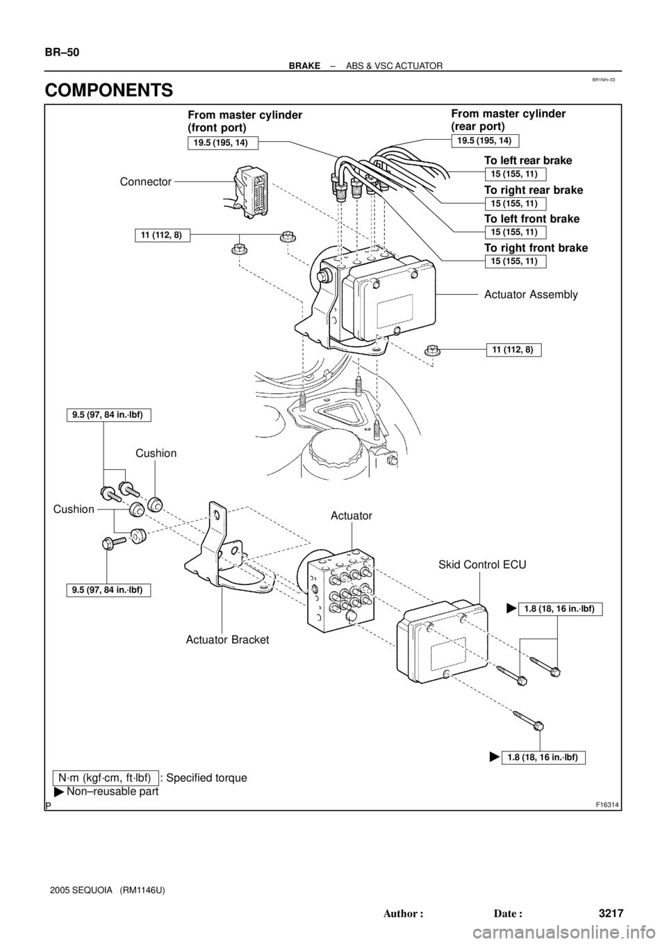
BR1NH±03
F16314
Connector
11 (112, 8)
Actuator BracketActuator CushionActuator Assembly
11 (112, 8)
1.8 (18, 16 in.´lbf)
: Specified torqueN´m (kgf´cm, ft´lbf)
19.5 (195, 14)
15 (155, 11)
� Non±reusable part�
19.5 (195, 14)
15 (155, 11)
15 (155, 11)
9.5 (97, 84 in.´lbf)
9.5 (97, 84 in.´lbf)
Skid Control ECU
�
Cushion
To left rear brake
To right front brake To right rear brake
To left front brake From master cylinder
(front port)From master cylinder
(rear port)
15 (155, 11)
1.8 (18, 16 in.´lbf)
BR±50
± BRAKEABS & VSC ACTUATOR
3217 Author�: Date�:
2005 SEQUOIA (RM1146U)
COMPONENTS
Page 3227 of 4323
BR1NJ±03
F13898
Sealing
Surface
BR±52
± BRAKEABS & VSC ACTUATOR
3219 Author�: Date�:
2005 SEQUOIA (RM1146U)
DISASSEMBLY
1. REMOVE ACTUATOR BRACKET
(a) Remove the 3 bolts and actuator bracket.
Torque: 9.5 N´m (97 kgf´cm, 84 in.´lbf)
(b) Remove the 3 cushions from the actuator bracket.
2. REMOVE SKID CONTROL ECU
Using a E5 torx® wrench, remove the 3 screws and skid control
ECU.
Torque: 1.8 N´m (18 kgf´cm, 16 in.´lbf)
NOTICE:
Protect the actuator in order to prevent sealing surface
from getting dirty and causing damage on the valve body.
If the dirt and the like is stuck to the sealing surface, use
plastic tools or soft objects to remove the dirt. Do not use
chemical solvents.
Page 3229 of 4323
BR1NL±04
BR±54
± BRAKEABS & VSC ACTUATOR
3221 Author�: Date�:
2005 SEQUOIA (RM1146U)
INSTALLATION
Installation is in the reverse order of removal (See page BR±51).
HINT:
�After installation, fill the brake reservoir with brake fluid and bleed brake system (See page BR±4).
�Check for leaks.
NOTICE:
In case of replacing the skid control ECU, perform the zero point calibration of the steering angle,
master cylinder pressure, yawrate and deceleration sensors (See page DI±897).
Page 3276 of 4323

DISASSEMBLY
NOTICE:
When using a vise, do not o")
SR0V9±05
F13620
SST
F06746
SSTBolt SST
Nut
F06747
Matchmarks
F06748
± STEERINGPOWER STEERING GEAR
SR±41
3268 Author�: Date�:
2005 SEQUOIA (RM1146U)
DISASSEMBLY
NOTICE:
When using a vise, do not overtighten it.
1. REMOVE 2 TURN PRESSURE TUBES
(a) Using SST, remove the 2 turn pressure tubes.
SST 09023±38401
(b) Remove the 4 O±rings from the tubes.
2. SECURE PS GEAR ASSEMBLY IN VISE
Using SST, 2 bolts and nuts, secure the gear assembly in a vise,
as shown in the illustration.
SST 09612±00012
Reference:
Bolt: 90105±10346
Nut: 90170±10198
HINT:
Use 2 of the same type of SST.
3. REMOVE RH AND LH TIE ROD ENDS AND LOCK
NUTS
(a) Put matchmarks on the tie rod end, lock nut and rack end.
(b) Loosen the lock nut, remove the tie rod end and lock nut.
(c) Perform the same procedure on the other side.
4. REMOVE RH AND LH CLIPS, RACK BOOTS AND
CLAMPS
(a) Using a screwdriver, loosen the 2 clamps.
(b) Remove the 2 clips and boots.
HINT:
Mark the RH and LH boots.
NOTICE:
Be careful not to damage the boot.
Page 3292 of 4323

SRS AIRBAG
PRECAUTION
CAUTION:
�The vehicle is equipped with SRS, which consists of a driver ai")
RS0B6±09
± SUPPLEMENTAL RESTRAINT SYSTEMSRS AIRBAG
RS±1
3284 Author�: Date�:
2005 SEQUOIA (RM1146U)
SRS AIRBAG
PRECAUTION
CAUTION:
�The vehicle is equipped with SRS, which consists of a driver airbag, front passenger airbag,
side airbag and curtain shield airbag. Failure to carry out service operations in the correct se-
quence could cause the SRS to unexpectedly deploy during servicing, possibly leading to a
serious accident. Further, if a mistake is made in servicing the SRS, it is possible that the SRS
may fail to operate when required. Before performing servicing (including removal or installa-
tion of parts, inspection or replacement), be sure to read the following items carefully, then fol-
low the correct procedures indicated in the repair manual.
�Wait at least 90 seconds after the ignition switch is turned to the ºLOCKº position and the nega-
tive (±) terminal cable is disconnected from the battery.
(The SRS is equipped with a back±up power source, so that if work is started within 90 seconds
after disconnecting the negative (±) terminal cable of the battery, the SRS may be deployed.)
�Do not expose the steering wheel pad, front passenger airbag assembly, side airbag assembly,
curtain shield airbag assembly, airbag sensor assembly, front airbag sensor, side airbag sen-
sor assembly, curtain shield airbag sensor assembly, seat position sensor assembly or occu-
pant classification ECU directly to hot air or flames.
�Be sure to perform the initialization of the occupant classification ECU if any of the following
conditions occur (see page DI±1128). If the initialization is not performed, the SRS may not oper-
ate properly.
�The occupant classification ECU is replaced.
�Accessories (seatback tray, seat cover, etc.) are installed to the vehicle.
�The passenger seat is removed from the vehicle, and then reinstalled or replaced.
�The passenger airbag ON/OFF indicator light (ºOFFº) comes on when the passenger seat
is not occupied.
�The vehicle is brought to the workshop for repair due to an accident or collision.
NOTICE:
�Malfunction symptoms of the SRS are difficult to confirm, so DTCs are the most important
source of information when troubleshooting. When troubleshooting the SRS, always inspect
DTCs before disconnecting the battery.
�Even in the case of a minor collision when the SRS does not deploy, the steering wheel pad,
front passenger airbag assembly, side airbag assembly, curtain shield airbag assembly, airbag
sensor assembly, front airbag sensor, side airbag sensor assembly, curtain shield airbag sen-
sor assembly, seat position sensor assembly and occupant classification ECU should be in-
spected. (see page RS±22, RS±35, RS±49, RS±64, RS±72, RS±83, RS±88, RS±93, RS±98,
RS±106 and RS±112).
�Before repair work, remove the airbag sensor if any kind of shock is likely to occur to the airbag
sensor during the operation.
�Never use SRS parts from another vehicle. When replacing the parts, replace them with new
ones.
�Never disassemble or repair the steering wheel pad, front passenger airbag assembly, side air-
bag assembly, curtain shield airbag assembly, airbag sensor assembly, front airbag sensor,
side airbag sensor assembly, curtain shield airbag sensor assembly, seat position sensor as-
sembly or occupant classification ECU in order to reuse it.
Page 3293 of 4323

�If the steering wheel pad, front passenger airbag assembly, side airbag assembly, curtain
shield airbag")
RS±2
± SUPPLEMENTAL RESTRAINT SYSTEMSRS AIRBAG
3285 Author�: Date�:
2005 SEQUOIA (RM1146U)
�If the steering wheel pad, front passenger airbag assembly, side airbag assembly, curtain
shield airbag assembly, airbag sensor assembly, front airbag sensor, side airbag sensor as-
sembly, curtain shield airbag sensor assembly, seat position sensor assembly or occupant
classification ECU has been dropped, or if there are any cracks, dents or other defects in the
case, bracket or connector, replace it with a new one.
�Use a volt/ohmmeter with high impedance (10 kW/V minimum) for troubleshooting the electrical
circuits.
�Information labels are attached to the periphery of the SRS components. Follow the instruc-
tions in the caution.
�After work on the SRS is completed, perform the SRS warning light check (see page DI±1137).
�When the negative (±) terminal cable is disconnected from the battery, the memory will be
cleared. Because of this, be sure to make a record of the contents memorized in each system
before starting work. When work is finished, adjust each system as it was before. Never use
a back±up power supply from outside the vehicle to avoid erasing the memory in any system.
Page 3294 of 4323

OPERATION
CAUTION:
Be sure to perform the initialization of th")
RS116±01
H24695
H23918Spiral Cable
H16182
± SUPPLEMENTAL RESTRAINT SYSTEMSRS AIRBAG
RS±3
3286 Author�: Date�:
2005 SEQUOIA (RM1146U)
OPERATION
CAUTION:
Be sure to perform the initialization of the occupant classi-
fication ECU if any of the following conditions occur (see
page DI±1128). If the initialization is not performed, the SRS
may not operate properly.
�The occupant classification ECU is replaced.
�Accessories (seatback tray, seat cover, etc.) are
installed to the vehicle.
�The passenger seat is removed from the vehicle, and
then reinstalled or replaced.
�The passenger airbag ON/OFF indicator light (ºOFFº)
comes on when the passenger seat is not occupied.
�The vehicle is brought to the workshop for repair due
to an accident or collision.
1. STEERING WHEEL PAD
The inflator and bag of the SRS are stored in the steering wheel
pad and cannot be disassembled. The inflator contains a squib,
igniter charge, and gas generator, etc., and inflates the bag
when instructed by the airbag sensor assembly. The steering
wheel pad cannot be disassembled.
2. SPIRAL CABLE
A spiral cable is used as an electrical joint from the vehicle body
side to the steering wheel. The spiral cable cannot be disas-
sembled.
3. FRONT PASSENGER AIRBAG ASSEMBLY
The inflator and bag of the SRS are stored in the front passen-
ger airbag assembly and cannot be disassembled. The inflator
contains a squib, igniter charge, gas generator, etc., and in-
flates the bag when instructed by the airbag sensor assembly.
The front passenger airbag assembly cannot be disassembled.