Page 3308 of 4323
H24687
H24688
Housing Lock
(White Part) A
CPA (Yellow Part)
Connection is
completed
± SUPPLEMENTAL RESTRAINT SYSTEMSRS AIRBAG
RS±17
3300 Author�: Date�:
2005 SEQUOIA (RM1146U)
23. CONNECTION OF CONNECTOR FOR FRONT AIRBAG SENSOR
(a) Before connecting the connectors, check that the position of the housing lock (the white part) is as
shown in the illustration.
(b) Be sure to engage the connectors until they are locked. (When locking, make sure that a click sound
can be heard.)
HINT:
When connecting them, the housing lock (white part) slides. Be sure not to hold the housing lock (white part)
and A part, as it may result in an insecure fit.
Page 3309 of 4323
H01584
Slider
Disconnection is completed Slider
H01585
SliderSlider
RS±18
± SUPPLEMENTAL RESTRAINT SYSTEMSRS AIRBAG
3301 Author�: Date�:
2005 SEQUOIA (RM1146U)
24. DISCONNECTION OF CONNECTOR FOR SIDE AIRBAG ASSEMBLY
(a) Place a finger on the slider, slide the slider to release the lock, and then disconnect the connector.
25. CONNECTION OF CONNECTOR FOR SIDE AIRBAG ASSEMBLY
(a) Connect the connector as shown in the illustration. (When locking, make sure that the slider returns
to its original position and a click sound can be heard.)
HINT:
When connecting, the slider will slide. Be sure not to touch the slider while connecting, as it may result in
an insecure fit.
Page 3310 of 4323
H02763
Outer
H02764
Lock of connector is released
Disconnection is completed
H02768
Outer
Outer
Connection is completed
± SUPPLEMENTAL RESTRAINT SYSTEMSRS AIRBAG
RS±19
3302 Author�: Date�:
2005 SEQUOIA (RM1146U)
26. DISCONNECTION OF CONNECTORS FOR SIDE AIR-
BAG SENSOR AND CURTAIN SHIELD AIRBAG SEN-
SOR
(a) While holding both outer flank sides, slide the outer in the
direction shown by the arrow.
(b) When the connector lock is released, the connectors are
disconnected.
HINT:
Be sure to hold both outer flank sides. Holding the top and bot-
tom sides will make disconnection difficult.
27. CONNECTION OF CONNECTORS FOR SIDE AIRBAG SENSOR AND CURTAIN SHIELD AIRBAG
SENSOR
(a) Connect the connector as shown in the illustration. (When locking, make sure that the outer returns
to its original position and a click sound can be heard.)
HINT:
When connecting, the outer will slide. Be sure not to hold the outer while connecting, as it may result in an
insecure fit.
Page 3401 of 4323
RS0UU±05
H23937
Front Seat Assembly RH
Occupant Classification ECU
RS±110
± SUPPLEMENTAL RESTRAINT SYSTEMOCCUPANT CLASSIFICATION ECU
3393 Author�: Date�:
2005 SEQUOIA (RM1146U)
OCCUPANT CLASSIFICATION ECU
COMPONENTS
Page 3402 of 4323
RS0UV±06
H23938
± SUPPLEMENTAL RESTRAINT SYSTEMOCCUPANT CLASSIFICATION ECU
RS±111
3394 Author�: Date�:
2005 SEQUOIA (RM1146U)
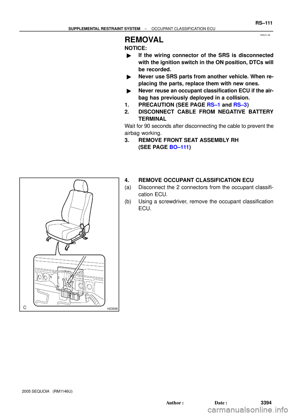
REMOVAL
NOTICE:
�If the wiring connector of the SRS is disconnected
with the ignition switch in the ON position, DTCs will
be recorded.
�Never use SRS parts from another vehicle. When re-
placing the parts, replace them with new ones.
�Never reuse an occupant classification ECU if the air-
bag has previously deployed in a collision.
1. PRECAUTION (SEE PAGE RS±1 and RS±3)
2. DISCONNECT CABLE FROM NEGATIVE BATTERY
TERMINAL
Wait for 90 seconds after disconnecting the cable to prevent the
airbag working.
3. REMOVE FRONT SEAT ASSEMBLY RH
(SEE PAGE BO±111)
4. REMOVE OCCUPANT CLASSIFICATION ECU
(a) Disconnect the 2 connectors from the occupant classifi-
cation ECU.
(b) Using a screwdriver, remove the occupant classification
ECU.
Page 3403 of 4323
RS0UW±06
RS±112
± SUPPLEMENTAL RESTRAINT SYSTEMOCCUPANT CLASSIFICATION ECU
3395 Author�: Date�:
2005 SEQUOIA (RM1146U)
INSPECTION
1. VEHICLE NOT INVOLVED IN COLLISION
Perform a diagnostic system check (see page DI±1147).
2. VEHICLE INVOLVED IN COLLISION
(a) Perform a diagnostic system check (see page DI±1147).
(b) Even if the airbag was not deployed, perform a visual check for damage to the occupant classification
ECU. If there are any defects mentioned below, replace the occupant classification ECU with a new
one:
�Cracks, dents or chips in the case.
�Cracks or other damage to the connector.
CAUTION:
For removal and installation procedures of the occupant classification ECU, see page RS±111 and
RS±114. Be sure to follow the correct procedure.
Page 3404 of 4323
RS0UX±05
± SUPPLEMENTAL RESTRAINT SYSTEMOCCUPANT CLASSIFICATION ECU
RS±113
3396 Author�: Date�:
2005 SEQUOIA (RM1146U)
REPLACEMENT
REPLACEMENT REQUIREMENTS
In the following cases, replace the occupant classification ECU with a new one.
�The occupant classification ECU has been found to be faulty in troubleshooting.
�The occupant classification ECU has been dropped.
CAUTION:
For removal and installation procedures of the occupant classification ECU, see page RS±111 and
RS±114. Be sure to follow the correct procedure.
Page 3405 of 4323

INSTALLATION
NOTICE:
�Never use SRS parts from another vehicle. When")
RS0UY±06
H23939
RS±114
± SUPPLEMENTAL RESTRAINT SYSTEMOCCUPANT CLASSIFICATION ECU
3397 Author�: Date�:
2005 SEQUOIA (RM1146U)
INSTALLATION
NOTICE:
�Never use SRS parts from another vehicle. When re-
placing parts, replace them with new ones.
�Never reuse the occupant classification ECU in-
volved in a collision when the airbag has deployed.
�If the occupant classification ECU center has been
dropped, or there are any cracks, dents or other de-
fects in the case, bracket or connector, replace it with
a new one.
�When installing the seat position sensor assembly
center, be careful that the SRS wiring does not inter-
fere with other parts and that it is not pinched be-
tween other parts.
1. INSTALL OCCUPANT CLASSIFICATION ECU
(a) Install the occupant classification ECU.
(b) Connect the 2 connectors to the occupant classification
ECU.
2. INSTALL FRONT SEAT ASSEMBLY RH
(SEE PAGE BO±123)
3. CONNECT CABLE TO NEGATIVE BATTERY TERMI-
NAL
4. PERFORM INITIALIZATION (SEE PAGE BE±77)
Some system need initialization when disconnecting the cable
from the negative battery terminal.
5. INITIALIZE OCCUPANT CLASSIFICATION ECU
(SEE PAGE DI±1137)
6. INSPECT SRS WARNING LIGHT (SEE PAGE DI±1137)